

Honeywell TH450 Owners Manual
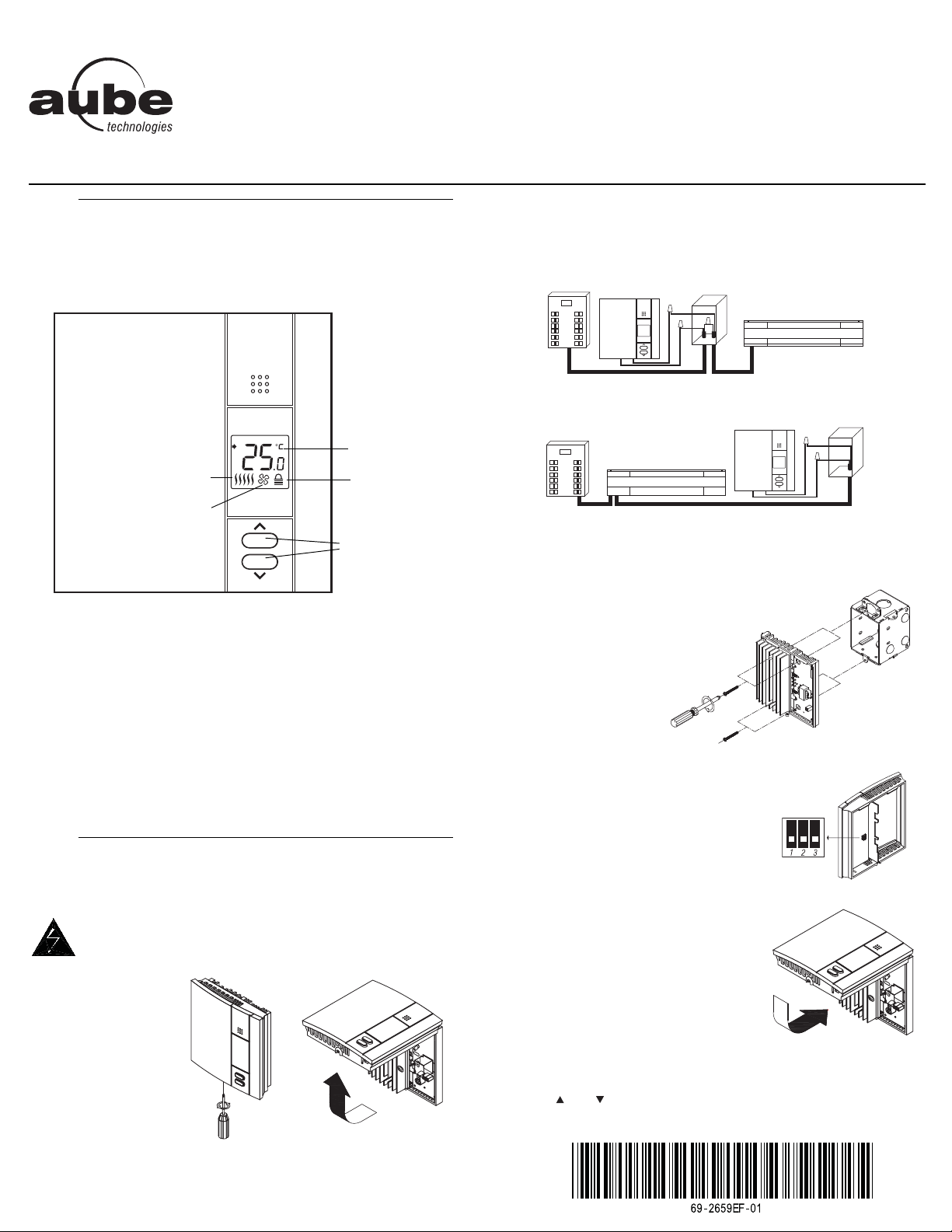
TH450
Temperature
display
Temperature
adjustment
buttons
Keypad lock
Heating intensity
Appears when the thermostat
is configured for a fan-forced
heater.
Electrical
panel
Heater
Electrical
box
Thermostat
Electrical
panel
Heater
Electrical
box
Thermostat
Install the wallplate to the electrical box.
Owner’s Guide
Non-programmable Thermostat
Description
The TH450 thermostat is designed to control an electric heating system such as a baseboard heater, a radiant ceiling, a convector or a
fan-forced convector.
This thermostat cannot be used with:
• a resistive load under 1.25 A
• a resistive load over 16.7 A
• a system driven by a contactor or a relay (inductive load)
• a central heating system
1.
Make the connections using solderless connectors for copper wires. The
thermostat wires are non-polarized; this means either wire can be connected to either terminal.
WARNING: This thermostat has tinned copper wires for line and load
connections. Special CO/ALR solderless connectors must be used when
connecting with aluminium conductors.
SUPPLIED PARTS
• One (1) thermostat
• Two (2) 6-32 mounting screws
• Two (2) solderless connectors
Installation
The installation must be carried out by an electrician and must
comply with local electrical codes.
CUT POWER TO THE HEATING SYSTEM AT THE MAIN
ELECTRICAL PANEL TO AVOID ANY RISK OF ELECTRICAL SHOCK.
Loosen the screw and
remove the faceplate
of the thermostat from
its wallplate.
NOTE: The screw
remains captive on the
wallplate.
Set the configuration switches on the back
of the thermostat’s faceplate (see section 3).
2.
Install the faceplate of the thermostat back
on the wallplate and tighten the screw.
NOTE: If there is a protective film or sticker
on the thermostat’s screen, peel it off.
Apply power to the thermostat. Verify the installation by checking that the
heater can be turned On and Off by raising and lowering the setpoint
using the and buttons.
NOTE: Keep the air vents of thermostat clean and unobstructed at all
times.
TH450 1/2
The configuration switches are on the back of the thermostat. The
factory settings are indicated by the gray cells in the following table.
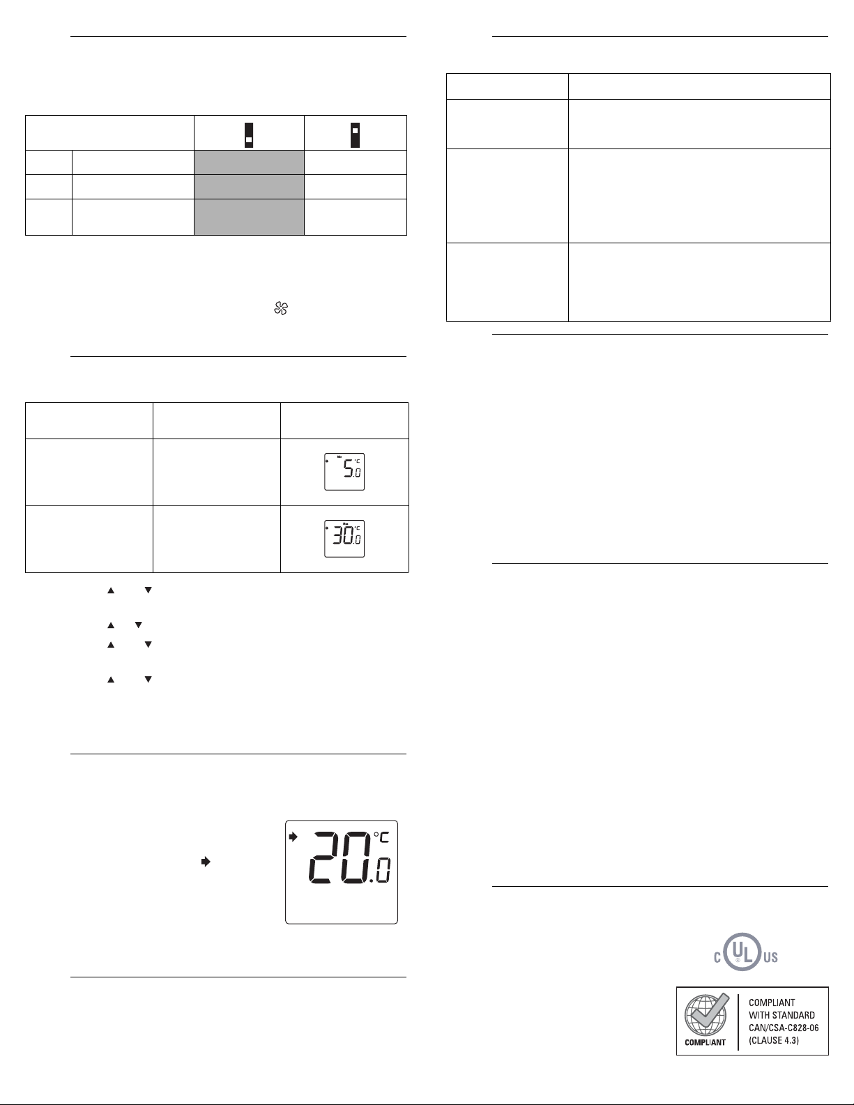
a. The settings are locked. The temperature adjustment buttons
b. Select short cycles (15 seconds) in most cases as it provides bet-
Configuration switches
Switch
1
Keypad lock
2
Cycle length
Temperature
3
display format
only allow you to view the temperature setpoint.
ter temperature control. However, you must select long cycles (5
minutes) if you have a fan-forced heater. is displayed when
long cycles are selected.
a
b
Off On
Short Long
°C °F
Configuration Menu
Parameter Settings
Minimum
setpoint
Maximum
setpoint
• 5 °C - 30 °C
(41 °F - 86 °F)
• 5 °C - 30 °C
(41 °F - 86 °F)
Display and
default setting
Press the and buttons simultaneously for three seconds to
enter the configuration menu.
Press the or button to set the displayed parameter.
Press the and buttons simultaneously for one second to
display the next parameter.
Press the and buttons simultaneously for three seconds to
exit the configuration menu.
NOTE
: The thermostat will automatically save any changes made and
return to its normal display if you do not press any button for one minute.
The thermostat normally displays the actual temperature.
• T o vi ew the setpoint temp erature, press
• To change the setpoint temperature,
• The screen is backlit for 10 seconds when any button is pressed.
During a power outage, the setpoint is saved in memory. You do not
need to adjust the temperature when power returns.
Temperature Display and Setting
once on either temperature adjustment
button. The setpoint temperature will
appear for 5 seconds. The icon
appears when the setpoint is displayed.
press the appropriate button until the
desired value is displayed.
Power Outage
3.
4.
5.
Power supply: 120/208/240 VAC, 60 Hz
Minimum load: 1.25 A / 150 W @ 120 VAC, 60 Hz
Maximum load: 16.7 A / 2000 W @ 120 VAC, 60 Hz
Setpoint range: 5 °C to 30 °C (41 °F to 86 °F)
Display range: 0 °C to 60 °C (32 °F to 140 °F)
Resolution: ± 0.5 °C (± 1 °F)
Storage: -20 °C to 50 °C (-4 °F to 120 °F)
Honeywell warrants this product, excluding battery, to be free from defects in the workmanship
or materials, under normal use and service, for a period of three (3) years from the date of
purchase by the consumer. If at any time during the warranty period the product is determined to
be defective or malfunctions, Honeywell shall repair or replace it (at Honeywell's option).
If the product is defective,
(i) return it, with a bill of sale or other dated proof of purchase, to the place from which you
(ii) contact Honeywell. Honeywell will make the determination whether the product should be
This warranty does not cover removal or reinstallation costs. This warranty shall not apply if it is
shown by Honeywell that the defect or malfunction was caused by damage which occurred
while the product was in the possession of a consumer.
Honeywell's sole responsibility shall be to repair or replace the product within the terms stated
above. HONEYWELL SHALL NOT BE LIABLE FOR ANY LOSS OR DAMAGE OF ANY KIND,
INCLUDING ANY INCIDENTAL OR CONSEQUENTIAL DAMAGES RESULTING, DIRECTLY
OR INDIRECTLY, FROM ANY BREACH OF ANY WARRANTY, EXPRESS OR IMPLIED, OR
ANY OTHER FAILURE OF THIS PRODUCT. Some provinces and state s do not allow the
exclusion or limitation of incidental or consequential damages, so this limitation may not apply to
you.
THIS WARRANTY IS THE ONLY EXPRESS WARRANTY HONEYWELL MAKES ON THIS
PRODUCT. THE DURATION OF ANY IMPLIED WARRANTIES, INCLUDING THE
WARRANTIES OF MERCHANTABILITY AND FITNESS FOR A PARTICULAR PURPOSE, IS
HEREBY LIMITED TO THE THREE-YEAR DURATION OF THIS WARRANTY. Some provinces
and states do not allow limitations on how long an implied warranty lasts, so the above limitation
may not apply to you.
This warranty gives you specific legal rights, and you may have other rights which vary by
province, state or region.
705 Montrichard Avenue,
Saint-Jean-sur-Richelieu, Quebec
J2X 5K8
6.
Canada
1-800-831-2823
aube.service@honeywell.com
www.aubetech.com
Troubleshooting
PROBLEM SOLUTIONS
Thermostat’s
housing is hot.
Wrong temperature
is displayed.
Display disappears
and reappears after
a few minutes.
This is normal. When the thermostat is running
at full capacity, its housing can reach 40 °C
(104 °F).
Rectify if any of the following conditions applies:
• The thermostat is exposed to air draft.
• The sticker on the thermostat’s screen has
not been removed.
• The thermostat is located near or above a
heat source such as a light dimmer.
The thermal protection device on the heater has
temporarily opened. This can happen if the
heater is obstructed by furniture or curtain and
has overheated, or if the heater’s thermal protection device is too sensitive.
Specifications
1.25 A / 260 W @ 208 VAC, 60 Hz
1.25 A / 300 W @ 240 VAC, 60 Hz
16.7 A / 3465 W @ 208 VAC, 60 Hz
16.7 A / 4000 W @ 240 VAC, 60 Hz
Warranty
purchased it, or
returned, or whether a replacement product can be sent to you.
Customer Assistance
7.
8.
9.
10.
TH450 2/2
Printed in USA 06/2011
 Loading...