

Honeywell TH401 Owners Manual
TH401
Non-programmable Thermostat
Thermostat non programmable
Termostato no programable
Owner’s Guide
Guide du propriétaire
Guía del usuario
400-401-000-B

Need Help?
We are here to help. Call 1-800-831-2823.
Besoin d’aide?
Nous sommes là. Composez le 1 800 831-2823.
¿Asistencia?
Estamos aquí para ayudarlo. Llame al 1 800 831-2823.

Owner’s Guide
Table of contents
About your new thermostat ........................................................................................... 1
Temperature display and setting ................................................................................... 2
Removing the faceplate................................................................................................. 3
Wiring ............................................................................................................................ 4
Installing the faceplate................................................................................................... 5
Setup procedure............................................................................................................ 6
Setup menu ................................................................................................................... 7
In case of difficulty......................................................................................................... 8
Specifications ................................................................................................................ 9
Warranty...................................................................................................................... 10
Customer assistance....................................................................................................11
ENGLISH

Owner’s Guide
About your new thermostat
This thermostat can be used to control an electric heating system such as a
baseboard heater, a radiant floor, a radiant ceiling, a convector or a fan-forced
ENGLISH
heater.
The thermostat CANNOT be used with:
• a resistive load under 0.83 A
• a resistive load over 10.4 A
• a system driven by a contactor or a relay (inductive load)
• a central heating system
SUPPLIED PARTS
• One (1) thermostat
• Two (2) 6-32 mounting screws
• Two (2) solderless connectors
1
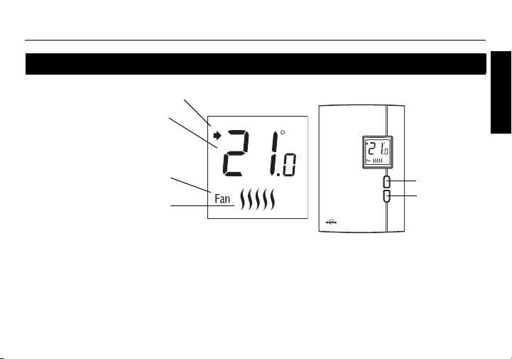
Temperature display and setting
Appears when the setpoint is displayed
Temperature display
Appears when the thermostat
is configured for 5-minute
cycles. The thermostat must be
set to this configuration if it is
controlling a fan-forced heater.
Heating intensity indicator.
(No image appears when
heating is off.)
The thermostat normally displays the actual (ambient) temperature.
• To view the setpoint temperature, briefly press the Up or Down button. The setpoint will
be displayed for 5 seconds and the screen illuminated for 12 seconds.
• To change the setpoint temperature, press the Up or Down button until the desired
value is displayed.
2
Up button
Down button
RTH401
ENGLISH
Owner’s Guide
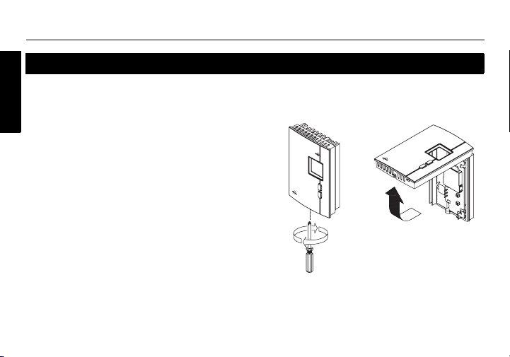
Removing the faceplate
TURN OFF POWER OF THE HEATING SYSTEM AT THE MAIN POWER
PANEL TO AVOID ELECTRIC SHOCK.
ENGLISH
Loosen the screw holding the faceplate to
the base. The screw cannot be completely
removed and remains captive on the base.
Remove the faceplate from the base by
pulling the bottom half.
3
RTH401
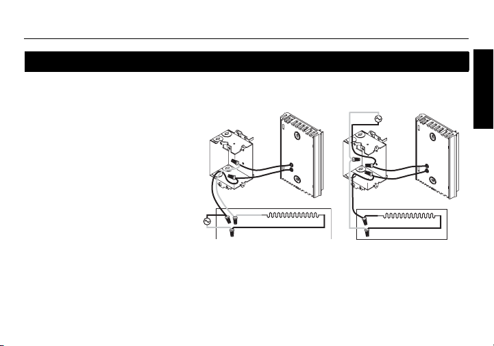
Wiring
Connect any one of
thermostat wires to the
2-wire installation
heater (load) wire and the
other one to the power
supply wire using solderless
connectors for copper wires.
(The thermostat wires are
non-polarized; either wire
can be connected to the load
or to the power supply.)
NOTE: All cables and connections must conform to the local electrical code.
Special CO/ALR solderless connectors must be used when connecting with
aluminium conductors.
4
4-wire installation
ENGLISH
Owner’s Guide
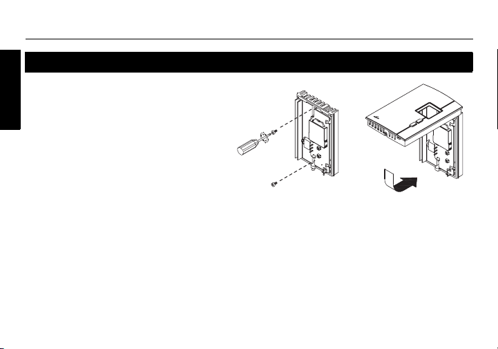
Installing the faceplate
Install the base onto an electrical
box.
ENGLISH
Reinstall the faceplate on the base
and secure it in place with the
screw.
NOTE: Keep the air vents of thermostat clean and unobstructed at
all times.
5

RTH401
Setup procedure
The setup menu is shown on the following page.
n Press the Up and Down buttons simultaneously for three seconds to enter
the setup menu.
o Press the Up or Down button to change the option.
p Press the Up and Down buttons simultaneously for one second to advance
to the next parameter.
q When the last parameter is displayed, press the Up and Down buttons for
three seconds to save any changes and exit the menu.
NOTE:
cally save any changes you have made and will then
If you do not press any button for one minute,
6
the thermostat will automati-
return to its normal display
ENGLISH
.

Owner’s Guide
Setup menu
Parameter Options
ENGLISH
Temperature display format
Display and
default setting
•°C
•°F
Heating cycle
Minimum setpoint 5°C - 20°C (41°F - 68°F)
Maximum setpoint 15°C - 30°C (59°F - 86°F)
• Std (conventional heating): 15 seconds
• Fan (fan-forced heating): 5 minutes
7

In case of difficulty
RTH401
PROBLEM SOLUTIONS
Thermostat is hot. This is normal.
Remediate if any the following conditions exists:
Displayed temperature is wrong.
Display disappears
and reappears after
a few minutes.
• The thermostat is exposed to air draft.
• The sticker on the thermostat’s screen has not been removed.
• The thermostat is located near or above a heat source such as
a light dimmer.
The thermal protection device on the heater has temporarily
opened. This can happen if the heater is obstructed by furniture or
curtain and has overheated, or if the heater’s thermal protection
device is too sensitive.
8
ENGLISH

Owner’s Guide
Specifications
- Supply: 120/240 VAC, 50/60 Hz
- Minimum load: 0.83 A (resistive only)
ENGLISH
- Maximum load: 10.4 A (resistive only)
- Display range: 0°C to 50°C (32°F to 122°F)
- Setpoint range: 5°C to 30°C (40°F to 85°F)
- Storage: -20°C to 50°C (-4°F to 120°F)
- Heating cycle length: 15 seconds / 5 minutes (user-selectable)
- Permanent memory: You do not need to adjust the temperature following a power outage.
200 W @ 240 VAC
100 W @ 120 VAC
2500 W @ 240 VAC
1250 W @ 120 VAC
9
 Loading...