

Honeywell TB6575 SuitePRO, TB8575 SuitePRO Installation Instructions Manual
TB6575/TB8575 SuitePRO™
Digital Fan Coil Thermostats
INSTALLATION INSTRUCTIONS
FEATURES
• Simple, intuitive user interface.
• Pre-installed lead wires for fast installation (TB6575A
and TB6575B models only)
• Backlight display permits easy viewing in any light.
• Four buttons allow manual control of system operation,
fan speed, and temperature setpoint adjustment.
• Digital display of ambient temperature, setpoint, heating
or cooling mode, fan status, and remote setback
• Proportional plus Integral (P+I) control algorithm for
precision temperature regulation.
• Adjustable deadband for auto changeover using the
Heat and Cool setpoint settings.
• Adjustable maximum heating and minimum cooling
setpoint limits using range stops.
PRODUCT DESCRIPTION
The SuitePRO™ is a family of Digital Fan Coil thermostats for
residential and commercial applications such as hotels,
condominiums, school classrooms, etc.
Three models are available for your ap plication:
• TB6575A1000 – 2-pipe or 4-pipe with seasonal/manual/
automatic heat/cool changeover; 120/240 Vac.
• TB6575B1000 – 2-pipe only with seasonal or manual heat/
cool changeover; 120/240 Vac.
• TB8575A1000 – 2-pipe or 4-pipe with seasonal heat/cool
changeover; 24Vac.
All three models are suitable for multiple applications. Changes
in output wiring and external links between wiring terminals
allow you to configure the thermostat for the appropriate
application.
The applications that are available are:
• Heating or Cooling only
• Two pipes: Heat or Cool with Manual Changeover
• Two pipes: Heat or Cool with Seasonal Changeover
(requires optional pipe sensor)
• Two pipes: Heat or Cool with Auxiliary Heat and Manual or
Seasonal Changeover (requires optional pipe sensor)
• Four pipes: Mixed Manual and Auto Changeover
• Four pipes: Manual Changeover
• Four pipes: Auto Changeover
The fan is controlled from the thermostat. The Low, Mid, High, or
Auto fan settings are easily made with a press of a key.
Valves and auxiliary electric heaters can be controlled using a
relay or contactor controlled by the system switch.
• Installer Setup mode allows changes of operating
parameters.
• EEPROM permanently retains user settings, including
setpoints, during power loss (no batteries required).
• Selectable °C or °F display via Installer Setup.
• Displayable pipe sensor temperature readout to aid in
troubleshooting.
• Automatic pipe purge of five minutes, once every 24
hours, to ensure unrestricted flow (only when used with
optional pipe sensor).
• Fan motor always begins on high speed to ensure
sufficient torque at startup.
• Option to wire a remote indoor temperature sensor.
• Freeze protect algorithm turns on heat when needed.
• Energy Saving Options:
• Activity Sensing- sets back thermostat to Economy
mode when there is no activity with the thermostat
(4, 12, or 24 hours selectable).
• Remote Setback Inputs- receives dry contact input
from a time switch, occupancy sensor, or hotel card
key to set back thermostat to Economy mode.
• Auto Fan Reset - eliminates the fan from being run
all the time by automatically setting the fan to Auto
(2 or 4 hour selectable).
• VersaSpeed™ fan ramp algorithm automatically
adjusts fan speed (low, medium, and high).
Product Description ................................................... 1
Features .................................................................... 1
Specifications ............................................................ 2
Ordering Information ................................................. 2
Installation ................................................................. 3
Setup ......................................................................... 9
Operation .................................................................. 12
Troubleshooting ......................................................... 14
Contents
62-0278-01
TB6575/TB8575 SUITEPRO™ DIGITAL FAN COIL THERMOSTATS ORDERING INFORMATION
ORDERING INFORMATION
When purchasing replacement and modernization products from
your TRADELINE® wholesaler or distributor, refer to the
TRADELINE® catalog or price sheets for complete ordering
number. Orders can also be placed at http://customer.honeywell.
com.
If you have additional questions, need further information, or
would like to comment on our products or services, please write
or phone:
1. Your local Honeywell Autom ation and Control Products
sales office (check the white pages of your phone
directory).
2. Honeywell Customer Care
1885 Douglas Drive North
Minneapolis, Minnesota 55422-4386
(763) 954-5720
3. In Canada–Honeywell Limited/Honeywell Limitée, 35
Dynamic Drive, Toronto, Ontario M1V 4Z9.
International sales and service offices in all principal cities of the
world. Manufacturing in Australia, Canada, Finland, France,
Germany, Japan, Mexico, Netherlands, Spain, Taiwan, United
Kingdom, U.S.A.
SPECIFICATIONS
Supply Voltages:
TB6575A1000 and TB6575B1000:
• 120 Vac ±10% at 50/60Hz
• 240 Vac ±10% at 50/60Hz
TB8575A1000:
• 20 to 30 Vac at 50/60Hz (using 24 Vac, Class 2,
NEMA rated transformer)
Safety Fuse: 15 A, 250 Vac. If the safety fuse blows, the
thermostat must be replaced. The fuse is not field
replaceable.
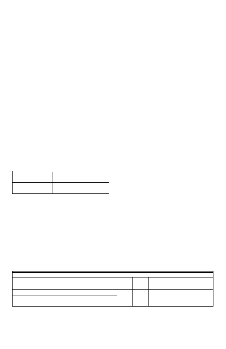
Electrical Ratings:
Fan Relay 1.0 A 6.0 A 3.0 A
Heat/Cool Relay 1.0 A 1.0 A 1.0 A
Environmental Ratings:
Temperature:
Humidity: 5% to 90% RH, non-condensing.
Onboard Temperature Sensor:
Type: 10K NTC
Working Range: 18°C to 49°C (0°F to 120°F)
Display Range: 0°C to 37°C (32°F to 99°F)
Accuracy ±2.0°F at 70°F
Remote Temperature Sensor (optional):
Type: 20K NTC
Working Range: 18°C to 49°C (0°F to 120°F)
Display Range: 0°C to 37°C (32°F to 99°F)
Accuracy ±2.0°F at 70°F
Table 1. Electrical Ratings.
Component
Operating Range: 18°C to 49°C (0°F to 120°F).
Shipping and Storage Range: -29°C to 49°C (-20°F to
120°F).
Amps (inductive) for:
24 Vac 120 Va c 2 40 Vac
Remote Pipe Sensor (optional):
Type: 20K NTC
Working Range: 0°C to 93°C (32°F to 199°F)
Display Range: 0°C to 93°C (32°F to 199°F)
Accuracy ±5.0°F over the temperature sensing range
Remote Setback Input: Dry contact, maximum resistance of
100 ohms. TB6575 – 9Vdc, < 4 mA; TB8575 – 16 Vdc, < 5 mA.
Note Electrical WARNING on page 3.
Remote Setback Range:
Heating: 10°C to 21°C (50°F to 70°F).
Cooling: 22°C to 32°C (72°F to 90°F).
Enclosure: Plastic (cover, sub-base, and optional adaptor plate)
Junction Box Mounting: Direct mounting on a horizontal single
gang NEMA 2 x 4 in. surface mount electrical box, or on 4 x 4 in.
box or vertical 2 x 4 in. surface mount electrical box with the
optional 50033847-001 adapter plate.
Dimensions: See Fig. 1 on page 3.
Wiring: 11 screw-in terminals located on the sub-base capable
of accepting up to 2 x 18 AWG (0.8 sq. mm), 1 x 16 AWG (1.3 sq.
mm), or 1 x 14 AWG (2.1 sq. mm) wires. Accepts stranded or
unstranded 14-28 gauge wire.
NOTES:
1. The TB6575A1000 model is pre-fitted with color-coded
fly leads (16 AWG) attached to seven terminals.
2. The TB6575B1000 model is pre-fitted with color-coded
fly leads (16 AWG) attached to six terminals.
3. The TB8575A1000 model does not have fly leads
attached to any terminals.
4. See Table 3 on page 5 for fly lead usage.
Minimum Operational Life (at maximum load):
Thermostat contacts: 100,000 cycles
Approvals:
CSA Certified C/US for Canada and the U.S.A. Meets the
same requirements as UL-873.
FCC Part 15 Class B
Accessories:
• 50033847-001 – Adapter plate for mounting on a vertical 2 x 4
in. single-gang or double-gang NEMA standard vertical switch
box.
• TR21 – 20K Ohm NTC Non-Linear Remote temperature
sensor.
Other acceptable remote temperature sensors are —
• 20K Ohm: C7041B2005, C7041B2013, C7041C2003,
C7041P2004, C7770A1006, C7772A1004, and
C7772A1012
• 10K Ohm (for averaging only): TR21-A
• PS20 – Remote pipe sensor (20K Ohm)
• W6380B1005 – Fan Coil Unit Relay Control Center
Models, Applications, and Features
Table 2 identifies the applications and features of each model.
Table 2. Applications and Features
Models Applications Features
TB6575A1000 All 2 or 4 120 or 240 Vac 5
TB6575B1000 Heat or Cool 2 120 or 240 Vac 4
TB8575A1000 All 2 or 4 24 Vac 5
a
The five relays are wired via terminals W, Y, Gh, Gm, and Gl. Relay 1 controls Heat open (W) or Cool open (Y). Relay 2 controls Cool
open or Electrical heater output (Y/A). Relays 3, 4, and 5 control the High, Medium, and Low fan speeds respectively (Gh, Gm, and
Gl).
NOTE: In 2-pipe configurations without Auxiliary Heat, only 4 relays are used; relay 2 (Y/A) is not used.
b
Pipe sensor is optional.
62-0278—01 2
Heat/Cool/
Auto
Pipes Voltage Number
of Relays
Energy
a
Savings
Fan:
On, Auto,
Input
or 3 speed
Yes Ye s Yes Yes Yes Yes
Manual/Auto
Changeover
Remote
Sensor
Back
Light
Pipe
Sensor
b
INSTALLATION TB6575/TB8575 SUITEPRO™ DIGITAL FAN COIL THERMOSTATS
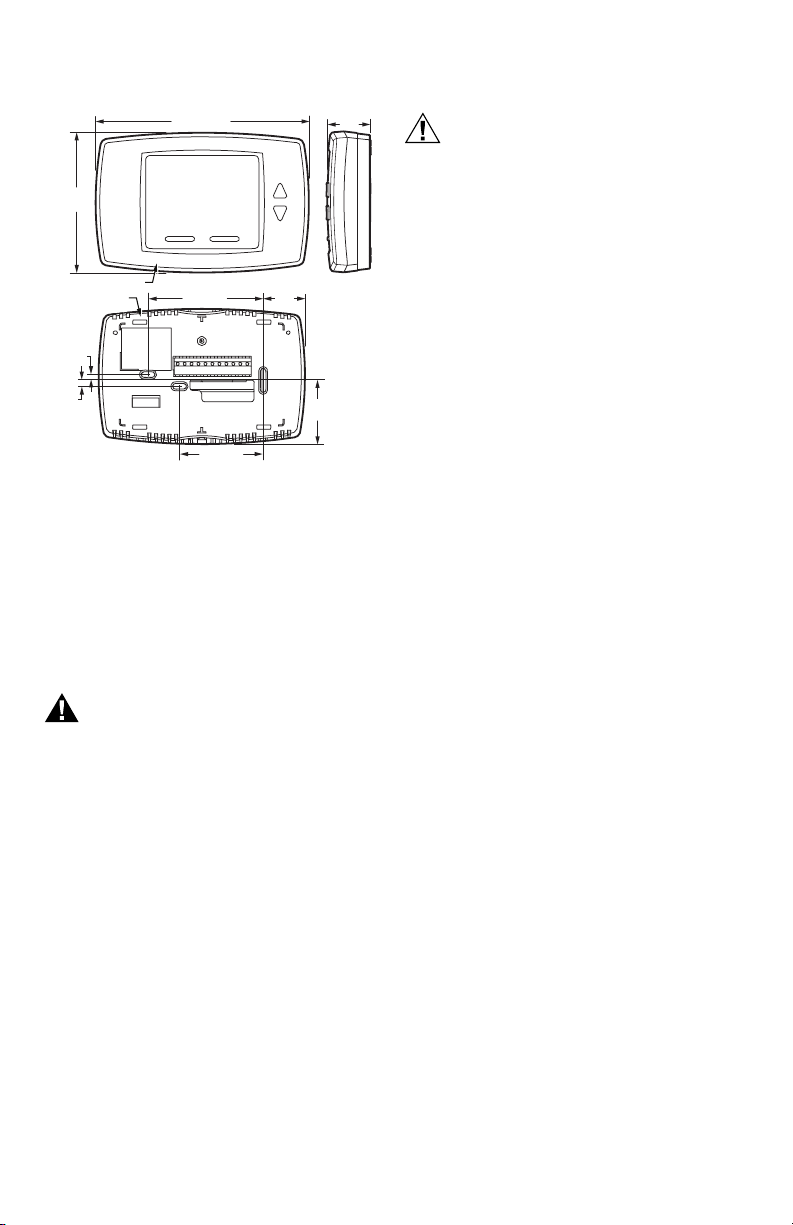
Dimensions
1-3/4
(44)
1-1/8
(29)
M27589
5-13/16 (148)
3-13/16
(97)
THERMOSTAT
SUB-BASE
5/32
(4)
5/32
(4)
Fig. 1. Dimensions in inches and mm.
3-1/4 (83)
UP
2-3/8 (60)
1-3/16
(30)
INSTALLATION
When Installing this Product…
1. Read these instructions carefully. Failure to follow them
could damage the product or cause a hazardous
condition.
2. Check the ratings given in the instructions and on the
product to make sure the product is suitable for your
application.
3. Installer must be a trained and experienced service
technician.
WARNING
Risk of electrical shock.
Can cause severe injury, property damage or
death.
Disconnect power supply before installation and
before servicing.
IMPORTANT
The thermostats are line voltage powered devices. All
wiring must comply with national and local electrical
codes, ordinances and regulations. Provide disconnect
means and overload protection, as required.
The TB8575A1000 thermostat must be powered by an
Approved 24 Vac, Class 2, NEMA rated transformer
(such as a W6380 Relay Control Center).
Location
The thermostats are the temperature control element in a fan coil
or air-conditioning system. They must be located about 1.5m
(5 ft.) above the floor, in a position with good air circulation, to
sense room temperature.
IMPORTANT
Do not mount device where it can be affected by:
1. Drafts or dead spots behind doors or in corners.
2. Hot or cold air from ducts.
3. Radiant heat from the sun or appliances.
4. Unheated (uncooled) areas such as an outside wall
behind the thermostat.
5. Concealed pipes or chimneys.
Mounting and Wiring
CAUTION
Equipment Damage Hazard.
Operation at low temperatures can cause fan
coil damage.
This thermostat is not a safety device. Do not use
it where the space temperature is outside of the
device operating range.
A display of two dashes, – –, for the Room Temp
display indicates a sensor failure or a
temperature outside of the thermostat operating
range of 18°C to 49°C (0°F to 120°F). With – –
displayed, the thermostat ceases to operate.
When the temperature returns to within its
operating limits, the thermostat returns to
operation.
The optional freeze protect feature should be used
if low temperatures can occur.
The thermostat must be mounted flush to the wall. The
thermostat can be mounted directly to a 2 x 4 in. horizontal
junction box (see Fig. 2 on page 4). An optional adaptor plate
(50033847-001) can be used with a 4 x 4 in. or a vertical junction
box for which mounting screws are supplied (see Fig. 3 on
page 4).
1. Prepare the supply wires:
a. Mounting on a 4 x 4 in. or vertical 2 x 4 in. junction
box:
(1) Feed the supply wires through the junction box
and the opening in the adaptor plate.
(2) Affix the adaptor plate to the junction box using
the screws provided.
b. Mounting on a horizontal 2 x 4 in. junction box:
Feed the supply wires through the opening of the
junction box.
2. Attach the supply wires:
a. For the TB6575A1000 and TB6575B1000 models:
(1) Push the fly lead wires through the wiring access
hole in the sub-base.
(2) Attach the fly lead wires to the supply wires using
wire nuts (not provided).See Table 3 on page 5 for
terminal and lead identification.
(3) Push the fly lead and supply wires back into the
junction box.
b. For the TB8575A1000 model (which does not have
pre-wired fly leads):
(1) Attach the supply wires directly to the terminals on
the sub-base. See Table 3 on page 5 for terminal
identification.
(2) Push the supply wires back into the junction box.
3. Mount the sub-base:
a. Mounting on a 4 x 4 in. or vertical 2 x 4 in. junction
box:
Align the two holes at the top edges of the sub-base
with the two pins on the adaptor plate. Attach the
sub-base to the adaptor plate using the screws
provided.
b. Mounting on a horizontal 2 x 4 in. junction box:
Attach the sub-base to the junction box using the
screws provided.
4. Thoroughly check the wiring to the sub-base before finally
mounting the thermostat on the wall.
5. Center the thermostat body over the sub-b ase, and press
down firmly to engage the four tabs on the sub-base and
snap the thermostat body into place.
6. Use the provided safety screw to secure the thermostat
main body to the sub-base.
7. If using the adaptor plate, press the adaptor plate screw
cover into place.
3 62-0278—01
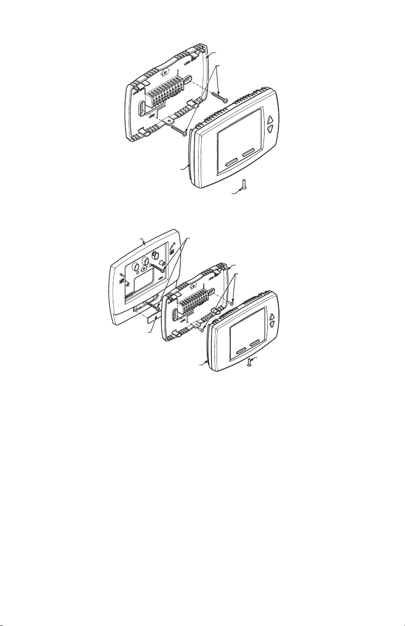
TB6575/TB8575 SUITEPRO™ DIGITAL FAN COIL THERMOSTATS INSTALLATION
SUBBASE
MOUNT SUBBASE TO
HORIZONTAL 2X4
JUNCTION BOX USING
TWO SCREWS
SNAP MAIN BODY
ONTO SUBBASE
INSERT SCREW TO LOCK
MAIN BODY TO SUBBASE
Fig. 2. Mounting sub-base and thermostat to 2 x 4 in. junction box.
ADAPTOR
PLATE
ADAPTOR
PLATE
SCREW HEAD
COVER
SNAP MAIN BODY
ONTO SUB-BASE
NOTE: MIDDLE HOLES OF ADAPTOR PLATE ARE USED FOR MOUNTING
TO A 2X4 VERTICAL JUNCTION BOX. USE OUTER HOLES FOR
MOUNTING TO A 4X4 WIRING BOX.
Fig. 3. Mounting sub-base and thermostat using the adaptor plate (50033847-001).
Terminal Wiring
Table 3 on page 5 provides the terminal wiring for each model
and application.
NOTE: The TB6575A1000 and TB6575B1000 models have
color coded fly leads attached to the terminals. Refer
to Table 3 for the color codes.
M27590
MOUNT ADAPTOR PLATE ONTO
4X4 WIRING BOX OR 2X4
VERTICAL JUNCTION BOX
USING TWO SCREWS
SUB-BASE
MOUNT SUB-BASE
ONTO WALL PLATE
USING TWO SCREWS
INSERT SCREW
TO LOCK MAIN
BODY TO
SUB-BASE
M27591
The Terminal Identifiers in Table 3 have the following meaning:
• C: Common 24 Vac
• Gh: High speed fan relay
• Gl: Low speed fan relay
• Gm: Medium speed fan relay
• L: Line voltage power (120/240 Vac)
• N: Line voltage ground (120/240 Vac)
• Ps: Pipe sensor (optional)
• R: 24 Vac power
• Rs: Remote sensor (optional)
• SB: Remote setback (optional)
• Sc: Ground (required if remote sensor, pipe sensor, and/or
remote setback are connected)
• W/Y: W = Heating; Y = Cooling (2 pipe only)
• Y/A: Y = Cooling; A = Electrical heater output
62-0278—01 4
INSTALLATION TB6575/TB8575 SUITEPRO™ DIGITAL FAN COIL THERMOSTATS
Table 3. Terminal Wiring.
Model Application
12 34567891011
TB6575A1000 — 120/240 Vac
Terminal Identifier
Fly lead wire color
2 pipes; Heat only
LW/Y Y/AGlGmGhNRs
Black Orange Yellow Red Blue Brown White None
f
W !! ! !
!
2 pipes; Cool only ! Y !! ! ! ORO
2 pipes; Heat or Cool with Manual Changeover ! W/Y !! ! ! ORO
2 pipes; Heat or Cool with Seasonal Changeover ! W/Y !! ! ! ORO!
4 pipes; Heat and Cool with Manual Changeover ! WY!! ! ! OR O
4 pipes; Heat and Cool with Auto Changeover ! WY!! ! ! ORO
2 pipes; Heat or Cool with Auxiliary Heat ! W/Y A !! ! ! ORO!
4 pipes; Heat and Cool with Manual Changeover or Auto Changeover ! WY!! ! ! ORO
TB6575B1000 — 120/240 Vac
Terminal Identifier
Fly lead wire color
LW/Y n/a
Black Orange Red Blue Brown White None
2 pipes; Heat only ! W !! ! ! ORO
2 pipes; Cool only ! Y !! ! ! ORO
2 pipes; Heat or Cool with Manual Changeover ! W/Y !! ! ! ORO
2 pipes; Heat or Cool with Seasonal Changeover ! W/Y !! ! ! ORO!
TB8575A1000 — 24 Vac
Terminal Identifier
j
RW/YY/AGlGmGh CRsaScbSBcPs
2 pipes; Heat only ! W !! ! ! ORO
2 pipes; Cool only ! Y !! ! ! ORO
2 pipes; Heat or Cool with Manual Changeover ! W/Y !! ! ! ORO
2 pipes; Heat or Cool with Seasonal Changeover ! W/Y !! ! ! ORO!
4 pipes; Heat and Cool with Manual Changeover ! WY!! ! ! OR O
4 pipes; Heat and Cool with Auto Changeover ! WY!! ! ! ORO
2 pipes; Heat or Cool with Auxiliary Heat ! W/Y A !! ! ! ORO!
4 pipes; Heat and Cool with Manual Changeover or Auto Changeover ! WY!! ! ! ORO
a
Rs; Remote sensor is optional.
b
Required when Rs, SB, or Ps is wired.
c
SB; Remote setback is optional.
d
Pipe sensor: Discrete, Analog, or Aquastat®.
e
These terminals (8, 9, 10, and 11) do not have lead wires attached to them.
f
A check mark (!) indicates the terminal is used in that application. Rs and SB terminal connections are optional. If a terminal is left
blank, it is not used in that application.
g
O = Optional
h
R = Required if Rs, SB, or Ps is wired.
i
Terminal 3 is not used on the TB6575B1000 model.
j
The TB8575A1000 model does not have fly lead wires attached to any terminals.
Ter min als
a
Sc
g
R
O
i
Gl Gm Gh N RsaScbSBcPs
b
c
SB
Ps
e
h
O
e
d
d
d
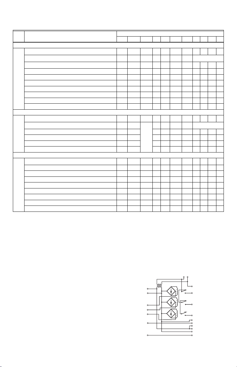
Accessory Wiring
Fan-Relay Control Center Wiring
The fan coil thermostats are typically used with load relays to
switch line voltage loads. Honeywell offers a convenient fan coil
relay center, the W6380B1005, which provides 24 Vac power,
three interlocked fan relays, and wiring center terminations for
valve, relay and contactor loads. The W6380 schematic is
illustrated in Fig. 4.
L2
L1
24 VAC
P10
P1
P2
HI
P4
MED
P5
LO
P6
HEAT
P8
COOL
COM
HI
MED
LO
PI
HEAT VALVE
P13
P14
COOL VALVE
P15
M27588
Fig. 4. W6380 wiring diagram.
5 62-0278—01
 Loading...