

Honeywell TB6575B1000/U Installation Instructions Manual
TB6575/TB8575 Digital Fan Coil
Thermostats
INSTALLATION INSTRUCTIONS
FEATURES
• Simple, intuitive user interface.
• Pre-installed lead wires for fast installation
(TB6575A and TB6575B models only)
• Backlight display permits easy viewing in any
light.
• Four buttons allow manual control of system
operation, fan speed, and temperature setpoint
adjustment.
• Digital display of ambient temperature, setpoint,
heating or cooling mode, fan status, and remote
setback
• Proportional plus Integral (P+I) control algorithm
for precision temperature regulation.
PRODUCT DESCRIPTION
The TB6575 and TB8575 are a family of Digital Fan Coil
thermostats for residential and commercial applications
such as hotels, condominiums, school classrooms, etc.
Three models are available for your application:
• TB6575A1000 – 2-pipe or 4-pipe with seasonal/
manual/automatic heat/cool changeover; 120/240
Vac .
• TB6575B1000 – 2-pipe only with seasonal or manual
heat/cool changeover; 120/240 Vac.
• TB8575A1000 – 2-pipe or 4-pipe with seasonal heat/
cool changeover; 24Vac.
All three models are suitable for multiple applications.
Changes in output wiring and external links between
wiring terminals allow you to configure the thermostat for
the appropriate application.
The applications that are available are:
• Heating or Cooling only
• Two pipes: Heat or Cool with Manual Changeover
• Two pipes: Heat or Cool with Seasonal Changeover
(requires optional pipe sensor)
• Two pipes: Heat or Cool with Auxiliary Heat and
Manual or Seasonal Changeover (requires optional
pipe sensor)
• Four pipes: Mixed Manual and Auto Changeover
• Four pipes: Manual Changeover
• Four pipes: Auto Changeover
The fan is controlled from the thermostat. The Low,
Medium, High, or Auto fan settings are easily made with
a press of a key.
Valves and auxiliary electric heaters can be controlled
using a relay or contactor controlled by the system
switch.
• Single Setpoint and Heat/Cool setpoint methods
for 4-pipe auto changeover.
• Adjustable maximum heating and minimum
cooling setpoint limits using range stops.
• EEPROM permanently retains user settings,
including setpoints, during power loss (no
batteries required).
• Selectable °C or °F display via Setup button on
thermostat.
• Displayable pipe sensor temperature readout to
aid in troubleshooting.
• Selectable to allow the fan motor to always begin
on high speed to ensure sufficient torque at
startup.
• Option to wire a remote indoor temperature
sensor.
• Freeze protect algorithm turns on heat when
needed.
• Economy Setback options via dry contact or
Activity Sensing
• Advanced fan control with VersaSpeed™ fan ramp
algorithm and Auto Fan Reset
Contents
Product Description ................................................... 1
Features .................................................................... 1
Specifications ............................................................ 2
Installation ................................................................. 3
Setup ......................................................................... 10
Operation ................................................................... 14
Troubleshooting ......................................................... 17
Place Bar Code Here
62-0311-05
TB6575/TB8575 DIGITAL FAN COIL THERMOSTATS
SPECIFICATIONS
Supply Voltages:
TB6575A1000 and TB6575B1000:
• 120 Vac ±10% at 50/60Hz
• 240 Vac ±10% at 50/60Hz
TB8575A1000:
• 20 to 30 Vac at 50/60Hz (using 24 Vac, Class 2,
NEMA rated transformer)
Safety Fuse: 15 A, 250 Vac. If the safety fuse blows, the
thermostat must be replaced. The fuse is not field
replaceable.
Electrical Ratings: (see Table 1).
Table 1. Electrical Ratings.
Amps (inductive) for:
Component
Fan Relay 1.0 A 6.0 A 3.0 A
Heat/Cool Relay 1.0 A 1.0 A 1.0 A
Environmental Ratings:
Temperature:
Operating Range: 18°C to 49°C (0°F to 120°F).
Shipping and Storage Range: -29°C to 49°C (-20°F to
120°F).
Humidity: 5% to 90% RH, non-condensing.
Onboard Temperature Sensor:
Typ e: 10 K NT C
Working Range: 18°C to 49°C (0°F to 120°F)
Display Range: 0°C to 37°C (32°F to 99°F)
Accuracy ±2.0°F at 70°F
Remote Temperature Sensor (optional):
Typ e: 20 K NT C
Working Range: 18°C to 49°C (0°F to 120°F)
Display Range: 0°C to 37°C (32°F to 99°F)
Accuracy ±2.0°F at 70°F
Remote Pipe Sensor (optional):
Typ e: 20 K NT C
Working Range: 0°C to 93°C (32°F to 199°F)
Display Range: 0°C to 93°C (32°F to 199°F)
Accuracy ±5.0°F over the temperature sensing range
Remote Setback Input: Dry contact, maximum
resistance of 100 ohms. TB6575 – 9Vdc, < 4 mA; TB8575
– 16 Vdc, < 5 mA. Note Electrical WARNING on page 3.
Remote Setback Range:
Heating: 10°C to 21°C (50°F to 70°F).
Cooling: 22°C to 32°C (72°F to 90°F).
Models
TB6575A1000 All 2 or 4 120 or
TB6575B1000 Heat or
TB8575A1000 All 2 or 4 24 Vac 5
24 Vac 120 Vac 240 Vac
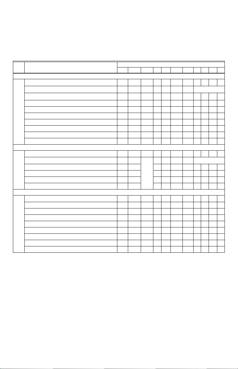
Table 2. Applications and Features
Applications Features
Heat/Cool/
Auto
Cool
Pipes Voltage Number
of Relays
240 Vac
2120 or
240 Vac
5
4
Enclosure: Plastic (cover, sub-base, and optional adap-
tor plate)
Junction Box Mounting: Direct mounting on a horizontal
single gang NEMA 2 x 4 in. surface mount electrical box,
or on 4 x 4 in. box or vertical 2 x 4 in. surface mount
electrical box with the optional 50033847-001 adapter
plate.
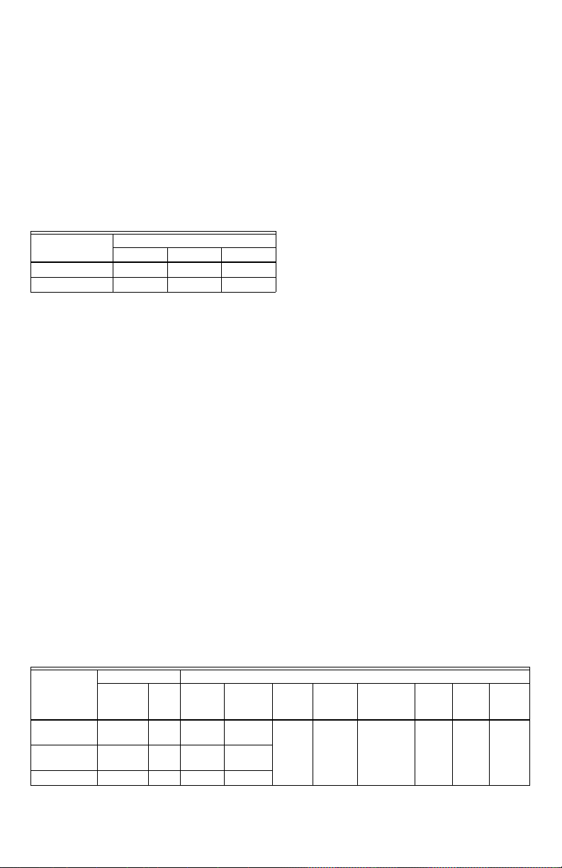
Dimensions: See Fig. 1 on page 3.
Wiring: 11 screw-in terminals located on the sub-base
capable of accepting up to 2 x 18 AWG (0.8 sq. mm), 1 x
16 AWG (1.3 sq. mm), or 1 x 14 AWG (2.1 sq. mm) wires.
Accepts stranded or unstranded 14-28 gauge wire.
NOTES:
1. The TB6575A1000 model is pre-fitted with colorcoded fly leads (16 AWG) attached to seven
terminals.
2. The TB6575B1000 model is pre-fitted with colorcoded fly leads (16 AWG) attached to six
terminals.
3. The TB8575A1000 model does not have fly
leads attached to any terminals.
4. See Table 3 on page 5 for fly lead usage.
Minimum Operational Life (at maximum load):
Thermostat contacts: 100,000 cycles
Approvals:
CSA Certified C/US for Canada and the U.S.A. Meets
the same requirements as UL-873.
FCC Part 15 Class B
Accessories:
• 50033847-001 – Adapter plate for mounting on a
vertical 2 x 4 in. single-gang or double-gang NEMA
standard vertical switch box (6 1/4 in. (158 mm) x 5 1/
16 in. (128 mm) x 13/22 in. (10 mm)).
• TR21 – 20K Ohm NTC Non-Linear Remote
temperature sensor.
Other acceptable remote temperature sensors are —
• 20K Ohm: C7041B2005, C7041B2013, C7041C2003,
C7041P2004, C7770A1006, C7772A1004, and
C7772A1012
• 10K Ohm (for averaging only): TR21-A
• PS20 – Remote pipe sensor (20K Ohm)
• W6380B1005 – Fan Coil Unit Relay Control Center
• WSK-24 - Wireless Occupancy Solution (Receiver,
occupancy sensor and door sensor)
Models, applications, and features:
Table 2 identifies the applications and features of each
model.
Energy
a
Savings
Input
Fan: On,
Auto, or
3 speed
Manual/
Auto
Changeover
Remote
Sensor
Back
Light
Yes Yes Yes Yes Yes Yes
Pipe
Sensor
b
62-0311—05 2
TB6575/TB8575 DIGITAL FAN COIL THERMOSTATS
a
The five relays are wired via terminals W, Y, Gh, Gm, and Gl. Relay 1 controls Heat open (W) or Cool open (Y). Relay
2 controls Cool open or Electrical heater output (Y/A). Relays 3, 4, and 5 control the High, Medium, and Low fan
speeds respectively (Gh, Gm, and Gl).
NOTE: In 2-pipe configurations without Auxiliary Heat, only 4 relays are used; relay 2 (Y/A) is not used.
b
Pipe sensor is required for 2 pipe auto changeover and 2 pipe auxiliary heat applications.
IMPORTANT
Do not mount the device where it can be affected by:
1. Drafts or dead spots behind doors or in corners.
2. Hot or cold air from ducts.
3. Radiant heat from the sun or appliances.
4. Unheated (uncooled) areas such as an outside
wall behind the thermostat.
5. Concealed pipes or chimneys.
3-13/16
(97)
5-13/16 (148)
1-1/8
(29)
Mounting and Wiring
5/32
5/32
(4)
(4)
THERMOSTAT
SUB-BASE
3-1/4 (83)
UP
2-3/8 (60)
1-3/16
(30)
1-3/4
(44)
M27589
Fig. 1. Dimensions in inches (mm).
INSTALLATION
When Installing this Product…
1. Read these instructions carefully. Failure to follow
them could damage the product or cause a hazardous condition.
2. Check the ratings given in the instructions and on
the product to make sure the product is suitable for
your application.
3. Installer must be a trained and experienced service
technician.
WARNING
Risk of electrical shock.
Can cause severe injury, property damage or
death.
Disconnect power supply before installation and
before servicing.
IMPORTANT
The thermostats are line voltage powered devices. All
wiring must comply with national and local electrical
codes, ordinances and regulations. Provide disconnect
means and overload protection, as required.
The TB8575A1000 thermostat must be powered by an
Approved 24 Vac, Class 2, NEMA rated transformer
(such as a W6380 Relay Control Center).
Location
The thermostats are the temperature control element in a
fan coil or air-conditioning system. They must be located
about 1.5m (5 ft.) above the floor, in a position with good
air circulation, to sense room temperature.
CAUTION
Equipment damage hazard.
Operation at low temperatures can cause fan
coil damage.
This thermostat is not a safety device. Do not use
it where the space temperature is outside of the
device operating range.
A display of two dashes, – –, for the Room Temp
display indicates a sensor failure or a temperature
outside of the thermostat operating range of 18°C
to 49°C (0°F to 120°F). With – – displayed, the
thermostat ceases to operate. When the
temperature returns to within its operating limits,
the thermostat returns to operation.
The optional freeze protect feature should be used
if low temperatures can occur.
The thermostat must be mounted flush to the wall. The
thermostat can be mounted directly to a 2 x 4 in.
horizontal junction box (see Fig. 2 on page 4). An optional
adaptor plate (50033847-001) can be used with a 4 x 4 in.
or a vertical junction box for which mounting screws are
supplied (see Fig. 3 on page 4).
1. Prepare the supply wires:
a. Mounting on a 4 x 4 in. or vertical 2 x 4 in.
junction box:
(1) Feed the supply wires through the junction
box and the opening in the adaptor plate.
(2) Affix the adaptor plate to the junction box
using the screws provided.
b. Mounting on a horizontal 2 x 4 in. junction box:
Feed the supply wires through the opening of the
junction box.
2. Attach the supply wires:
a. For the TB6575A1000 and TB6575B1000
models:
(1) Push the fly lead wires through the wiring
access hole in the sub-base.
(2) Attach the fly lead wires to the supply wires
using wire nuts (not provided).See Table 3
on page 5 for terminal and lead identification.
(3) Push the fly lead and supply wires back into
the junction box.
b. For the TB8575A1000 model (which does not
have pre-wired fly leads):
3 62-0311—05
TB6575/TB8575 DIGITAL FAN COIL THERMOSTATS
(1) Attach the supply wires directly to the termi-
nals on the sub-base. See Table 3 on
page 5 for terminal identification.
(2) Push the supply wires back into the junction
3. Mount the sub-base:
box.
a. Mounting on a 4 x 4 in. or vertical 2 x 4 in. junc-
tion box:
Align the two holes at the top edges of the subbase with the two pins on the adaptor plate.
Attach the sub-base to the adaptor plate using
the screws provided.
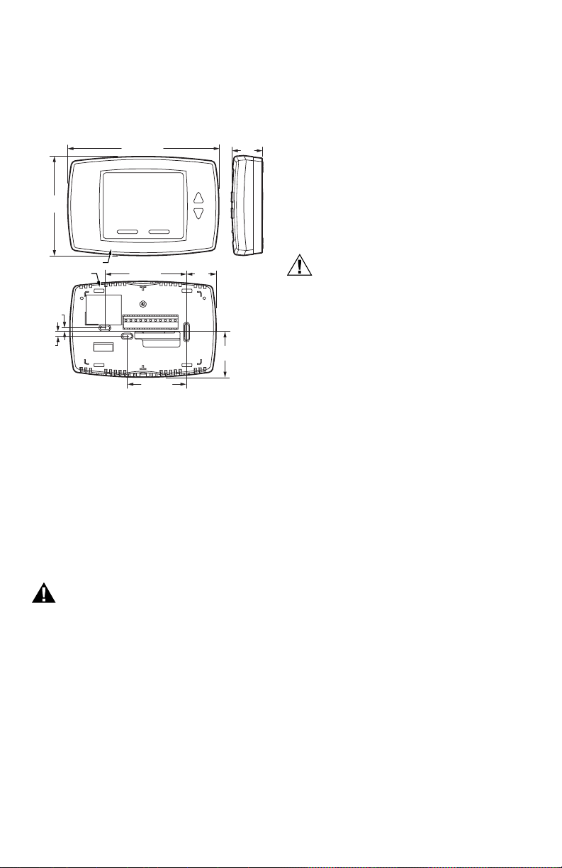
b. Mounting on a horizontal 2 x 4 in. junction box:
SNAP MAIN BODY
ONTO SUBBASE
Fig. 2. Mounting sub-base and thermostat to 2 x 4 in. junction box.
4. Thoroughly check the wiring to the sub-base before
5. Center the thermostat body over the sub-base, and
6. Use the provided safety screw to secure the ther-
7. If using the adaptor plate, press the adaptor plate
SUBBASE
MOUNT SUBBASE TO
HORIZONTAL 2X4
JUNCTION BOX USING
TWO SCREWS
INSERT SCREW TO LOCK
MAIN BODY TO SUBBASE
Attach the sub-base to the junction box using
the screws provided.
finally mounting the thermostat on the wall.
press down firmly to engage the four tabs on the
sub-base and snap the thermostat body into place.
mostat main body to the sub-base.
screw cover into place.
M27590
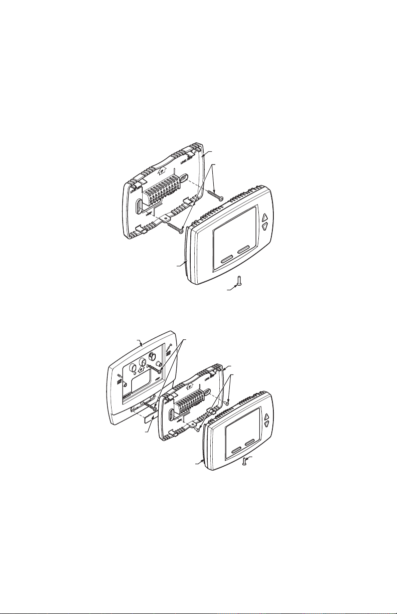
ADAPTOR
PLATE
ADAPTOR
PLATE
SCREW HEAD
COVER
SNAP MAIN BODY
ONTO SUB-BASE
NOTE: MIDDLE HOLES OF ADAPTOR PLATE ARE USED FOR MOUNTING
TO A 2X4 VERTICAL JUNCTION BOX. USE OUTER HOLES FOR
MOUNTING TO A 4X4 WIRING BOX.
MOUNT ADAPTOR PLATE ONTO
4X4 WIRING BOX OR 2X4
VERTICAL JUNCTION BOX
USING TWO SCREWS
Fig. 3. Mounting sub-base and thermostat using the adaptor plate (50033847-001).
Terminal Wiring
Table 3 provides the terminal wiring for each model and
application.
NOTE: The TB6575A1000 and TB6575B1000 models
have color coded fly leads attached to the terminals. Refer to Table 3 for the color codes.
62-0311—05 4
SUB-BASE
MOUNT SUB-BASE
ONTO WALL PLATE
USING TWO SCREWS
INSERT SCREW
TO LOCK MAIN
BODY TO
SUB-BASE
M27591
The Terminal Identifiers in Table 3 have the following
meaning:
• C: Common 24 Vac
• Gh: High speed fan relay
• Gl: Low speed fan relay
• Gm: Medium speed fan relay
• L: Line voltage power (120/240 Vac)
TB6575/TB8575 DIGITAL FAN COIL THERMOSTATS
• N: Line voltage ground (120/240 Vac)
• Ps: Pipe sensor (optional)
• R: 24 Vac power
• Rs: Remote sensor (optional)
• Sc: Ground (required if remote sensor, pipe sensor,
and/or remote setback are connected)
• W/Y: W = Heating; Y = Cooling (2 pipe only)
• Y/A: Y = Cooling; A = Electrical heater output
• SB: Remote setback (optional)
Table 3. Terminal Wiring.
Model Application
TB6575A1000 — 120/240 Vac
2 pipes; Heat only
2 pipes; Cool only
2 pipes; Heat or Cool with Manual Changeover
2 pipes; Heat or Cool with Seasonal Changeover
4 pipes; Heat and Cool with Manual Changeover
4 pipes; Heat and Cool with Auto Changeover
2 pipes; Heat or Cool with Auxiliary Heat
4 pipes; Heat and Cool with Manual Changeover or Auto Changeover
TB6575B1000 — 120/240 Vac
2 pipes; Heat only
2 pipes; Cool only
2 pipes; Heat or Cool with Manual Changeover
2 pipes; Heat or Cool with Seasonal Changeover
TB8575A1000 — 24 Vac
2 pipes; Heat only
2 pipes; Cool only
2 pipes; Heat or Cool with Manual Changeover
2 pipes; Heat or Cool with Seasonal Changeover
4 pipes; Heat and Cool with Manual Changeover
4 pipes; Heat and Cool with Auto Changeover
2 pipes; Heat or Cool with Auxiliary Heat
4 pipes; Heat and Cool with Manual Changeover or Auto Changeover
a
Rs; Remote sensor is optional.
b
Required when Rs, SB, or Ps is wired.
c
SB; Remote setback is optional.
d
Pipe sensor: Discrete, Analog, or Aquastat®.
e
These terminals (8, 9, 10, and 11) do not have lead wires attached to them.
f
A check mark (9) indicates the terminal is used in that application. Rs and SB terminal connections are optional. If a
terminal is left blank, it is not used in that application.
g
O = Optional
h
R = Required if Rs, SB, or Ps is wired.
i
Terminal 3 is not used on the TB6575B1000 model.
j
The TB8575A1000 model does not have fly lead wires attached to any terminals.
Terminal Identifier
Fly lead wire color
Terminal Identifier
Fly lead wire color
Terminal Identifier
12 34567891011
LW/Y Y/AGlGmGhNRs
Black Orange Yellow Red Blue Brown White None
f
W
9
Y
9
W/Y
9
W/Y
9
WY
9
WY
9
W/Y A
9
WY
9
LW/Y n/a
Black Orange Red Blue Brown White None
W
9
Y
9
W/Y
9
W/Y
9
j
RW/YY/AGlGmGh CRsaScbSBcPs
W
9
Y
9
W/Y
9
W/Y
9
WY
9
WY
9
W/Y A
9
WY
9
Ter min als
a
Sc
99 9 9
99 9 9
99 9 9
99 9 9
99 9 9
99 9 9
99 9 9
99 9 9
i
Gl Gm Gh N RsaScbSBcPs
99 9 9
99 9 9
99 9 9
99 9 9
99 9 9
99 9 9
99 9 9
99 9 9
99 9 9
99 9 9
99 9 9
99 9 9
g
O
R
ORO
ORO
ORO9
ORO
ORO
ORO9
ORO
ORO
ORO
ORO
ORO9
ORO
ORO
ORO
ORO9
ORO
ORO
ORO9
ORO
b
SB
e
h
O
e
c
d
Ps
d
d
5 62-0311—05
TB6575/TB8575 DIGITAL FAN COIL THERMOSTATS
Accessory Wiring
Remote Pipe Sensor Wiring
The remote pipe sensor is used for 2 pipes auto and 2
pipes heat and cool with auxiliary heat changeover. The
pipe sensor will sense the temperature in the pipes to tell
the thermostat when the system is set for Heat or Cool.
1. Check Installer Setup Number (ISU) 5 to ensure it is
set to the desired value. (See Table 4 on page 11).
2. Wire pipe sensor to Sc and Ps terminals.
3. Attach pipe sensor to the pipe.
4. Insulate pipe sensor, as necessary.
5. Change pipe sensor thresholds for cooling or heat-
ing by setting Installer Setup Numbers (ISU) 6 and
7 to desired values.
Remote Temperature Sensor Wiring
The TR21 is an optional remote temperature sensor that
can be used as an alternative to the internal sensor. In
addition to the TR21, other sensors that use a 20k Ohm
curve may be used as the remote sensor.
WARNING
Risk of electrical shock.
Can cause severe injury, property damage or
death.
Disconnect power supply before servicing.
CAUTION
Erratic system operation hazard.
Failure to follow proper wiring practices can
introduce disruptive electrical interference
(noise).
Keep wiring at least one foot away from large
inductive loads such as motors line starters,
lighting ballasts, and large power distribution
panels. Shielded cable is required in installations
where these guidelines cannot be met. Ground
shield only to grounded controller case.
IMPORTANT
All wiring must comply with local electrical codes and
ordinances or as specified on installation wiring diagrams.
— Wall module wiring can be sized from 16 to 22
AWG (1.31 to 0.33 sq. mm) depending on the
application.
— The maximum length of wire from the thermostat
to a wall module is 1000 ft. (305 m).
— Twisted pair wire is recommended for wire runs
longer than 100 ft. (30.5 m).
1. Check Installer Setup Number (ISU) 4 to ensure it is
set to use the remote sensor. (See Table 4 on
page 11).
2. Wire sensor to Rs and Sc thermostat terminals.
3. Push excess wire back into the hole. Plug the hole
using non-hardening caulk, putty or insulation to
prevent drafts from affecting performance.
4. Remove sensor cover.
5. Mount sensor to the wall or junction box using the
screws and anchors provided.
6. Level the sensor for appearance only. Device functions correctly even when not level.
7. Replace sensor cover.
NOTE: For complete wiring instructions, please follow
the installation instructions provided with the
remote sensor.
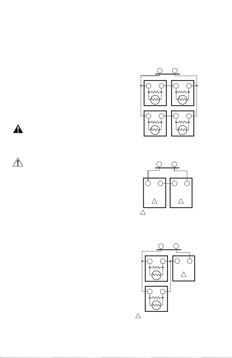
Sensor Wiring for Temperature
Averaging
Fig. 4–Fig. 6 illustrate sensor wiring for temperature
averaging applications.
SUBBASE
Rs Sc
TR21
T T
TR21
T T
Fig. 4. Wiring four TR21 (20K ohm) sensors.
T4 T3
TR21-A
1
THE TR21-A IS A 10K OHM SENSOR.
Fig. 5. Wiring two TR21-A (10K ohm) sensors to
provide a temperature averaging network.
TR21
T
TR21
TT
1
THE TR21-A IS A 10K OHM SENSOR.
Fig. 6. Wiring two TR21 (20K ohm) sensors and
one TR21-A (10K ohm) sensor to provide
a temperature averaging network.
SUBBASE
Rs
SUBBASE
Rs
T
TR21
T T
TR21
T T
M27559
Sc
T4 T3
11
TR21-A
M27560
Sc
T3
T4
1
TR21-A
M27561
62-0311—05 6
 Loading...