

Page 1

Installation and Operations Guide
31-00098-01
TB3026B, TB3026B-W
© Honeywell 31-00098-01
Page 2

Important safety information and installation
!
precautions
Read all instructions
Failure to follow all instructions may result in equipment damage or a hazardous condition. Read all instructions
carefully before installing equipment.
Local codes and practices
Always install equipment in accordance with the National Electric Code and in a manner acceptable to the local
authority having jurisdiction.
Electrostatic sensitivity
This product and its components may be susceptible to electrostatic discharge (ESD). Use appropriate ESD
grounding techniques while handling the product. When possible, always handle the product by its non-electrical
components.
High voltage safety test
Experienced electricians, at first contact, always assume that hazardous voltages may exist in any wiring
system. A safety check using a known, reliable voltage measurement or detection device should be made
immediately before starting work and when work resumes.
Lightning and high-voltage danger
Most electrical injuries involving low-voltage wiring result from sudden, unexpected high voltages on normally
low-voltage wiring. Low-voltage wiring can carry hazardous high voltages under unsafe conditions. Never install
or connect wiring or equipment during electrical storms. Improperly protected wiring can carry a fatal lightning
surge for many miles. All outdoor wiring must be equipped with properly grounded and listed signal circuit
protectors, which must be installed in compliance with local, applicable codes. Never install wiring or equipment
while standing in water.
Wiring and equipment separations
All wiring and controllers must be installed to minimize the possibility of accidental contact with other potentially
hazardous and disruptive power and lighting wiring. Never place 24VAC or communications wiring near other
bare power wires, lightning rods, antennas, transformers, or steam or hot water pipes. Never place wire in any
conduit, box, channel, duct or other enclosure containing power or lighting circuits of any type. Always provide
adequate separation of communications wiring and other electrical wiring according to code. Keep wiring and
controllers at least six feet from large inductive loads (power distribution panels, lighting ballasts, motors, etc.).
Failure to follow these guidelines can introduce electrical interference and cause the system to operate
erratically.
Warning
This equipment has been tested and found to comply with the limits for a class A digital device, pursuant to part
15 of the FCC rules. These limits are designed to provide reasonable protection against harmful interference
when the equipment is operated in a commercial environment. This equipment generates, uses, and can radiate
radio frequency energy and, if not installed and used in accordance with the instruction manual, may cause
harmful interference to radio communications. Operation of this equipment in a residential area is likely to cause
harmful interference, in which case the user will be required to correct the interference at his own expense.
© 2016 Honeywell. All Rights Reserved.
1985 Douglas Drive North
Golden Valley, MN 55422
customer.honeywell.com
By using this Honeywell literature, you agree that Honeywell will have no liability for any damages arising out of
your use, or modification to, the literature. You will defend and indemnify Honeywell, its affiliates and
subsidiaries, from and against any liability, cost, or damages, including attorneys’ fees, arising out of, or resulting
from, any modification to the literature by you.
Questions, corrections, or comments?
To improve our information products and better serve our readers, your feedback is vital. If you have any
questions, corrections, or comments about this publication or any other information products, please send e-mail
to WEBsSquad@honeywell.com.
2
31-00098-01 © Honeywell
Page 3

Contents
Installation and Operations Guide
About the BACnet FF 4
About this document and related publications 5
BACnet FF dimensions 6
Mounting guidelines 7
Installing the wallplate 7
Wiring the wallplate 8
Mounting the BACnet FF faceplate 9
Mounting a door/window sensor 9
Mounting a PIR occupancy motion sensor 11
Terminals and wiring 12
Power supply guidelines and requirements 14
BACnet FF power ratings 14
Selecting a transformer 14
Power supply grounding and wiring 14
Backup power 15
MS/TP LAN Wiring 16
Terminating MS/TP LAN cabling 16
Grounding the MS/TP LAN shield 17
Terminating resistors 17
Configuration 18
Adjusting the date and time 18
Setting the MAC address and device instance 18
Installer setup (ISU) codes 20
Pairing a sensor to a wireless BACnet FF 22
Fixed field service codes 24
Operational overview 25
Configuring a DDCMULTI application 27
Application Sequences and Configuration Settings 28
[AP] 0: Air-to-air heat pump 29
[AP] 1: Water-source heat pump 29
[AP] 2: Air-to-air heat pump 46
[AP] 3: Water source heat pump 46
[AP] 4: Air Conditioning Unit 63
[AP] 5: Air Conditioning Unit 79
[AP] 6: 4 Pipe Fan Coil Unit 96
[AP] 7: 4 Pipe Fan Coil Unit 112
[AP] 8: 4 Pipe Fan Coil Unit 128
[AP] 9: 4 Pipe Fan Coil Unit 146
[AP] 10: Air to Air Heat Pump 164
[AP] 11: 2 Pipe Fan Coil Unit 183
[AP] 12: 2 Pipe Fan Coil Unit 201
[AP] 13: 2 Pipe Fan Coil Unit with Change Over Control 219
[AP] 14: 2 Pipe Fan Coil Unit with Change Over Control 237
[AP] 15: 2 Pipe Fan Coil Unit 255
[AP] 16: 2 Pipe Fan Coil Unit with Change Over Control 272
[AP] 17: 4 Pipe Fan Coil Unit 290
[AP] 18: 2 Pipe Fan Coil Unit with Change Over Control 309
Appendix A: BACnet object and property reference 327
Appendix B: Ordered list of control points 343
Appendix C: Quick reference 347
Appendix D: Canadian conformance statements 348
Contents
|
© Honeywell 31-00098-01 3
Page 4
Installation and Operations Guide
|
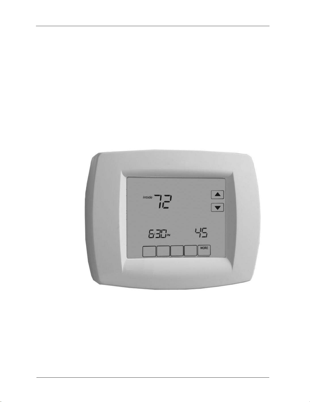
About the BACnet FF
The Honeywell BACnet FF (models TB3026B and TB3026B-W) is a
communicating sensor/fixed application controller with built-in humidity sensor.
The TB3026B-W is the wireless version with an onboard wireless receiver for
wireless occupancy control.
Electrical inputs and outputs wire directly to field equipment. The BACnet FF
comes pre-loaded with nineteen applications that support common uses. These
applications can be selected and some of the parameters adjusted at the
controller without the need for a BACnet front end.
Operational information and control data is available to other building
controllers and systems through the BACnet protocol (ANSI/ASHRAE
standard). This enables a BACnet FF to share data and execute commands
initiated from other BACnet-compliant devices.
BACnet FF
4
31-00098-01 © Ho neywell
Page 5

Installation and Operations Guide
About this document and related publications
|
About this document and related publications
This document provides information about installing and wiring a BACnet FF to
equipment, power, and communication channels. It also shows how to operate
the user interface.
IMPORTANT Always install equipment in accordance with the National
Electric Code and in a manner acceptable to the local authority having
jurisdiction (AHJ). No guidelines, instructions, installation practices, or other
information presented in this guide may be interpreted to supersede or modify
the local codes and practices of the AHJ.
Ta bl e 1 Other documentation related to BACnet FFs
Document (ID) Contains
Installation Instructions (31-00093) Instructions on how to install, wire
and perform initial configuration for
the BACnet FF
Product Data
(31-00096)
WEBs-AX Configuration Wizard Guide
(31-00097)
Summary of capabilities and
specifications
Instructions on how to configure the
BACnet FF through the WEBs based
wizard
© Honeywell 31-00098-01 5
Page 6
Installation and Operations Guide
BACnet FF
|
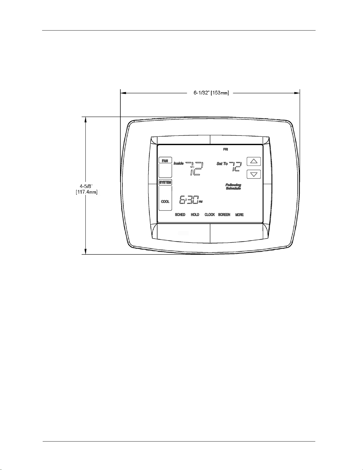
BACnet FF dimensions
The BACnet FF consists of a mounting plate and a circuit board with a plastic
cover. See the BACnet FF Installation Instructions (31-00093) for more
information.
Figure 1 TB3026B and TB3026B-W dimensions
6
31-00098-01 © Ho neywell
Page 7
Mounting guidelines
The BACnet FF is designed to be wall-mounted indoors, with dimensions ideal
for mounting to a single-gang electrical box.
Mount in a clean, dry location away from windows, air ducts, and other places
where environmental factors may affect temperature and humidity readings. If
you mount the BACnet FF on the interior of an outside wall, thoroughly insulate
so outside air behind the sensor does not affect the sensor reading.
To meet requirements of the Americans with Disabilities Act, mount no higher
than 48" from the floor and with a minimum clear floor space of 30" X 48" (760
X 1220 mm).
CAUTION Thoroughly read all instructions before mounting and wiring.
Always install equipment in accordance with applicable electric codes and the
instructions.
Installing the wallplate
The BACnet FF can be mounted horizontally on the wall or on a 4 in. x 2 in.
(101.6 mm x 50.8 mm) wiring box.
Installation and Operations Guide
Mounting guidelines
|
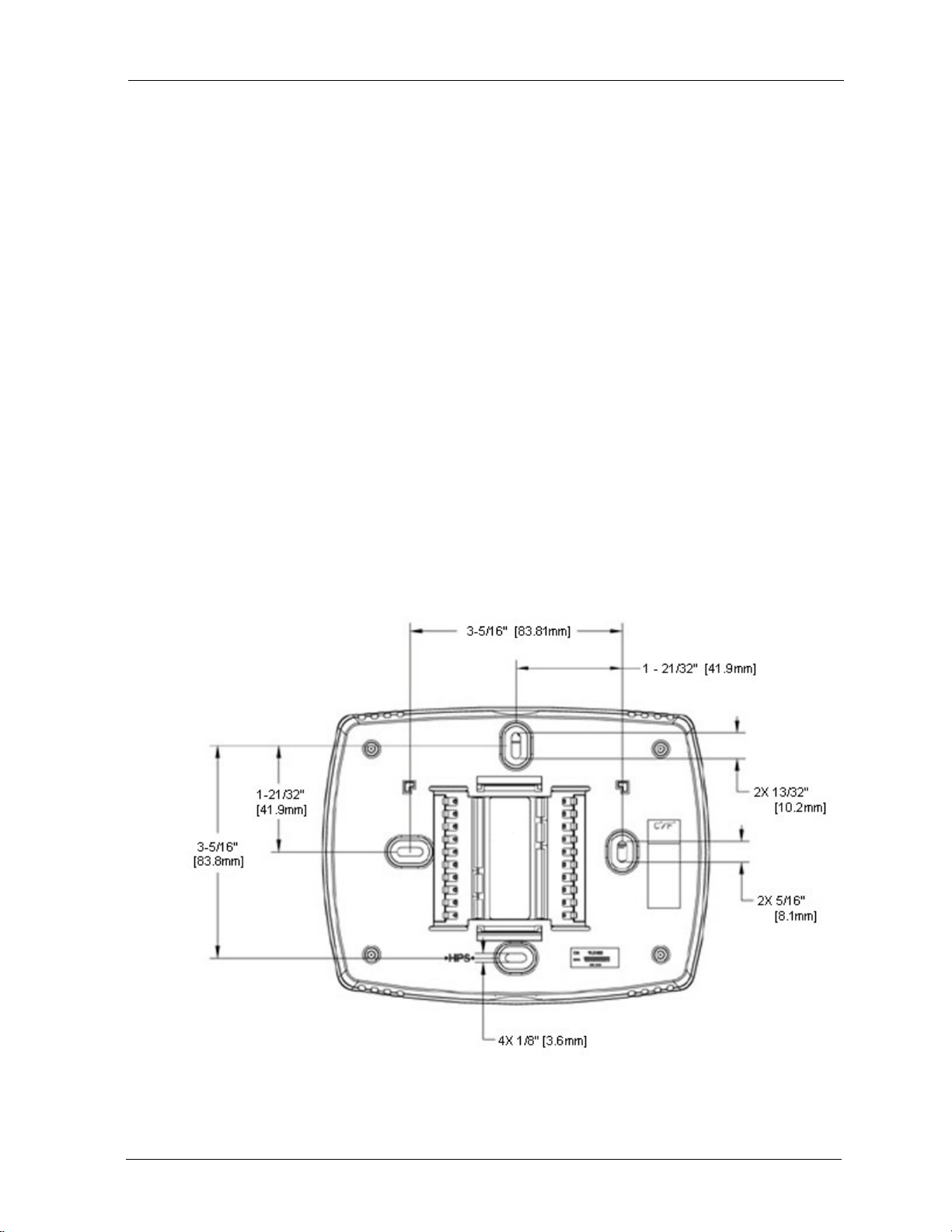
To install the wallplate
1. Position and level the wallplate (for appearance only).
2. Use a pencil to mark the mounting holes.
Figure 2 Wallplate dimensions
3. Remove the wallplate from the wall and, if drywall, drill two 3/16-in.
holes in the wall, as marked. For firmer material such as plaster, drill
© Honeywell 31-00098-01 7
Page 8
Installation and Operations Guide
Wiring the wallplate
CAUTION Disconnect power before wiring. Failure to do so may result in
electrical shock or equipment damage.
BACnet FF
|
two 7/32-in. holes. Gently tap anchors (provided) into the drilled holes
until flush with the wall.
4. Position the wallplate over the holes, pulling wires through the wiring
opening.
5. Insert the mounting screws into the holes and tighten.
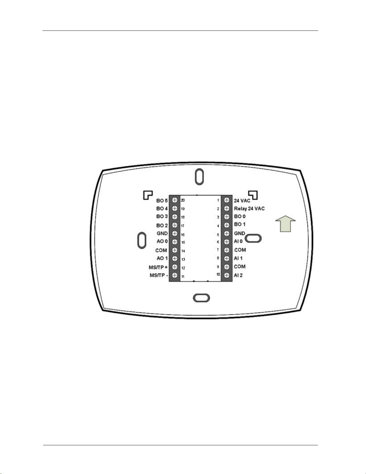
To wire the wallplate
1. Connect wires to the terminal block using Figure 3 as a guide.
Figure 3 Terminal assignments and pin numbers
2. Securely tighten each screw.
3. Push excess wire back into the hole.
4. Plug the hole with nonflammable insulation to prevent drafts from
affecting the BACnet FF.
Note A jumper is pre-installed between pins 1 and 2 (24 VAC and
Relay 24 VAC). This supplies 24 VAC to BO 1, BO 3, and BO 4. It can
be removed if you want to power these inputs from a separate power
supply.
8
31-00098-01 © Ho neywell
Page 9
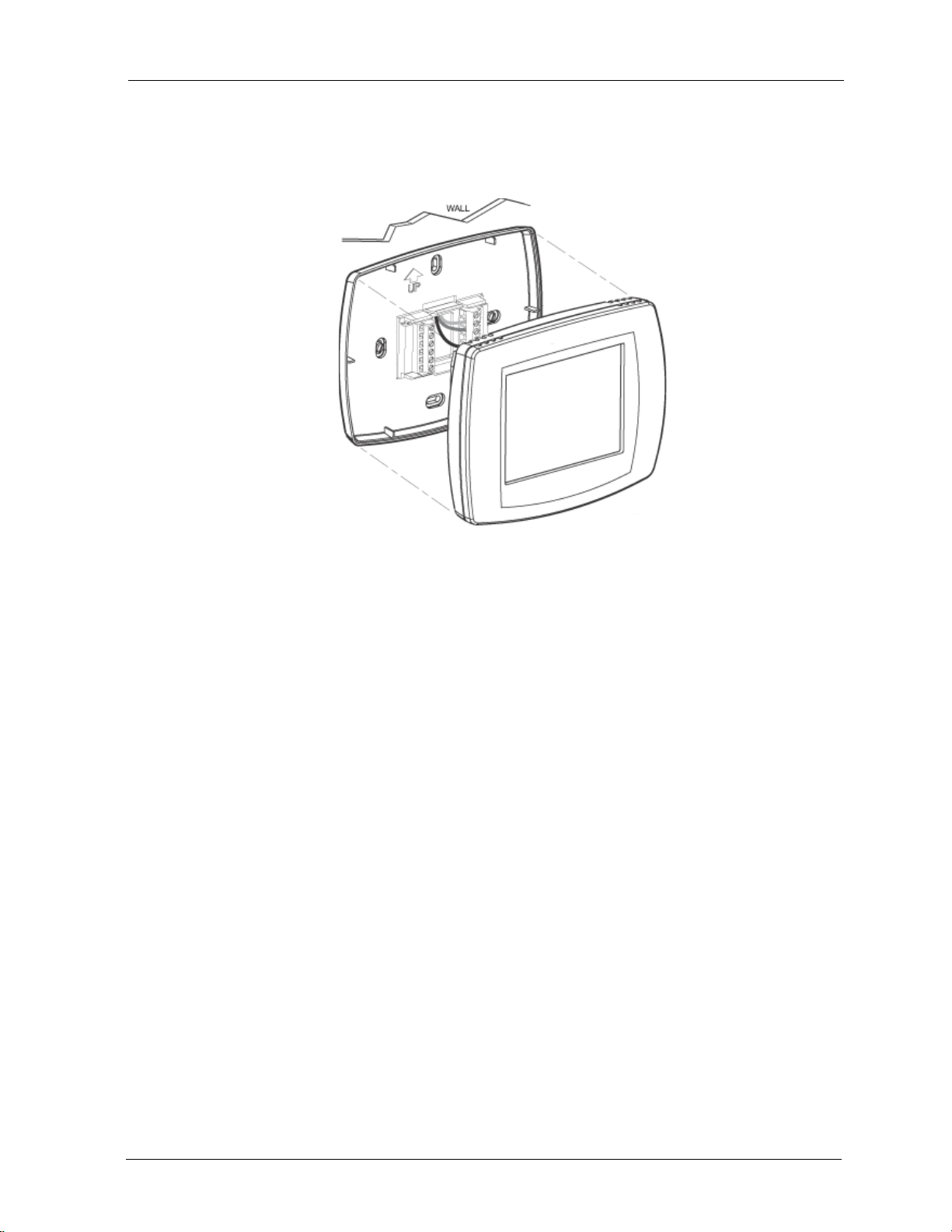
Mounting the BACnet FF faceplate
To mount the BACnet FF faceplate, align the terminal blocks with the pins on
the back of the BACnet FF and push the faceplate straight onto the wallplate.
Installation and Operations Guide
Mounting guidelines
|
Figure 4 BACnet FF faceplate mounting
Mounting a door/window sensor
These instructions apply to the primary door sensor and an optional second
door/window sensor, WSK-24.
Note The BACnet FF supports a maximum of 8 door/window sensors.
To mount a door sensor
1. Remove the battery tab.
Note Completely remove the battery tab or the BACnet FF will not
operate.
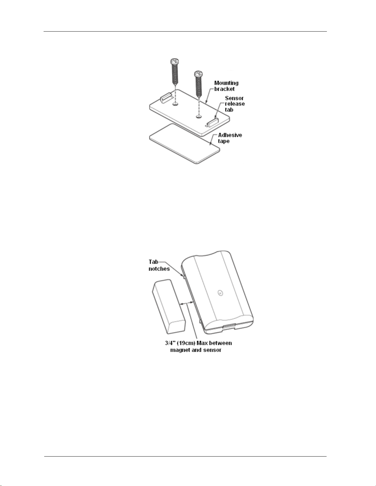
2. Remove the plastic mounting bracket from the door sensor housing.
3. Place the mounting bracket for the door sensor high on the frame of the
door. Secure the bracket to the door frame using the two screws or
adhesive tape provided.
© Honeywell 31-00098-01 9
Page 10
Installation and Operations Guide
BACnet FF
|
4. Door sensor bracket mounting
5. Make sure the notched side of the door sensor is pointing in the
direction that you will mount the magnet.
6. Snap the sensor into the mounting bracket.
7. Align one end of the magnet with the notched side of the door sensor
housing.
8. Mount the magnet a maximum of 3/4 in. (19 mm) from the door sensor.
Figure 5 Maximum distance between door sensor and magnet
9. Secure the magnet to the door by using the two screws or adhesive tape
provided. An optional spacer is provided.
10
10. Open and close the door to ensure that there is no interference.
31-00098-01 © Ho neywell
Page 11
Installation and Operations Guide
Mounting a PIR occupancy motion sensor
Note The BACnet FF supports a maximum of 3 passive infrared (PIR) sensors.
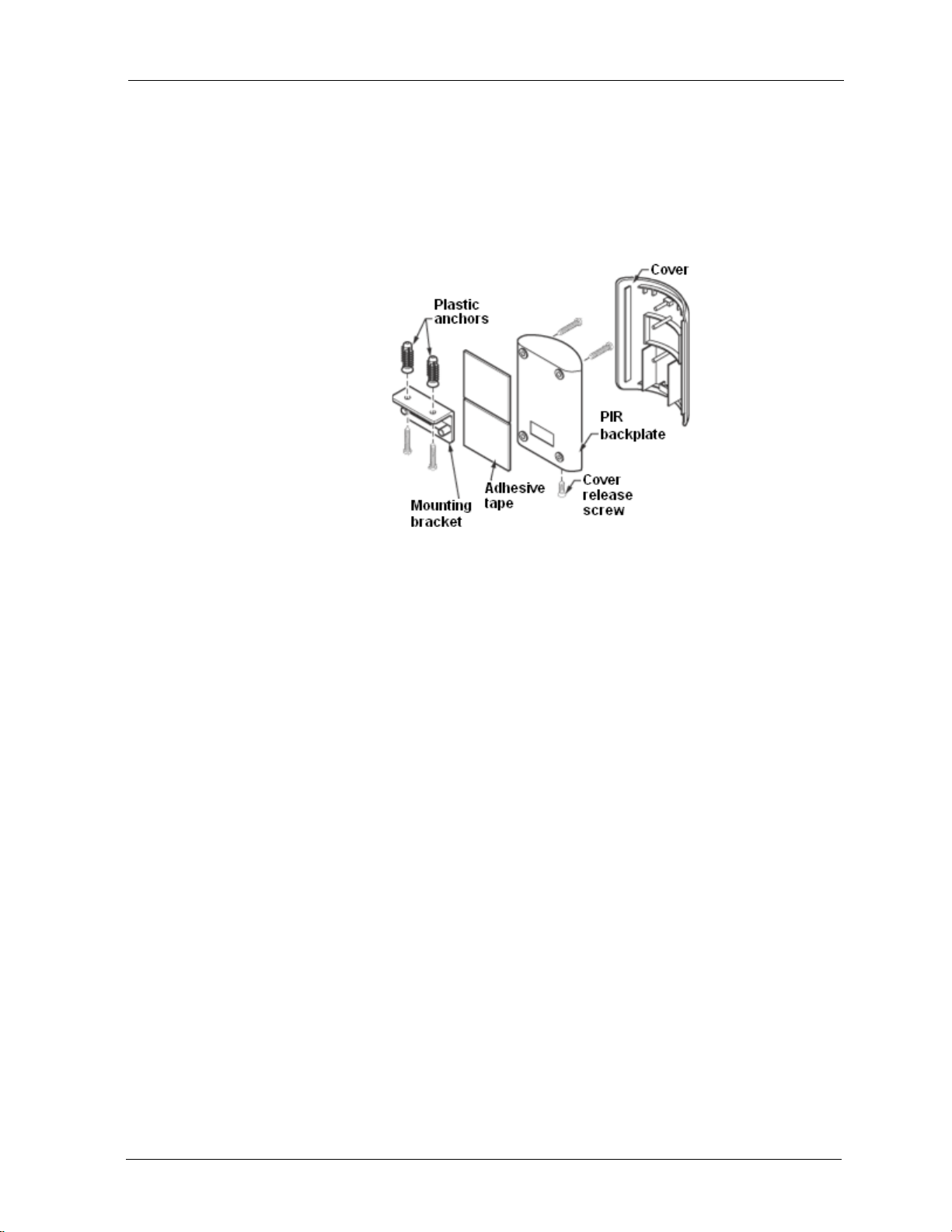
To mount a PIR motion sensor
1. T ake off the cover by removing the cover release screw on the bottom of
the PIR backplate.
Mounting guidelines
|
Figure 6 PIR occupancy motion sensor mounting options
2. Insert three AAA batteries.
3. Secure the PIR sensor to the wall using one of the following options:
• Wall Mount option 1: Use adhesive tape to secure the PIR backplate
to the wall.
• Wall mount option 2: Using either the top or bottom two holes of the
PIR backplate, insert the two long screws to secure the PIR
backplate to the wall.
• Ceiling mount option: Align the m ounting bracket and PIR
backplate. Insert the two small screws into the top holes of the
backplate and secure it to the bracket. Use the two long screws (and,
if necessary, the optional plastic anchors) to mount the bracket and
PIR backplate to the ceiling.
4. Replace the PIR sensor cover and cover release screw.
© Honeywell 31-00098-01 11
Page 12

Installation and Operations Guide
Terminals and wiring
The BACnet FF label identifies wiring terminals by number and function.
T erminals are numbered from top to bottom, beginning with 1 on the upper right
side of the wallplate and continuing top-to-bottom on the right side of the
controller. I/O terminals carry an additional numeric identifier that corresponds
to the software I/O. Use this section to identify terminals on the BACnet FF. See
later sections for more specific instructions, cautions, and recommendations.
Power supply terminals
Use terminals 1 and 5 to connect the 24V AC power supply to the BACnet FF.
Ground terminals
These terminals are used for terminating the grounded leg of the 24VAC circuit
and the return grounds of BOs.
COM terminals
These terminals are used for terminating the return grounds of AIs and AOs.
Universal inputs (AIs)
Use these terminals (in conjunction with adjacent GND terminals) to connect
universal inputs. Input terminals accept a variety of signal types.
BACnet FF
|
Binary outputs (BOs)
Use these terminals to connect BO loads (ON/OFF control). Terminate the BO
return ground to the panel/enclosure ground or a GND terminal on the BACnet
FF.
WARNING! Do not apply line voltage to source pins.
Analog outputs (AOs)
Use these terminals to connect AO-loads (modulating control). The AO-return
ground must terminate to the nearest GND terminal.
MS/TP LAN terminals
Use terminals 11(MS/TP-) and 12 (MS/TP+) to connect the BACnet MS/TP
LAN to the BACnet FF. Maintain polarity throughout the entire LAN. See
“MS/TP LAN Wiring” on page 16 for more information.
12
31-00098-01 © Ho neywell
Page 13

Using terminal blocks
Installation and Operations Guide
The BACnet FF uses header-style termination blocks to simplify field wiring of
power, communications, and I/Os. Terminal blocks accept wire gage from
12–24AWG.
To terminate wire to a BACnet FF
1. Strip approximately 1/8” of the wire jacket from the end of the wire.
2. Use a small screwdriver (1/8” max) to turn the adjustment screw fully
counter-clockwise. The clamps in the wire slot separate as you turn the
screw.
3. Insert the stripped end of the wire into it (try to get the jacket flush with
the terminal block). If using stranded wire, be sure to insert all strands
into the wire slot. If terminating multiple wires, trim wires to same
length and tightly twist exposed wire together.
4. Hold the wire in place and turn the adjustment screw clockwise to
tighten it until the clamps in the wire slot secure the wire.
5. Tug gently on the wire to ensure it is secure.
Terminals and wiring
|
© Honeywell 31-00098-01 13
Page 14
Installation and Operations Guide
BACnet FF
|
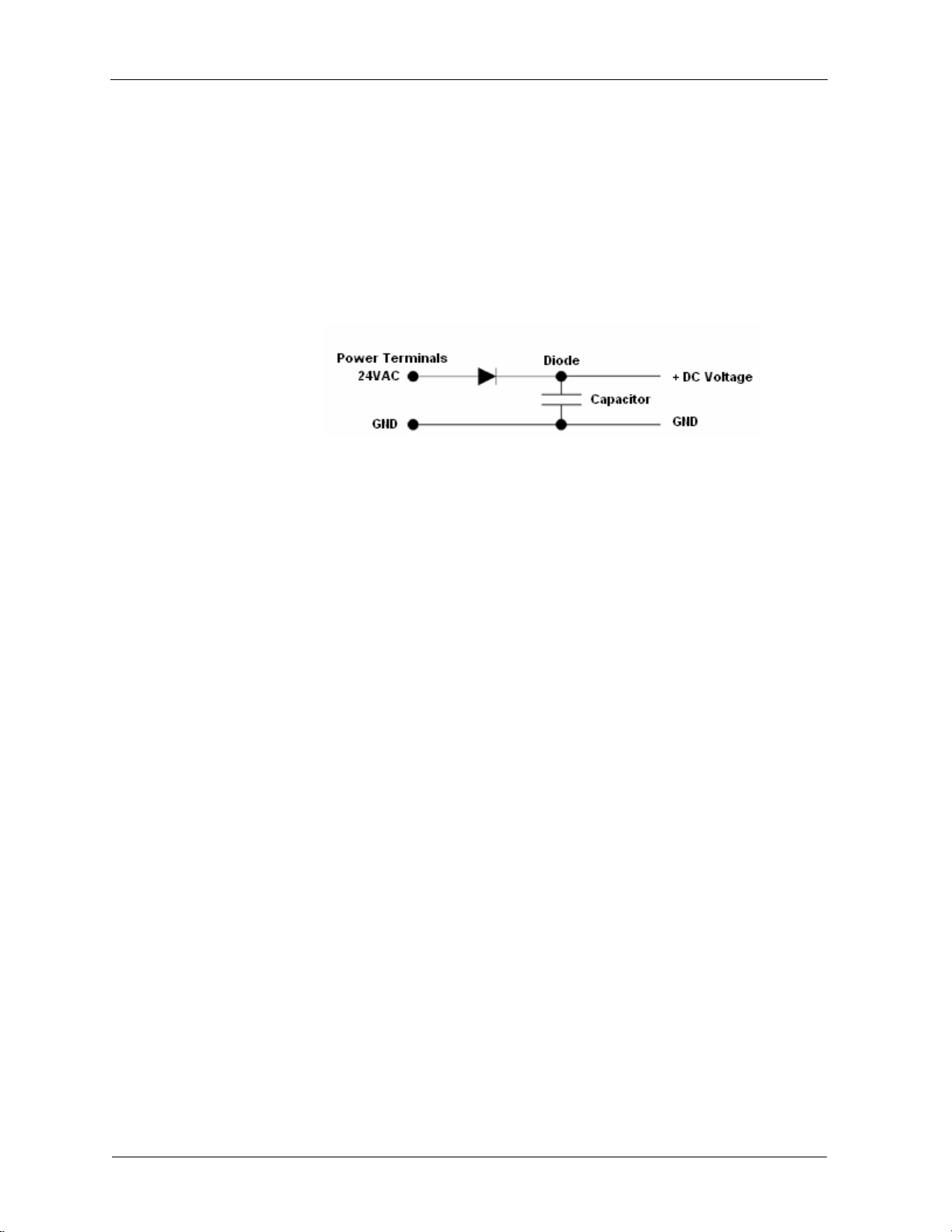
Power supply guidelines and requirements
BACnet FF uses 24VAC power from a UL Listed Class 2 24VAC transformer
(not provided). The BACnet FF uses a half-wave rectifier to convert the AC
power supply to onboard power. This enables multiple BACnet FFs with
half-wave power supplies to be powered from a single, grounded transformer.
CAUTION Half-wave devices and full-wave devices must not use the same AC
transformer. If a BACnet FF will share its power supply with another device,
make sure that the other device utilizes a half-wave rectifier and that polarity of
wiring is maintained. Failure to do so can result in equipm en t dam a ge.
Figure 7 Internal BACnet FF power wiring schematic, half-wave rectifier
BACnet FF power ratings
The BACnet FF minimum current draw is 24 VAC @50ma leading to ~1.2VA.
The minimum applies when the BACnet FF supports no binary output (BO)
loads. If the BACnet FF supports AOs, the minimum VA rating includes the
draw of all AO-loads energized at maximum rating. The maximum power draw
is the minimum VA rating plus the power draw when all BOs are energized at
maximum capacity .
Selecting a transformer
The safest way to size a transformer is to ensure that the maximum VA load
rating of the BACnet FF is less than 85% of the Nameplate VA rating of the
transformer. Even if all outputs are not presently used, this ensures that each
BACnet FF has sufficient power for future equipment additions.
IMPORTANT Transformer sizing should never exceed the maximum UL Class
2 rating.
Power supply grounding and wiring
When connecting power to the BACnet FF, ensure that one leg of the VAC
secondary circuit connects to a known earth ground. Also ensure that the GND
terminal on the BACnet FF connects to the same known earth ground.
Supplying a high-quality ground connection to a BACnet FF and then properly
connecting the BACnet FF to the ground is one of the most important things you
can do to ensure a trouble-free installation.
14
The 24VAC secondary leads are not interchangeable. Once a lead connects to
the GND terminal on the BACnet FF, it is the grounded lead. Observe and
maintain polarity for subsequent connections. The GND terminal provides a
reference ground for the circuit board and communications wiring. Use 18 AWG
cable for best results.
31-00098-01 © Ho neywell
Page 15
Installation and Operations Guide
WARNING Ensure that all BACnet FF power, communications, and I/O
cabling are grounded according to these instructions. Failure to follow these
instructions may result in BACnet FF operational and communication failures or
equipment damage.
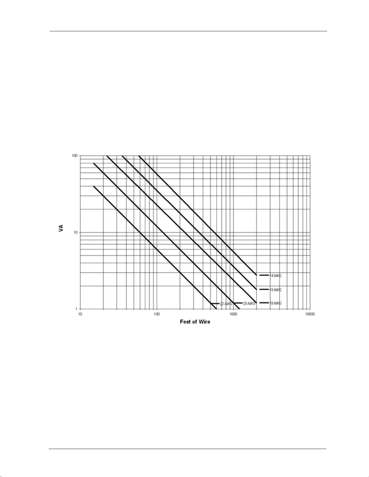
Power supply wire selection
If you are considering long power supply wiring runs, using the right wire size is
critical. If the wire is too small, the resistance may be too high, resulting in a low
voltage supply to the BACnet FF. This is known as line loss. The wire size is
based on the length of the wire run and the current draw of the BACnet FF. Use
Figure 8 to determine wire size; obtain additional information from the
transformer manufacturer.
Power supply guidelines and requirements
|
Figure 8 BACnet FF wiring recommendations
Backup power
The BACnet FF features a built-in supercapacitor that will run the on-board
clock for ten days in the event of power loss.
© Honeywell 31-00098-01 15
Page 16

Installation and Operations Guide
MS/TP LAN Wiring
The BACnet FF communicates on the site-wide BACnet system over a
twisted-pair MS/TP LAN, which uses the EIA–485 signaling standard. BACnet
FFs are master devices on the MS/TP LAN.
BACnet FF
|
Each BACnet FF employs a high-quality EIA–485 transceiver and exerts
load on the MS/TP LAN.
Ta bl e 2 MS/TP LAN facts
Transmission speed 9.6, 19.2, 38.4, 76.8Kbps (configured at global
controller).
Layout Bus.
Cabling BACnet specifies the following. Shielded, twisted-pair
cabling with characteristic impedance between 100 and
130W. Distributed capacitance between conductors
must be less than 30 pF/foot (100 pF/m). Distributed
capacitance between conductor and shield must be less
than 60 pF/foot (200 pF/m). Foil or braided shield
acceptable.
Segment length 4000 ft. (1071 m.) per segment using recommended
wire.
Maximum devices
overall
Depends on classification of devices as master or slave.
Maximum number of master devices is 128. Maximum
number of slave devices or devices overall (mixed
master and slave) is 255. This includes BACnet FFs,
BACnet global controllers (all are considered masters)
and any other devices, regardless of their relative unit
loads.
¼ unit
Maximum devices
per segment
Repeaters Required when making runs longer than 4000 ft. Three
Terminating
resistors
Shield grounding Ground shield drain wire at single point earth (panel)
Terminating MS/TP LAN cabling
MS/TP terminations are located on the lower left of the BACnet FF wallplate.
Maintain polarity of the MS/TP wire run throughout the MS/TP LAN.
Depends on relative unit load of devices (see
“Terminating MS/TP LAN cabling” on page 16).
repeaters maximum between any two devices.
Matched resistors required at each end of segment bus
wired across (+) and (–). Use matched precision
resistors rated ¼W ±1% / 80 - 130 Ohms.
ground, not BACnet FF ground. Tape off shield drain
wire at other end. Tie shield drain wire through at each
BACnet FF.
16
31-00098-01 © Ho neywell
Page 17

Grounding the MS/TP LAN shield
Proper shield grounding of the MS/TP cabling can help minimize the risk of
communications problems and damage to equipment because of transient
voltage spikes (for example, lightning strikes).
Follow these guidelines for grounding MS/TP cable shields:
• Each MS/TP segment should have a single point of shield ground,
preferably as close to the middle of the cabling run as possible.
• Do not ground the MS/TP shield using a BACnet FF terminal.
• Never ground both ends of a shield; differences in potential between the
grounds may induce current on the shield, causing interference.
• At termination conn ectin g points, tie the shield through with a wire nut.
• At ungrounded, exposed shield points (the end of a segment), tape back
the shield to the wire jacket or, for optimum transient shunting, use
100V gas discharge tubes or 120V MOVs between shield and ground.
Terminating resistors
Matched terminating resistors wired across MS/TP+ and MS/TP– are required at
the last device on each end of the MS/TP segment for signal integrity (Figure 9).
Installation and Operations Guide
MS/TP LAN Wiring
|
Optimum segment performance typically requires “tuning,” a process by which
the value of the terminating resistors is selected based on the wave form of
signals on the segment. View wave forms using an industrial scope meter. The
goal is to have as square a wave form as possible with an amplitude greater than
200 mV. Resistors affect the wave form as follows:
• When the resistance value decreases, the amplitude of the wave form
decreases and becomes more square.
• When the resistance value increases, the amplitude of the wave form
increases and becomes less square.
Typically, precision resistors in the range 80-130 Ohms (+
results. Ideally, the value of the terminating resistors should match the rated
characteristic impedance of the installed cable. For example, if the installed
MS/TP cable has a listed characteristic impedance of 100 Ohm, install 100 Ohm
matched precision resistors.
CAUTION Do not mismatch terminating r e sistors. Ensure that both resistors
on a segment have the same value.
Note Typically, White is Data - and Black is Data +.
1%) yield acceptable
Figure 9 Terminating resistor detail
© Honeywell 31-00098-01 17
Page 18

Installation and Operations Guide
BACnet FF
|
Configuration
Once the BACnet FF is mounted and wired, configure it from the BACnet FF
touchscreen.
Adjusting the date and time
When the controller is first powered up, you may need to set the date and time.
These are set at the factory, but the on-board power supply may have run down.
If this happens, adjust the date and time.
To adjust the time
1. Touch Clock at the bottom of the screen.
1. Use the arrows to adjust the year, month, and day.
2. Press DONE.
3. Adjust the time and press DONE.
T o manually adju st the date and ti me after initial setup, see “Clock operation” on
page 25.
Setting the MAC address and device instance
The factory default MAC address is 0. Valid MAC addresses are 0-127. The
default device instance is 0009999. Valid device instances are 0-4194302.
Note The device instance can also be set using a BACnet Supervisor
To set the MAC address and device instance at the display
1. From the home screen, press SYSTEM (left side of the screen).
Five blank touch keys will appear at the bottom of the screen.
18
31-00098-01 © Ho neywell
Page 19
Installation and Operations Guide
E
CANC
MO
USASU
SYSTE
OFF
g
Schedule
de
Se
o
M19923
Configuration
|
2. Press and hold the two blank keys on either side of the center key for
approximately five seconds (see Figure 10).
T
Insi
DON
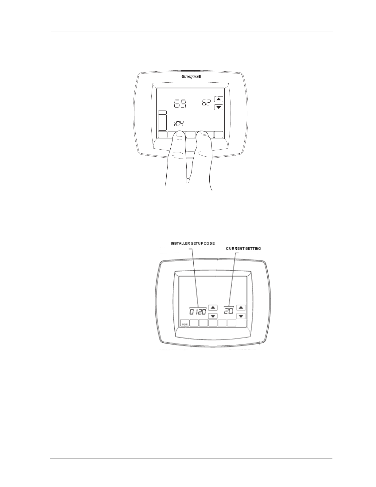
Figure 10 Entering ISU mode
t T
Followin
The installer setup (ISU) screen appears. An ISU code is displayed in
the lower left. It is a four-digit code beginning with zero. The current
setting is displayed in the lower right.
Figure 11 ISU screen
3. Use the down arrow next to the installer setup code to advance to ISU
code 800.
4. Use the up and down arrows next to the current setting to set ISU code
800 (MAC address) to a value between 0 and 127.
5. Set ISU code 801 (first digit of device instance) to a value between 0
and 4.
Note The device instance is set by entering values in four separate
ISU codes. See example on page 20.
© Honeywell 31-00098-01 19
Page 20

Installation and Operations Guide
BACnet FF
|
6. Set ISU code 802 (second and third digits of device instance) to a value
7. Set ISU code 803 (fourth and fifth digits of device instance) to a value
8. Set ISU code 804 (sixth and seventh digits of device instance) to a value
9. Press Done to exit installer setup.
Installer setup (ISU) codes
Installer setup mode provides access to functions specific to installation of a
BACnet FF. Some BACnet FF configuration parameters can be altered from the
ISU screens. The ISU parameters can also be accessed via BACnet.
between 00 and 99.
between 00 and 99.
between 0 and 99.
For example, if you want to set the MAC address to 15 and the device
instance to 1876, you would use these settings:
ISU code 800=15
ISU code 801=0
ISU code 802=00
ISU code 803=18
ISU code 804=76
You can require a PIN to access ISU mode by setting AV-133 to a non-zero,
four-digit number.
To access the ISU screens
1. From the home screen, press SYSTEM (left side of the screen).
2. Five blank touch keys appear on the bottom of the screen between the
Done and Cancel keys. Press and hold the two blank keys on either side
of the center key for approximately five seconds. See Figure 10.
3. If a PIN code is required, use the top arrows to select the first two digits
of the code and the bottom arrows to select the third and fourth digits of
the code, and then press DONE.
The ISU screen appears.
4. Use the arrows to select parameters and values. See Table 3 for details.
5. Press DONE.
20
31-00098-01 © Ho neywell
Page 21

Installation and Operations Guide
Note After five minut es of inacti vit y, the ISU screen reverts to the
main screen.
Table 3 provides a list of ISU param e ters
Ta bl e 3 ISU parameters
ISU
Parameter
Code
Description Allowed Values
120 Year, first 2 digits 19-21
Configuration
|
130 Year, second 2
00-99 (00-54 if ISU 200=21)
digits
140 Month 1-12
150 Day 1-31
160 Schedule format
BV-133
280 Backlight control
BV-79
320 Swap
English/Metric
0 – not programmable (BV-133=0) 4 – 7
day programmable (BV-133=1)
0 – on for 20 seconds after keypress
1 – low always on, bright after keypress
1 – show opposite units to specified in
DDC header
BV-69
330 Daylight saving
AV-127
500 Filter change
reminder
AV-124
0 – off; no automatic adjustments
1 – pre 2007 scheme
2 – 2007 and later scheme
0 – reminder not used
1 – 10 days
2 – 30 days
3 – 60 days
4 – 90 days
5 – 120 days
6 – 365 days
510 Hum pad change
reminder
AV-125
520 UV lamp change
reminder
0 – reminder not used
1 – 90 days
2 – 180 days
3 – 365 days
0 – reminder not used
1 – 365 days
AV-126
540 Program periods
AV-129
640 Clock format
BV-83
670 Keypad lock
AV-128
© Honeywell 31-00098-01 21
2 – Wake/Sleep
4 – Wake/Leave/Return/Sleep
12 – 12 hour (BV-83=0)
24 – 24 hour (BV-83=1)
0 – no lock
1 – access temperature settings only
2 – fully locked
Page 22

Installation and Operations Guide
Ta bl e 3 ISU parameters
BACnet FF
|
ISU
Parameter
Code
Description Allowed Values
700 Sensed room
temperature offset
(AV-138)
701 Sensed room
humidity offset
(AV-139)
702 Sensed outside air
temperature offset
(AV-140)
703 Sensed outside
humidity offset
(AV-141)
800 MS/TP MAC 0-127
801 BACnet Device
Instance - first digit
802 BACnet Device
Instance second and
third digits
803 BACnet Device
Instance forth and
fifth digits
-4 to +4 degrees F
-5% TO +5%
Humidity cannot be adjusted above
100% or below 0%.
-4 to +4 degrees F
-5% TO +5%
Humidity cannot be adjusted above
100% or below 0%.
0-4
00-99
00-99
804 BACnet Device
Instance sixth and
seventh digits
Pairing a sensor to a wireless BACnet FF
The BACnet FF and wireless sensor kits (WSK-24) ship unpaired, verified by
two dashes in the Sensor Status field on the BACnet FF’s Wireless Sensor Setup
screen. To pair them, issue a pairing command from the BACnet FF and then
activate the sensor.
Accessed from Field Service Mode, the BACnet FF’s W i reless Sensor Setup
Mode includes diagnostic screens for configuration and checkout of associated
sensors. With :UC displayed in Field Service Mode, press the blank key (blank
area) just to the left of the blank center key, and then press the down arrow key
next to the :UC parameter.
Door/window sensors may be paired to any available sensor number in the range
1-8. When cycling through sensor numbers on the Wireless Sensor Setup screen,
unpaired sensor numbers show a status of --.
PIR sensors may be paired to any available sensor number in the range 1-3.
00-99
22
31-00098-01 © Ho neywell
Page 23
Installation and Operations Guide
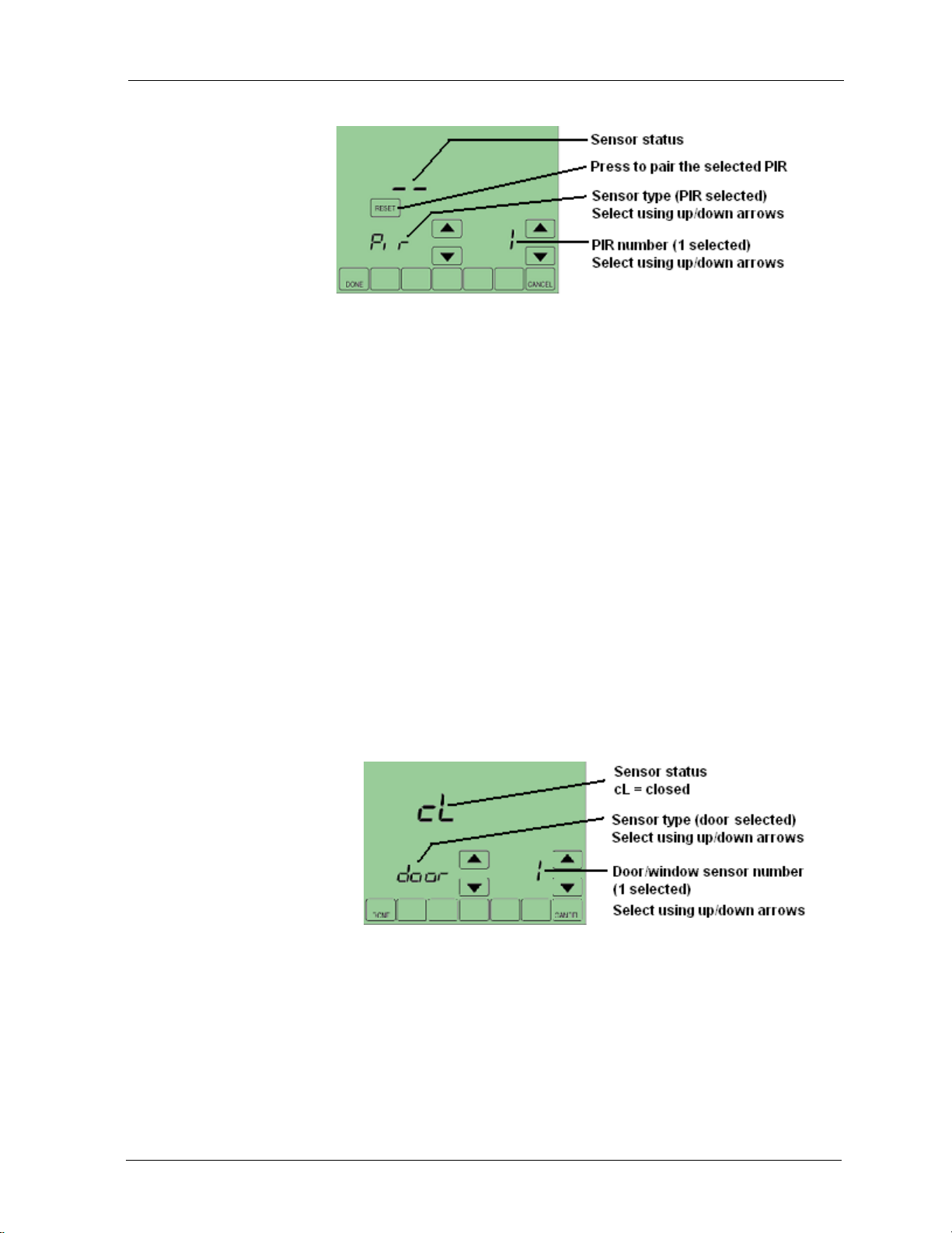
Figure 12 Wireless Sensor Setup screen
To pair a sensor to a BACnet FF
1. Make sure the battery is installed and activated in the sensor.
2. If the sensor is a door/window switch, align the magnet so that the
sensor is in the closed position. If the sensor is a PIR sensor, cover the
PIR.
IMPORTANT! Verify that the sliding door/window contact is closed
and cover all other PIRs to prevent interference during the pairing
process.
|
Configuration
3. On the BACnet FF select the sensor to pair and then press Reset.
The RESET key disappears and WAIT is displayed indicating that the
BACnet FF is waiting to pair the sensor with the next device that
receives a radio signal.
4. Activate the sensor you want to pair.
Note Pairing times out after 10 seconds of no pairing activity.
5. Verify that the BACnet FF and sensor successfully paired.
Paired = sensor status is displayed, replacing --.
Timed out = RESET is displayed and sensor status
is --.
Figure 13 Door sensor number 1 paired and in closed status.
To erase sensor-to-BACnet FF pairings
1. While viewing any sensor status screen while pairing is not taking
place, press the blank key to the left of CANCEL.
2. Press the blank key to the right of DONE.
The sensor status field displays --, indicating unpaired.
© Honeywell 31-00098-01 23
Page 24

Installation and Operations Guide
Fixed field service codes
Field service mode enables technicians to query and command key operating
variables in the BACnet FF while at the BACnet FF touchscreen. A technician
presses a particular key sequence at the BACnet FF to enter field service mode.
In field service mode a technician uses the left arrows to scroll through data
codes and the right arrows to change the value associated with a code.
The lower left of the LCD shows the two-digit data code and the main area
displays the data value. A pre-defined list of data codes is available within the
description of each application. See Ta ble 8 as an example for applications 0 and
1. “Configuring a DDCMULTI application” on page 27 provides mo re
information about these settings.
Note When using the local user interface to change applications (AV-49), the
application defaults will NOT change and must be changed manually.
You can deny users access to field service mode by setting BV-68 to ON. You
can also require a PIN code in order to enter field service mode by setting
AV-132 to the desired PIN number.
Field service mode ends automatically if there is no key activity for five minutes.
BACnet FF
|
Setting field service codes
To set field service codes
1. From the home screen, press SYSTEM (left side of the screen).
2. Press and hold the center bottom key (blank) for about five seconds. See
Figure 10.
3. If a PIN code is required, use the top arrows to select the first two digits
of the code and the bottom arrows to select the third and fourth digits of
the code, and then press DONE.
The field service screen appears.
4. Press the left up or down arrows until the desired code appears. See
T able 8 on page 42 for the list of Setup Codes. NOTE: All applications
use the same Setup Codes.
5. Press the right up or down arrows to adjust the value associated with the
code.
6. Press the left up or down arrows to accept the change and scroll to a
different code.
7. Press DONE to exit field service mode.
24
31-00098-01 © Ho neywell
Page 25

Operational overview
The BACnet FF operates in one of three modes - Setpoint, Occupancy Single
Setpoint, and Occupancy Dual Setpoint.
Common features
This section describes features common to all operating modes. For descriptions
of mode-specific features, see “Checking MS/TP communication” on page 26
and “Checking MS/TP communication” on page 26.
LCD backlight operation
BV-79 controls backlight operation. If BV-79 is OFF, the backlight turns ON
when any key is pressed and stays on for 20 seconds after there is no key activity.
If BV-79 is ON, the backlight is ON continuously.
Clock operation
The BACnet FF’s real-time clock provides time and date for displaying the date
and time, implementing daylight savings settings, and implementing schedules.
If AC power is lost, a supercapacitor will power the clock for ten days. If the
date and time are lost, the BACnet FF will display the set time and date screens
when powered up.
Installation and Operations Guide
Operational overview
|
Note The real-time clock is separate from the CPU time keeping utility. It only
affects the items listed in this section.
Daylight savings (DLS) settings can be controlled by a BACnet FF or by a
BACnet Supervisor. If installer setup (ISU) parameter 330 is set to non-zero, the
BACnet FF will control DLS settings. If ISU 330 is zero, DLS is controlled by a
BACnet Supervisor.
The clock accepts time syncs from a BACnet Supervisor. If configured in DDC,
the date and time can also be set manually using the display. To den y a user
permission to set the clock, set BV-116 to 1.
The last time command, whether from the user screen or BACnet, takes
precedence.
To adjust the real-time clock
1. Press CLOCK.
2. Use the arrow keys to select a year, month, and day.
3. Press DONE.
4. Select a time.
5. Press DONE.
© Honeywell 31-00098-01 25
Page 26
Installation and Operations Guide
Baud rate
Requests seen
Headers seen
MAC address
BACnet FF
|
MORE key navigation
The MORE key allows a programmer to make additional screens available to
users. Enabling the display of one or more of these screens causes the MORE
key to appear on the main screen. The screens that can be made available are:
• Outside air temperature
• Inside/outside humidity
When the user presses MORE, the first enabled screen appears. Pressing
MORE again displays the next screen.
Touchscreen cleaning
If the display screen needs to be cleaned, the user presses SCREEN. The display
will lock for 30 seconds allowing the user to wipe the screen without pressing
any keys. When the display reads 0, press SCREEN to continue cleaning or
DONE to quit. Use a non-abrasive glass cleaner.
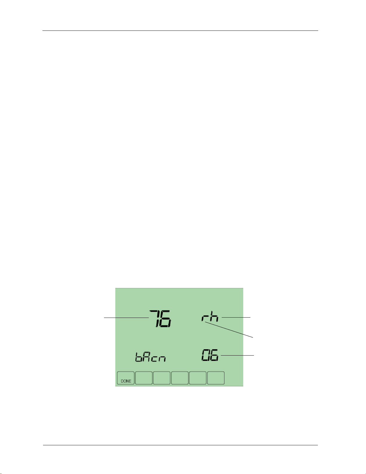
Checking MS/TP communication
You can check MS/TP communication from the display. The BACnet FF will
indicate if MS/TP packets and headers have been seen, the baud rate, and the
MAC address.
To check MS/TP communication
1. Enter field service mode. See “To set field service codes” on page 24.
2. Ensure the UC code is displayed.
3. Press the blank key usually labeled MORE (bottom row, second from
right).
4. Press the down arrow near the UC code.
The MS/TP communication screen appears.
26
5. Press DONE twice to exit.
31-00098-01 © Ho neywell
Page 27

Installation and Operations Guide
Configuring a DDCMULTI application
The BACnet FF is pre-loaded with DDC that lets you select one of multiple
applications. Applications for heat pumps, A/C units, and fan coil units are all
contained in the same DDC file. Using one of these applications, an installer can
configure the controller in the field - just set the MS/TP parameters, device
instance, and application [AP] (AV-49) parameters and it is ready to go.
Note When using the local user interface to change applications (AV-49), the
application defaults will NOT change and must be changed manually. However,
The Niagara-based configuration wizard will change the application specific
default values.
Advanced application settings will require a BACnet connection to a BACnet
BMS. These detailed application settings need to be reviewed to ensure all are
set correctly before enabling the device's outputs.
CAUTION Setting the [OE] field service code to ON powers up the outputs.
Ensure that the outputs are configured correctly before setting OE to ON.Failure
to do so may result in equipment damage.
1. Set field service code [OE] (BV-2) to ON to power up the outputs.
Configuring a DDCMULTI application
|
2. Press DONE.
© Honeywell 31-00098-01 27
Page 28

Installation and Operations Guide
BACnet FF
|
Application Sequences and Configuration Settings
Table 4 shows settings for all 19 applications and should be referenced
accordingly
Ta bl e 4 Primary settings for the 19 apps
Code Point Value Default Options Units Notes
160 BV-133 Internal Sched
Enable
280 BV-79 Backlight ON Inactive
320 BV-69 Swap Eng -
Don't use this is
on custom
screen
330 AV-127 Day Light
Savings Option
500 AV-124 Filter Period 0 0
510 AV-125 Pad Period 0 0
Inactive Inactive/Active
2 0-2 0 - disable, 1 - pre 2007, 2 -
2007+
520 AV-126 UV Period 0 0
540 AV-129 Prog Periods 0 0
640 BV-83 Clock Fmt
Inactive 12 hr
Active 24 hr
670 AV-128 Keypad Lock
0-no lock,
1-temp settings
only, 2-locked
700 AV-138 Temp Offset 0 0
701 AV-139 Humidity Offset 0 0
702 AV-140 OA Temp Offset 0 0
703 AV-141 Humidity Offset 0 0
BV-141 Deny Schedule
Edits
BV-114 Deny Schedule
View
BV-115 Deny
Permanent Hold
BV-130 Deny Vacation
Hold
Inactive Inactive/Active
Inactive Inactive/Active
Inactive Inactive/Active
Inactive Inactive/Active
28
BV-116 Deny Clock
Adjust
AV-132 FS PIN 0 0 Pin locks field service
AV-133 ISU PIN 0 0 Pin locks ISU service access
Inactive Inactive/Active
access
31-00098-01 © Ho neywell
Page 29

Installation and Operations Guide
Heat Pumps: Apps 0 and 1 [AP] 0: Air-to-air heat pump and [AP] 1:
|
Heat Pumps: Apps 0 and 1
[AP] 0: Air-to-air heat pump and
[AP] 1: Water-source heat pump
Single-speed fan with binary output start/stop. optional analog variable-speed
fan control, 1-stage auxiliary heat, optional floating or analog economizer.
Fan mode control (AV-17)
• 1 = continuous
• 2 = cycle with heating
• 3 = cycle with heating/cooling
Configurable Occupancy Modes
• SYSTEM Block: AUTO/OFF selection (Occupied/Unoccupied)
• Occupancy mode (AV-123=0, default): Schedules Occupancy states
Inputs and Outputs
• Setpoint mode (AV-123=1): Schedules Setpoints
• Dual setpoint mode (AV-123=2): Dual setpoints when Occupied
• Internal schedules enabled when BV-133 is active or ISU 160=4
• BMS schedules enabled when BV-56 is active
Ta bl e 5 Inputs and Outputs: [AP] 0 and [AP] 1
Point Function
AI-0 Optional:
Use as space sensor in place of the internal space
sensor AV-104 (Set BV-32 active and BV-47 inactive)
Use as an outdoor-air sensor; maps to display
AV-103 (Set BV-47 active and BV-32 inactive)
BI-1 Optional standby input (for PIR/door/window sensor)
AI-2 Supply-air sensor (optional, but required for
economizer option)
BI-2 Normally-open condensate sensor (optional)
BO-0 Fan
BO-1 Heat-pump compressor
BO-2 Reversing valve
BO-3 Heating stage 1 (optional)
© Honeywell 31-00098-01 29
Page 30
Installation and Operations Guide
Fan
HP Cmpr
Rev Vlv
Htg Stg 1
Econ Opn
Econ
Econ Cls
Controller Terminations
HPH1 AP 0
GND
5
BO 0
BO 1
BO 2
BO 3
BO 4
BO 5
AO 1
G
Y1
O/B
W1
EC
EC
EC
0-10Vdc
Com
14
AO 0
C
RC24VAC
1
24V
Com
BI/AI 1
COM
BI/AI 2
COM
BI/AI 0
Sensor *
SA Sensor
Optional
Standby
N.C. or N.O.
Optional
Condensate
alarm or fail
VC
VFD /SCR
4-20ma
* Optional space or outside temperature sensor.
4-20ma
Ta bl e 5 Inputs and Outputs: [AP] 0 and [AP] 1
Point Function
BO-4 Economizer open (optional)
BO-5 Economizer close (optional)
AO-0 Economizer (optional)
AO-1 Analog fan speed (optional)
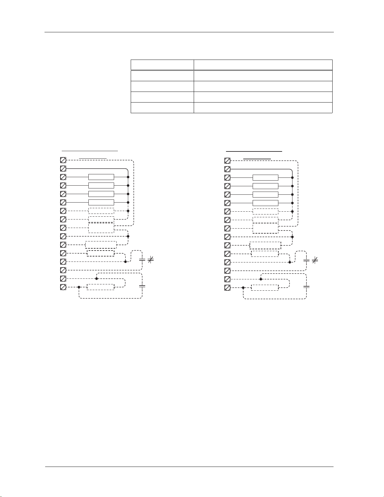
Wiring diagrams
BACnet FF
|
Controller Terminations
RC24VAC
C
G
Y1
O/B
W1
EC
EC
EC
VC
0-10Vdc
4-20ma
4-20ma
HPH1 AP 1
HP Cmpr
Rev Vlv
Htg Stg 1
Econ Opn
Econ Cls
Econ
VFD /SCR
Sensor *
SA Sensor
GND
BO 0
BO 1
BO 2
BO 3
BO 4
BO 5
AO 0
Com
14
AO 1
BI/AI 0
COM
BI/AI 1
COM
BI/AI 2
1
5
Fan
24V
Com
Optional
Standby
N.C. or N.O.
Optional
Condensate
alarm or fail
Figure 14 Controller terminations: [AP] 0, [AP] 1
Sequences of Operation
SYSTEM Block Control (BV-102)
30
* Optional space or outside temperature sensor.
Controller outputs are disabled when Enable Outputs [OE] BV-2 OF/On is in the
OF (inactive) state. Do not enable outputs until you are certain the wiring and
configuration is correct and complete.
When the unit is configured to run in Occupancy Mode, the SYSTEM Block
allows the user direct control of occupied or unoccupied state from the controller
display. Selecting “Auto” places the controller in Occupied state. Selecting
“OFF” places the controller in unoccupied state.
The SYSTEM Block can be hidden by setting BV-102 inactive. When the
SYSTEM Block is hidden occupancy states are controlled exclusively by the
onboard or BMS schedules.
31-00098-01 © Ho neywell
Page 31

Installation and Operations Guide
If onboard or BMS schedules are enabled, the “OFF” selection will override the
controller’s scheduled state and force the unit into Unoccupied state. If you do
not want the user to have this ability, set BV-102 inactive to hide the SYSTEM
Block.
You can optionally change the behavior of the SYSTEM Block “OFF” setting so
that instead of placing the controller in the Unoccupied state, the controller will
turn the fan off. Heating and cooling are disabled when the fan is off. The fan
will remain off until the user changes the SYSTEM Block to “Auto.” Set BV-10
to active to allow this option.
Heat Pumps: Apps 0 and 1 [AP] 0: Air-to-air heat pump and [AP] 1:
|
Figure 15 Display: SYSTEM Block OFF; SYSTEM Block AUTO
Configure schedules
The BACnet FF can be configured to follow an internal schedule by setting ISU
parameter 160 or BV -133. The BACnet FF may also be scheduled by a BMS. Set
BV-56 to active to enable BMS schedules. BV-133 changes to inactive when
BV-56 is active.
If the internal schedule is OFF, the user can adjust the setpoint (within setpoint
limits).
Schedules are stored in flash memory so they persist through power cycles.
Occupancy control (AV-123 = 0, default)
The controller operates in Occupied state when the Occupied Command (BV -64)
is turned ON by any of the following:
• When the controller’s SYSTEM Block “AUTO” is selected by the user
• By local internal schedule, which writes to BV-40 at priority 16
• By a command sent from a BMS schedule or BMS operator override,
writing to BV-40.
Note If the user is allowed to command the SYSTEM Block, this
command is at priority 10. BMS schedules should write to one of the
BV-40 priorities 12-16 to avoid overriding the user command.
• When the occupant has initiated an aft er-hours override by pressing the
override arrows on the touch screen.
The Unoccupied Setpoints are activated when the controller’s SYSTEM Block is
set to “OFF” by the user.
© Honeywell 31-00098-01 31
Page 32

Installation and Operations Guide
When operating in the Unoccupied state, the override up/down arrows can be
pressed to force the controller into the Occupied state for up to 4 hours (default
value). The override time limit (AV-97) is adjustable from a minimum of 0.2
hours to a maximum of 9.5 hours.
Setting BV-9 to active enables the controller to default to Occupied state
whenever communication with the BMS is lost continuously for more than 5
minutes. The command to Occupied state is implemented by setting BV-64 to
active.
Occupied, Unoccupied, and Standby Heating and Cooling
Setpoints
When operating in the Unoccupied state, the cooling and heating setpoint revert
to specific values:
When operating in the Occupied state, the cooling and heating setpoints are
calculated as offsets from the user adjustable Space Setpoint (AV-90):
BACnet FF
|
• Current Cooling Setpoi nt (AV-99) = Unoccupied Cooling Setpoint
(AV-95)
• Current Heating Setpoint (AV-100) = Unoccupied Heating Setpoint
(AV-96)
• Current Cooling Setpoint (AV-99) = AV-90 plus AV-93 plus Demand
Offset (AV-106)
• Current Heating Setpoint (AV-100) = AV-90 minus AV-94 minus
Demand Offset (AV-106)
When operating in the Standby mode, the Current Cooling Setpoint and Current
Heating Setpoint are calculated as for occupied mode as described above.
However the standby offset ([SO]:, AV-19) is transferred to the Demand Offset
(AV-106) before the computations, resulting in relaxed setpoints during standby
operation.
User adjustment of the Space Setpoint (AV-90) value is limited by the Setpoint
High Limit (AV-91) and the Setpoint Low Limit (AV-92).
Ta bl e 6 Setpoint values in Occupancy control
Field Code De scription
[:SP] AV-90 Space Setpoint
[:HI] AV-91 Setpoint High Limit
[:LO] AV-92 Setpoint Low Limit
[:CO] AV-93 Cooling Setpoint Offset
32
[:HO] AV-94 Heating Setpoint Offset
[:UC] AV-95 Un occupied Cooling Setpoint
[:UH] AV-96Unoccupied Heating Setpoint
31-00098-01 © Ho neywell
Page 33

Installation and Operations Guide
Ta bl e 6 Setpoint values in Occupancy control
Field Code De scription
[CS] AV-99 current calculated Cooling Setpoint
[HS] AV-100 current calculated Heating Setpoint
-- AV-106 demand offset (AV-106 value updates AV-99, AV-100)
[SO] AV-19 standby offset; 0 minimum, 6 maximum degrees DDC transfers value to
AV-106
Setpoint control (AV-123 = 1)
In setpoint mode, the controller logically emulates residential thermostats. The
space temperature is controlled to "SP Mode Cooling SP" (AV-108) and "SP
Mode Heating SP" (AV-109). These setpoints are writable using BACnet. Each
schedule period consists of a start time, a heating setpoint, and a cooling
setpoint. The maximum number of periods per day is configured using ISU
parameter 540 (AV-129). A value of 2 specifies two periods per day -- Wake and
Sleep. A value of 4 specifies four periods per day -- Wake, Leave, Return, and
Sleep. The scheduler selects the last valid period start before the present time as
the period to use. Setpoint mode schedules are not accessible using BACnet. The
only way to view, edit and save a schedule is from the unit's LCD screen.
Heat Pumps: Apps 0 and 1 [AP] 0: Air-to-air heat pump and [AP] 1:
|
Note Setpoints are writable using BACnet but schedules are not accessible
using BACnet.
If the Standby mode is active, the heating and cooling setpoints are adjusted by
the standby offset ([SO]:, AV-19).
Note The SYSTEM Block is hidden when the controller is in Setpoint control
mode.
Figure 16 Setpoint mode display: single-speed fan
Schedule setpoint overrides in Setpoint mode
An override is created using one of three modes.
Temporary- press an arrow next to a setpoint. The words "Hold Temperature
Unit" appear above the time display, which shows the default ending time (the
© Honeywell 31-00098-01 33
Page 34

Installation and Operations Guide
BACnet FF
|
beginning of the next schedule transition). Use the arrows to adjust the ending
time. Wait a few seconds. The arrows next to the ending time disappear and the
override takes effect.
Permanent- press HOLD. The words “Permanent Hold" appear below the time
display and the override takes effect.
Vacation- while in Permanent Hold, press HOLD. The words "Hold
Temperature Unit" appear above the time display. Use the arrows to select the
number of days (1-365) you want to override to last. Wait a few seconds. The
arrows next to the ending time disappear and the override takes effect.
Pressing CANCEL returns the BACnet FF to the current schedule.
The Setpoint mode override status (AV-113 and MV-13), hold until time
(AV-130), and the number of vacation days left (AV-130) can be adjusted
remotely using BACnet or by DDC.
A user's ability to set Permanent or Vacation holds can be disallowed by setting
BV-115 and BV-130, respectively.
Dual setpoint mode (AV-123 = 2)
In dual setpoint mode, the following quantities are used:
• Occupied Heating SP (AV-109)
• Occupied Cooling SP (AV-108)
• Unoccupied Heating SP (AV-96)
• Unoccupied Cooling SP (AV-95)
• Heating SP Limit (how high the heating setpoint can be set) (AV-92)
• Cooling SP Limit (how low the cooling setpoint can be set) (AV-91)
AV-109 and AV -108 are used to control Occupied Cooling and Occupied Heating
Setpoints. Both are writable using BACnet or the device screen. When the space
is occupied (BV-67 = Active), AV-109 and AV-108 are transferred to the current
heating and cooling setpoints (AV-100 and AV-99).
IMPORTANT! DDC sh ould not use AV-109 or AV-108 directly.
When the space is unoccupied, the Unoccupied Heating and Cooling Setpoints
(AV-96 and AV-95) get transferred to the current heating and cooling setpoints
(AV-100 and AV-99). The Unoccupied heating and cooling setpoints are not
user-adjustable but they are adjustable using field service mode or an operator
34
31-00098-01 © Ho neywell
Page 35

Installation and Operations Guide
Figure 17 Dual setpoint display in Occupied mode: occupied heating setpoint AV-109, user-adjustable and
occupied cooling setpoint AV-108, user-adjustable.
Heat Pumps: Apps 0 and 1 [AP] 0: Air-to-air heat pump and [AP] 1:
|
workstation. Unoccupied heating and cooling setpoints are not transferred to
AV-109 and AV-108 during unoccupied periods.
Note Use the MORE key to view OSA temperature and humidity values on
subsequent screens.
Fan mode control
Writes to AV-109 and AV-108 are limited by the Setpoint High and Low Limits
(AV-91 and AV-92). Writes to AV-109 and AV-108 are also limited to the heating
setpoint less than the cooling setpoint by a minimum of one degree.
Occupancy mode
During occupancy mode the fan operates based on the selected Fan Mode.
• Fan Control AV-17 = 1: Fan runs continuously for ventilation.
• Fan Control AV-17 = 2: Fan runs continuously for cooling and cycles on
for heating demand. When in Cooling mode, the fan runs continuously.
When in Heating mode, the fan cycles on only when the heating signal
calls for the fan to run.
• Fan Control AV-17 = 3: Fan cycles on when cooling or heating is
selected or during Unoccupied mode only when called to run by cooling
or heating demand.
Setpoint mode
• AV-227 =1: Fan cycles on for cooling and for heating demand.
• AV-227 =2: Fan runs continuously.
Analog fan speed control (optional)
The fan speed analog output AO-1 will ramp from 0-100% based on the heating
or cooling signal demand.
Note Variable speed drives run at minimum motor RPM even if AO-1 is zero
when in run mode.
© Honeywell 31-00098-01 35
Page 36

Installation and Operations Guide
BACnet FF
|
Standby Heating and Cooling setpoints
Standby state is a power-saving function of Occupancy mode. It occurs when the
space is scheduled Occupied, but sensors detect there are no humans in the
space. In this case the occupied heating and cooling setpoints are relaxed by the
Standby Offset [SO]. When the Standby input is active, the economizer is
controlled to its fully-closed position. The value of the Standby Offset [SO] may
be set between a minimum of 0 and a maximum of 12 degrees.
Examples: If [:CS] = 72, [:HS] = 69, and [SO] = 4 then the setpoints are relaxed
to [:CS] = 76, and [:HS] = 65.
Occupied Standby state, wired contacts
A door/window contact, light switch, or PIR is wired to the standby input BI-1.
The switch polarity normally open/normally closed is configured by BV-3 [uL].
Set BV-3 inactive for normally open contacts, active for normally closed
contacts. When the controller is in the Occupied state and the Standby input
(BI-1) is triggered, the room status switches to Occupied Standby state (refer to
Standby Heating and Cooling calculated Setpoints above). A BMS can also be
configured to monitor BI-1 for door/window ajar alarms.
Standby logic: In Standby state, BI-1 is active (e.g. a window is open). BV-4 is
active and the value of the Standby Offset, [SO] AV-19, is transferred to the
Demand Offset, AV-106. The [SO] AV -19 default is 4, the minimum is 0, and the
maximum is 12.
Occupied Standby state, wireless contacts (TB3026B-W only)
The wireless-controller interface sets BV-149 active. BV-149 in the active state
overrides the wired input at BI-1, which no longer has standby control
functionality. If normal standby operation is required, BV-148 should be set to
inactive allowing BI-1 to have standby control as it does on the non-wireless
version. Any of up to 3 wireless PIR motion sensors can be configured and
paired to the controller to sense room occupancy. Any of up to 8 wireless
Window/Door sensors can be configured and paired to the controller to monitor
open/closed status of windows or doors. When the controller is scheduled
Occupied, if any window or door is opened and closed with no motion detected
after 180 seconds, the room status switches to Occupied Standby state. The
controller returns to the Occupied state when motion is detected. If a door or
window is left open for more than 180 seconds, the controller sets to Standby
state.
Standby logic: In Standby state, BV-4 is active and the value of the Standby
Offset, [SO] AV-19, is transferred to the Demand Offset, AV-106. The [SO]
AV-19 default is 4, the minimum is 0, and the maximum is 12.
Optional BI-1 input configuration (TB3026B-W only)
Input BI-1 on the BACnet FF may be used for point monitoring by a BMS.
• A dry contact normally open (e.g., filter status DPS, etc.)
• Standby Offset AV-19 is used by the wireless standby monitoring logic.
Do Not set to zero (0).
36
31-00098-01 © Ho neywell
Page 37

Installation and Operations Guide
Heat Pumps: Apps 0 and 1 [AP] 0: Air-to-air heat pump and [AP] 1:
|
Heating and Cooling Demand
Heating (AV-0) and Cooling (AV-1) signals are generated from the Space
Temperature and the current Heating and Cooling Setpoints using a
proportional-integral (PI) control algorithm. The two signals are compared, and
the smaller one is set to zero to prevent any simultaneous heating and cooling. In
the event of a Bad Space Sensor Alarm, both heating and cooling signals are set
to zero.
Upon power-up or any transition to Occupied state, the integral component is
re-initialized for both the Heating Signal and Cooling Signal PI control loops.
Heating and Cooling Signals — PI settings
The Heating signal PI settings are Heating Signal Kp (AV-41) and Heating
Signal Ki (AV-42). The Cooling Signal PI settings are Cooling Signal Kp
(AV-43) and Cooling Signal Ki (AV-44).
Compressor Control
Reversing Valve
The reversing valve does not change positions until the compressor has been
OFF for at least 60 seconds. The reversing valve is set to the heating position
(ON) when the heating signal exceeds 10 and the heating lockout is OFF.
Otherwise the reversing valve is in the cooling position. Anti-cycle protection
prevents the valve from changing positions more than once every two minutes.
Some air-to-air heat pumps require the reversing valve to be activated in order to
have the coil in Cooling mode. For cooling with the reversing valve active (ON),
change [HC] or BV-21 to reverse the valve action.
AC-HP Control Mode (AV-40 set to 1)
The compressor commanded cycles ON when the current value of the
compressor control signal is equal to or greater than the compressor start demand
setpoint. The compressor command remains ON until the control signal drops
below the stop setpoint. The compressor command setpoints are adjustable from
the display . When the fan requests AC cooling, BV-7 is ON. When BV-7 is OFF,
the fan stops after a short delay. The compressor will not start unless the fan is
ON. An anti-cycle timer prevents short-cycling the compressor.
AV-68 AC-HP Compr Start Demand % (set at 20% default).
AV-69 AC-HP CMPR Stop Deadband % (default set at 1%)
AV-27 is minimum On time MON in minutes (anti-cycle).
AV-57 is minimum OFF time MOF in seconds (anti-cycle).
AC-HP control mode (AV-40, default set at 2)
Note AC or HP mode 1= ON-OFF (Demand Compare Control), 2= Analog to
Binary Cycle Time Control.
The compressor control signal is selected between the Heating signal and the
Cooling signal, depending on the status of the Heating/Cooling mode.
© Honeywell 31-00098-01 37
Page 38

Installation and Operations Guide
For Heating mode, the compressor signal ranges 0-100 as the Heating signal
ranges 0-65. The Heating signal range 65-100 is reserved for auxiliary heat
control.
For Cooling mode, the compressor signal ranges 0-100 as the Cooling signal
ranges 0-100.
The compressor cycles ON for a percentage of the Compressor Cycle Time [Cc]
according to the current value of the compressor-control signal. The Compressor
Cycle Time [Cc] is adjustable from the display. Recommended cycle time range
is 6-12 minutes. The compressor does not start unless the fan is ON. When the
reversing valve changes position, there is a short delay before compressor
operation is allowed. The Cooling or Heating Signal is processed by an
analog-to-binary timer that controls the BO’s ON/OFF duration. Runtime and
compressor starts are accumulated.
When either the Cooling Lockout is ON or the Low-Supply-T emperature Alarm
is ON, the compressor-control signal is set to zero, disabling the compressor
without overriding the minimum ON time. The cooling lockout setting is
controlled by [cL]. A normally-open condensate sensor can be connected across
BI-2. If BI-2 is shorted (indicating condensate is sensed) AI-2 reads 572.
Compressor operation is locked out until the condensate alarm lock out clears.
BACnet FF
|
When the Heating Lockout is ON, the compressor control signal is set to zero.
The heating lock out temperature is controlled by the [hL] setting.
Compressor timing
Cycle times and minimum on/off times need to be set for operation of the
heat-pump compressor.
Water source [AP] 1
The compressor control (BV-31 WS HP Water Loop OK) must be enabled from
the display or a BMS, ensuring that the water-source temperature is within the
operating range for the heat pump and that water is flowing in the water-source
loop. Heat Pump safeties need to be hard wired with the compressor’s binary
output. The control sequence is identical to the air-to-air heat pump.
Staged auxiliary heating
Auxiliary heating is controlled by the upper portion of the Heating Signal range.
The auxiliary heat signal ranges 0-100 as the Heating Signal ranges 65-100.
Auxiliary heating is staged ON for a percentage of each set Heating-Cycle
period [Hc] based on the value of the auxiliary heat signal. [Hc] operation is
locked out when the outside-air temperature is above the Auxiliary Heating
Lockout Temperature [hL]. Runtime is accumulated for auxiliary heating.
• AV-26 [Cc] AC-HP Compressor Cycle Time: (CYC) time in minutes
(factory default = 12 minutes)
• AV-27 [cc] AC-HP Compressor Minimum ON-OFF: (MON) and
(MOF) time in minutes (factory default = 3 minutes)
38
High and low refrigerant pressure cutouts must be separately provided,
preferably hard-wired, to stop compressor operation in the event of these
conditions. Outdoor coil defrost control and any provisions to allow oil sump
31-00098-01 © Ho neywell
Page 39

Installation and Operations Guide
Heat Pumps: Apps 0 and 1 [AP] 0: Air-to-air heat pump and [AP] 1:
|
heaters to be effective must also be included in the equipment manufacturer’s
controls or otherwise provided for.
Single-stage auxiliary heating
Auxiliary heat responds to the range of 65-100 of the Heating signal.
Staged heating timing
Cycle times and minimum on/off times need to be set for operation of the
electric heating stages. Staged heating will not run if either of the following two
values are zero.
• A V-28 [Hc] Heating Stages Cycle Time: (CYC) time in minutes (factory
default = 3 minutes)
• AV-29 [hc] Heating Stages Minimum ON-OFF: (MON) and (MOF )
time in minutes. (factory default = 1 minute)
Compressor and Heating-stages Binary Control
DDC cycles the output ON for a percentage of each cycle time (CYC), based on
a 0.0 to 100.0 analog input control signal. For example, if the control signal is
75.0, then the output will be ON only for the first 75% of the cycle time.
The minimum ON time (MON) and minimum OFF time (MOF) prevent short
cycling. The output turns ON only if the calculated ON time is greater than the
MON. If the output is ON, it remains ON until it has been ON for the calculated
ON time and the MON has expired. The output remains ON continuously if the
calculated OFF time is less than the MOF.
• Inputs must be positive numbers.
• Time resolution is 1 second
• CalculatedOnTime = CycleTime (Input/100.0)
• CalculatedOffTime = CycleTime minus CalculatedOnTime
Air stratification and humidity control in Unoccupied state (optional)
Set BV-53 active to enable additional humidity control during Unoccupied
Mode. A humidity trigger setpoint is entered as AV-30, with humidity dead band
entered as AV-31. When sensed humidity equals or exceeds humidity trigger
setpoint, the fan cycles ON/OFF at low speed until sensed humidity drops below
the trigger setpoint minus the dead band.
Example: If AV-30 is set for 75 and AV-31 is set for 5: The fan will cycle when
the space humidity is >= 75 and continue to cycle until the space humidity drops
below 70.
The fan cycles ON for AV-48 seconds (default 1800) and OFF for AV-47 seconds
(default 300) when stratification and humidity control is active.
© Honeywell 31-00098-01 39
Page 40

Installation and Operations Guide
BACnet FF
|
Ta bl e 7 Unoccupied air stratification and humidity controls
Enable RH Fan Circulation Cycle BV-53 Active Unoccupied state
Fan ON Cycle Time Low Speed AV-48 1800 Seconds
Fan OFF Cycle Time Low Speed AV-47 300 Seconds
Sensed Space Humidity %RH AV-105 %RH Humidity
Space Humidity %RH Setpoint AV-30 User Value Humi dity
Space Humidity %RH Deadband AV-31 User Value Humidity
Economizer sequence (optional)
The economizer logic is enabled when Economizer Damper Stroke Time [ES]
AV-63 is set to 5 seconds or above. If the economizer option will not be used,
[ES] AV-63 should be set to 0 (factory default); this will prevent the economizer
relays from clicking. If the analog modulating option is to be used, [ES] AV-63
should be set to 5. The economizer sequence requires that a supply air sensor be
wired to AI-2.
Point Value Units
As the Cooling signal varies between 0 and 30, the economizer command varies
between the current minimum position [AV-66] and full open position. When
either the Occupied command or the After-hours Timer is ON, the current
minimum position [AV-66] is set to the specified Economizer Minimum
Position; otherwise it is zero. The default minimum position is 20. The
Economizer Minimum Position is set to zero if the fan is OFF.
The economizer minimum position will only work when "Schedule Mode " is
configured as "Setpoint Mode". It will be forced to the current minimum position
when any of the following are true:
• Outside Air Temperature goes above the Economizer Lockout
• Supply Temperature goes below the Low Supply Temperature Limit
• the unit is in Heat Mode
The Economizer Damper Stroke Time [ES] is used in combination with the
current economizer commanded position to estimate the actual current position
of the economizer damper. A BMS is required to set the values for AV-60,
AV-66, and AV-67.
Analog modulating economizer
The economizer is controlled directly by the economizer command output on
AO-0.
Temperature [AV-67]
[AV-60]
3-point floating motor economizer
The economizer is controlled directly by the economizer command. As the
command signal increases, BO-4 is active, driving the economizer open. As the
command signal decreases, BO-5 is active, driving the economizer closed.
40
31-00098-01 © Ho neywell
Page 41

Installation and Operations Guide
Heat Pump Alarms
If the Supply Temperature (AI-2) drops below the Supply Air Low Temp Limit
[LL] for more than 20 seconds, the Lo Limit Alarm (BV-20) is triggered. The
alarm automatically resets when the Supply T emperature exceeds the Supply Air
Low Temp Limit [LL] by 7 degrees and the Supply Temperature remains above
the Supply Air Low Temp Limit [LL] for 10 minutes. The Supply Air Low T emp
Limit [LL] default is 40º F (5º C).
When condensate is sensed, e.g., BI-2 is shorted (active), AI-2 reads 572.
Compressor operation is locked out until the condensate alarm lock out clears.
Space Temperature Alarms
A Bad Space-Sensor Alarm is activated if the room-temperature sensor indicates
a temperature greater than 120°F/50°C or less than 40°F/5°C.
Runtimes
Separate runtimes are accumulated for the fan and the filter based on fan
operation. The runtimes can be reset independently in the event of filter
replacement. A filter alarm, BV-16, is triggered if the filter runtime exceeds the
filter-alarm setpoint. AV-86 will reset the runtime on the filter.
Heat Pumps: Apps 0 and 1 [AP] 0: Air-to-air heat pump and [AP] 1:
|
English/Metric units configuration
The display contains adjustment arrows to change the controller’s main display
for English “F” or Metric “C”. The controller internal units English or Metric are
set by BV-71. BV-71 is set to inactive (default) for English or active for Metric.
Selecting either adjustment arrow will update the display units F or C. Setting
BV-8 (Lock Display Units Swap) to active will display the opposite units as
indicated by BV-71 and will lock out changes to the display.
Figure 18 Display: Metric (C) or English (F); Fan Auto (Au) or Fan Manual (On)
Note BV-55 controls Fan Auto/Fan ON display. Setting BV-55 inactive hides
Fan Auto/Fan ON. Setting BV-55 active shows Fan Auto/Fan ON status. If
BV-55 is inactive, BV-58 inactive/active control by BMS toggles Fan
Auto/Fan/ON.
© Honeywell 31-00098-01 41
Page 42

Installation and Operations Guide
Ta bl e 8 Setup codes: [AP] 0 or [AP] 1
Code Object Default Options Units Notes
AP AV-49 Application selection 0-1 0-18
OE BV-2 Outputs enable OFF OFF/ON Set to ON to enable outputs
HC BV-21 Rev Vlv Action HP or
4PHTG
FC AV-17 Fan1=Cont 2=CycHtg
3=CycHtgClg
CC AV-26 AC-HP Compr Cycle Time 12 Min
C0 AV-27 AC-HP Compr Min ON 3 Min
CF AV-18 AC-HP Compr Min OFF 3 Min
hC AV-28 Heating Stages Cyc Time 12 Min
h0 AV-29 Heating Stages Min ON 3 Min
hF AV-80 Heating Stages Min OFF 3 Min
2C AV-37 2 Pos Valves Cyc Time 3 Min
2c AV-38 2 Pos Valves Min ON 1 Min
c5 AV-64 Clg or 2-pipe Valve Stroke
Time
h5 AV-65 Htg Valve Stroke Time 3 Sec Heating Valve Stroke Time:
2P AV-34 2PVlvMode 1=ON-OFF
2=ABOT 3=TMV
FA BV-55 Enable Fan CTL Display OFF OFF/ON
cL AV-70 Cooling Lockout Temp 55 Deg
BACnet FF
|
OFF OFF/ON Apps 0-3, 6-9 & 17.
1 1,2,3
3 Sec Cooling Valve Stroke Time:
2 1,2,3
Value<=3 disables 3-point floating
binary output
Value<=3 disables 3-point floating
binary output
hL AV-72 Heating Lockout Temp 62 Deg
P5 BV-47 Enable AI-0 Sensor OFF OFF/ON
5r BV-32 Enable Remote Space
Sensor
F1 AV-46 Auto Fan Start Demand % 20 % Fan demand is based on AV-0 or
F5 AV-5 Fan Stop Delay Seconds SP15 Sec
F2 AV-85 Medium Speed Fan Start SP40 % Do not set less than AV-46 + 5
F3 AV-89 High Speed Fan Start SP 70 % Do not set less than AV-85 + 5
uL BV-3 Rev Standby Logic BI-1 OFF OFF/ON
50 AV-19 Standby Htg Offset Deg
SP AV-90 Occupied Space Setpoint 70 70 Deg
HI AV-91 Setpoint High Limit 78 78 Deg
42
OFF OFF/ON
AV-1 % signal
31-00098-01 © Ho neywell
Page 43

Installation and Operations Guide
Ta bl e 8 Setup codes: [AP] 0 or [AP] 1
Code Object Default Options Units Notes
LO AV-92 Setpoint Low Limit 62 62 Deg
CO AV-93 Cooling Offset 2 2 Deg
HO AV-94 Heating Offset 1 1 Deg
UC AV-95 Unoccupied Clg Setpoint 85 85 Deg
UH AV-96 Unoccupied Htg Setpoint 55 55 Deg
AL AV-97 After Hours Limit 4 4 Hours
Ta bl e 9 Requires BMS to set
Code Point Value Default Options Units Notes
BV-102 Show SYSTEM
control
Heat Pumps: Apps 0 and 1 [AP] 0: Air-to-air heat pump and [AP] 1:
|
Active Inactive/Active A visible SYSTEM Block may or
may not be required with
schedules. SYSTEM Block “OFF”
overrides scheduled occupied
states to unoccupied.
AV-123 Schedule
Model
BV-12 Dehumidify
Mode On
BV-27 Heating
Lockout
BV-28 Cooling
Lockout
BV-31 WS HP Water
Loop OK
BV-53 Enable RH Fan
Circ Cycle
BV-71 English
(OFF)/Metric
(ON)
AV-20 Standby Delay
Seconds
BV-56 Enable BMS
Scheduling
BV-53 Enable RH%
Fan Circ Cycle
AV-30 Dehumidify
Setpoint
Trigger
0
Inactive Inactive/Active Enables dehumidification App 10
Inactive Inactive/Active
Inactive Inactive/Active
Active Inactive/Active BMS enable allows heat pumps to
OFF OFF/ON
OFF OFF/ON System level settings impact DDC
180 180 Sec
Inactive Inactive/Active Overrides BV-133 internal
Inactive Inactive/Active
100 30-100 %RH When set to a system set point
0 = Occupancy
1,2 = Setpoint
Sets mode as Occupancy or
Setpoint.
or with BV-53 enables
dehumidification setpoint control
with unoccupied dehumidification
fan cycles
run App 1 Active
temperature control settings and
are not used for display settings.
schedules
usable value to enable
dehumidification control when
BV-12 or BV-12 & BV-55 are
active
© Honeywell 31-00098-01 43
Page 44

Installation and Operations Guide
Ta bl e 9 Requires BMS to set
Code Point Value Default Options Units Notes
AV-31 Humidity Reset DB5 5 %RH Works with AV-30and BV-53
BACnet FF
|
BV-9 Enable
Communication
Failure
BV-10 Enable System
OFF
AV-40 AC HP Mode 2 1,2 Setting 1, emulates thermostat
AV-41 Heating Signal Kp20
AV-42 Heating Signal Ki1
AV-43 Cooling Signal Kp20
AV-44 Cooling Signal Ki1
AV-46 Auto Fan Start
Demand %
AV-47 RH Circ OFF
Time
AV-48 RH Circ ON
Time
AV-53 Auto Fan Stop
Deadband SP
AV-60 Supply Air Low
Temp Limit
Inactive Inactive/Active Set active to auto fail to occupie d
on MS/TP comm failure
Inactive Inactive/Active
control. Setting 2, analog to BIN
control.
20 %
1800 Sec Unoccupied state fan
dehumidification OFF cycle time
300 Sec Unoccupied state fan
dehumidification ON cycle time
5 % Settings for all single speed fan
applications
45 Deg
44
AV-61 Supply Temp.
High Limit
AV-63 Econ. Damper
Stroke Time
AV-66 Economizer
Min Position
AV-67 Economizer
Lockout Temp
AV-77 Filter Alarm SP 3000 Hours
AV-78 2PVlvMode Set
DB%
AV-79 2PVlvMode
Reset DB%
BV-105 Show
Unoccupied
Htg/Clg SPs
78 Deg
0 6-nnn Sec AV-63 Set to zero (0) to stop relay
20 0-100 %
68 68 Deg
20 20-100
11-25
Active Active/Inactive
31-00098-01 © Ho neywell
outputs if BO not used.
Page 45

Installation and Operations Guide
Ta bl e 9 Requires BMS to set
Code Point Value Default Options Units Notes
BV-210 Enable Custom
Screen
BV-215 URHC Enable Active Inactive hides F/C sele ction
BV-219 LLHC Enable Active Do Not
BV-222 LRHC Enable Active Do Not
Heat Pumps: Apps 0 and 1 [AP] 0: Air-to-air heat pump and [AP] 1:
|
Active Inactive hides custom screen
options
DDC control
Change
DDC control
Change
BV-262 URHC Adi
Arrows
BV-276 LRHC Adi
Arrows
MV-8 OFF 1 Do Not
MV-9 F1 5 Do Not
MV-10 F2 5 Do Not
MV-11 F3 4 Do Not
MV-21 Mode
1-Numeric,
2-Alpha
Numeric
MV-22 Mode
1-Numeric,
2-Alpha
Numeric
MV-23 Mode
1-Numeric,
2-Alpha
Numeric
Active Do Not
Change
Active Do Not
Change
Change
Change
Change
Change
2Do Not
Change
2Do Not
Change
2Do Not
Change
DDC control
DDC control
AV-218 URHC delta 1 Do Not
Change
AV-216 URHC Up
Arrow Max
AV-217 URHC Down
Arrow Min
AV-230 LRHC Up
Arrow Max
AV-231 LRHC Down
Arrow Min
AV-232 LRHC Delta 1 Do Not
© Honeywell 31-00098-01 45
1Do Not
Change
2Do Not
Change
1Do Not
Change
2Do Not
Change
Change
Page 46

Installation and Operations Guide
BACnet FF
|
Heat Pumps: Apps 2 and 3
[AP] 2: Air-to-air heat pump and
[AP] 3: Water source heat pump
Single-speed fan with binary output start/stop. optional analog variable-speed
fan control, 2-stage auxiliary heat, and analog economizer.
Fan mode control (AV-17)
• 1 = continuous
• 2 = cycle with heating
• 3 = cycle with heating/cooling
Configurable Occupancy Modes
• SYSTEM Block: AUTO/OFF selection (Occupied/Unoccupied)
• Occupancy mode (AV-123=0, default): Schedules Occupancy states
Inputs and Outputs
• Setpoint mode (AV-123=1): Schedules Setpoints
• Dual setpoint mode (AV-123=2): Dual setpoints when Occupied
• Internal schedules enabled when BV-133 is active or ISU 160=4
• BMS schedules enabled when BV-56 is active
Table 10 Inputs and Outputs: [AP] 2 and [AP] 3
Point Function
AI-0 Optional:
Use as space sensor in place of the internal space
sensor AV-104 (Set BV-32 active and BV-47 inactive)
Use as an outdoor-air sensor; maps to display
AV-103 (Set BV-47 active and BV-32 inactive)
BI-1 Optional standby input (for PIR/door/window sensors)
AI-2 Supply-air sensor (optional, but required for
economizer option)
BI-2 Optional normally-open condensate sensor
BO-0 Fan
BO-1 Heat-pump compressor
46
BO-2 Reversing valve
BO-3 Heating stage 1
31-00098-01 © Ho neywell
Page 47

Installation and Operations Guide
Fan
HP Cmpr
Rev Vlv
Htg Stg 1
Htg Stg 2
Econ
Controller Terminations
HPH2 AP 3
GND
5
BO 0
BO 1
BO 2
BO 3
BO 4
BO 5
G
Y1
O/B
W1
W2
EC
0-10Vdc
4-20ma
AO 0
C
RC24VAC
1
24V
Com
EC
AO 1
Com
14
BI/AI 1
COM
BI/AI 2
COM
BI/AI 0
Sensor *
SA Sensor
Optional
Standby
N.C. or N.O.
Optional
Condensate
alarm or fail
VC
VFD /SCR
4-20ma
* Optional space or outside temperature sensor.
Table 10 Inputs and Outputs: [AP] 2 and [AP] 3
Wiring diagrams
Controller Terminations
RC24VAC
C
O/B
W1
W2
G
Y1
EC
EC
VC
0-10Vdc
4-20ma
4-20ma
HPH2 AP 2
Fan
HP Cmpr
Rev Vlv
Htg Stg 1
Htg Stg 2
Econ
VFD /SCR
Sensor *
SA Sensor
24V
Com
GND
BO 0
BO 1
BO 2
BO 3
BO 4
BO 5
AO 0
Com
14
AO 1
BI/AI 0
COM
BI/AI 1
COM
BI/AI 2
1
5
Heat Pumps: Apps 2 and 3 [AP] 2: Air-to-air heat pump and [AP] 3:
|
Point Function
BO-4 Heating stage 2
BO-5 Not used
AO-0 Economizer (optional)
AO-1 Analog fan speed (optional)
Optional
Standby
N.C. or N.O.
Optional
Condensate
alarm or fail
* Optional space or outside temperature sensor.
Figure 19 Controller terminations: [AP] 2, [AP] 3
Sequences of Operation
Controller outputs are disabled when Enable Outputs [OE] BV-2 OFF/ON is in
SYSTEM Block Control (BV-102)
© Honeywell 31-00098-01 47
the OFF (inactive) state. Do not enable outputs until you are certain the wiring
and configuration is correct and complete.
When the unit is configured to run in Occupancy Mode, the SYSTEM Block
allows the user direct control of occupied or unoccupied state from the controller
display. Selecting “Auto” places the controller in Occupied state. Selecting
“OFF” places the controller in unoccupied state.
The SYSTEM Block can be hidden by setting BV-102 inactive. When the
SYSTEM Block is hidden occupancy states are controlled exclusively by the
onboard or BMS schedules.
Page 48

Installation and Operations Guide
If onboard or BMS schedules are enabled, the “OFF” selection will override the
controller’s scheduled state and force the unit into Unoccupied state. If you do
not want the user to have this ability, set BV-102 inactive to hide the SYSTEM
Block.
You can optionally change the behavior of the SYSTEM Block “OFF” setting so
that instead of placing the controller in the Unoccupied state, the controller will
turn the fan off. Heating and cooling are disabled when the fan is off. The fan
will remain off until the user changes the SYSTEM Block to “Auto.” Set BV-10
to active to allow this option.
BACnet FF
|
Figure 20 Display: SYSTEM Block OFF; SYSTEM Block AUTO
Configure schedules
The BACnet FF can be configured to follow an internal schedule by setting ISU
parameter 160 or BV -133. The BACnet FF may also be scheduled by a BMS. Set
BV-56 to active to enable BMS schedules. BV-133 changes to inactive when
BV-56 is active.
If the internal schedule is OFF, the user can adjust the setpoint (within setpoint
limits).
Schedules are stored in flash memory so they persist through power cycles.
Occupancy control (AV-123 = 0, default)
The controller operates in Occupied state when the Occupied Command (BV -64)
is turned ON by any of the following:
• When the controller’s SYSTEM Block “AUTO” is selected by the user
• By local internal schedule, which writes to BV-40 at priority 16
• By a command sent from a BMS schedule or BMS operator override,
writing to BV-40.
Note If the user is allowed to command the SYSTEM Block, this
command is at priority 10. BMS schedules should write to one of the
BV-40 priorities 12-16 to avoid overriding the user command.
48
• When the occupant has initiated an aft er-hours override by pressing the
override arrows on the touch screen.
The Unoccupied Setpoints are activated when the controller’s SYSTEM Block is
set to “OFF” by the user.
31-00098-01 © Ho neywell
Page 49

Installation and Operations Guide
When operating in the Unoccupied state, the override up/down arrows can be
pressed to force the controller into the Occupied state for up to 4 hours (default
value). The override time limit (AV-97) is adjustable from a minimum of 0.2
hours to a maximum of 9.5 hours.
Setting BV-9 to active enables the controller to default to Occupied state
whenever communication with the BMS is lost continuously for more than 5
minutes. The command to Occupied state is implemented by setting BV-64 to
active.
Occupied, Unoccupied, and Standby Heating and Cooling
Setpoints
When operating in the Unoccupied state, the cooling and heating setpoint revert
to specific values:
When operating in the Occupied state, the cooling and heating setpoints are
calculated as offsets from the user adjustable Space Setpoint (AV-90):
Heat Pumps: Apps 2 and 3 [AP] 2: Air-to-air heat pump and [AP] 3:
|
• Current Cooling Setpoi nt (AV-99) = Unoccupied Cooling Setpoint
(AV-95)
• Current Heating Setpoint (AV-100) = Unoccupied Heating Setpoint
(AV-96)
• Current Cooling Setpoi nt (AV-99) = AV-90 plus AV-93 plus Demand
Offset (AV-106)
• Current Heating Setpoint (AV-100) = AV-90 minus AV-94 minus
Demand Offset (AV-106)
When operating in the Standby mode, the Current Cooling Setpoint and Current
Heating Setpoint are calculated as for occupied mode as described above.
However the standby offset ([SO]:, AV-19) is transferred to the Demand Offset
(AV-106) before the computations, resulting in relaxed setpoints during standby
operation.
User adjustment of the Space Setpoint (AV -90) value is limited by the Setpoint
High Limit (AV-91) and the Setpoint Low Limit (AV-92).
Ta bl e 11 Setpoint values in Occupancy control
Field Code De scription
[:SP] AV-90 Space Setpoint
[:HI] AV-91 Setpoint High Limit
[:LO] AV-92 Setpoint Low Limit
[:CO] AV-93 Cooling Setpoint Offset
[:HO] AV-94 Heating Setpoint Offset
[:UC] AV-95 Un occupied Cooling Setpoint
[:UH] AV-96Unoccupied Heating Setpoint
© Honeywell 31-00098-01 49
Page 50

Installation and Operations Guide
Ta bl e 11 Setpoint values in Occupancy control
Field Code De scription
[CS] AV-99 current calculated Cooling Setpoint
[HS] AV-100 current calculated Heating Setpoint
-- AV-106 demand offset (AV-106 value updates AV-99, AV-100)
[SO] AV-19 standby offset; 0 minimum, 6 maximum degrees DDC transfers value to
AV-106
Setpoint control (AV-123 = 1)
In setpoint mode, the controller logically emulates residential thermostats. The
space temperature is controlled to "SP Mode Cooling SP" (AV-108) and "SP
Mode Heating SP" (AV-109). These setpoints are writable using BACnet. Each
schedule period consists of a start time, a heating setpoint, and a cooling
setpoint. The maximum number of periods per day is configured using ISU
parameter 540 (AV-129). A value of 2 specifies two periods per day -- Wake and
Sleep. A value of 4 specifies four periods per day -- Wake, Leave, Return, and
Sleep. The scheduler selects the last valid period start before the present time as
the period to use. Setpoint mode schedules are not accessible using BACnet. The
only way to view, edit and save a schedule is from the unit's LCD screen.
BACnet FF
|
Note Setpoints are writable using BACnet but schedules are not accessible
using BACnet.
If the Standby mode is active, the heating and cooling setpoints are adjusted by
the standby offset ([SO]:, AV-19).
Note The SYSTEM Block is hidden when the controller is in Setpoint control
mode.
Figure 21 Setpoint mode display: single-speed fan
50
Schedule setpoint overrides in Setpoint mode
An override is created using one of three modes.
Temporary- press an arrow next to a setpoint. The words "Hold Temperature
Unit" appear above the time display, which shows the default ending time (the
31-00098-01 © Ho neywell
Page 51

Installation and Operations Guide
beginning of the next schedule transition). Use the arrows to adjust the ending
time. Wait a few seconds. The arrows next to the ending time disappear and the
override takes effect.
Permanent- press HOLD. The words “Permanent Hold" appear below the time
display and the override takes effect.
Vacation- while in Permanent Hold, press HOLD. The words "Hold
Temperature Unit" appear above the time display. Use the arrows to select the
number of days (1-365) you want to override to last. Wait a few seconds. The
arrows next to the ending time disappear and the override takes effect.
Pressing CANCEL returns the BACnet FF to the current schedule.
The Setpoint mode override status (AV-113 and MV-13), hold until time
(AV-130), and the number of vacation days left (AV-130) can be adjusted
remotely using BACnet or by DDC.
Note A user's ability to set Permanent or Vacation holds can be disallowed by
setting BV-115 and BV-130, respectively.
Dual setpoint mode (AV-123 = 2)
In dual setpoint mode, the following quantities are used:
Heat Pumps: Apps 2 and 3 [AP] 2: Air-to-air heat pump and [AP] 3:
|
• Occupied Heating SP (AV-109)
• Occupied Cooling SP (AV-108)
• Unoccupied Heating SP (AV-96)
• Unoccupied Cooling SP (AV-95)
• Heating SP Limit (how high the heating setpoint can be set) (AV-92)
• Cooling SP Limit (how low the cooling setpoint can be set) (AV-91)
AV-109 and AV -108 are used to control Occupied Cooling and Occupied Heating
Setpoints. Both are writable using BACnet or the device screen. When the space
is occupied (BV-67 = Active), AV-109 and AV-108 are transferred to the current
heating and cooling setpoints (AV-100 and AV-99).
IMPORTANT! DDC sh ould not use AV-109 or AV-108 directly.
When the space is unoccupied, the Unoccupied Heating and Cooling Setpoints
(AV-96 and AV-95) get transferred to the current heating and cooling setpoints
(AV-100 and AV-99). The Unoccupied heating and cooling setpoints are not
user-adjustable but they are adjustable using field service mode or an operator
© Honeywell 31-00098-01 51
Page 52

Installation and Operations Guide
Figure 22 Dual setpoint display in Occupied mode: occupied heating setpoint AV-109, user-adjustable and
occupied cooling setpoint AV-108, user-adjustable.
BACnet FF
|
workstation. Unoccupied heating and cooling setpoints are not transferred to
AV-109 and AV-108 during unoccupied periods.
Note Use the MORE key to view OSA temperature and humidity values on
subsequent screens.
Fan mode control
Writes to AV-109 and AV-108 are limited by the Setpoint High and Low Limits
(AV-91 and AV-92). Writes to AV-109 and AV-108 are also limited to the heating
setpoint less than the cooling setpoint by a minimum of one degree.
Figure 23 Setpoint mode display: single-speed fan
Occupancy mode
During occupancy mode the fan operates based on the select ed Fan Mode .
52
• Fan Control AV-17 = 1: Fan runs continuously for ventilation.
• Fan Control AV-17 = 2: Fan runs continuously for cooling and cycles on
for heating demand. When in Cooling mode, the fan runs continuously.
31-00098-01 © Ho neywell
Page 53

Installation and Operations Guide
Heat Pumps: Apps 2 and 3 [AP] 2: Air-to-air heat pump and [AP] 3:
|
When in Heating mode, the fan cycles on only when the heating signal
calls for the fan to run.
• Fan Control AV-17 = 3: Fan cycles on when cooling or heating is
selected or during Unoccupied mode only when called to run by cooling
or heating demand.
Setpoint mode
• AV-227 =1: Fan cycles on for cooling and for heating demand.
• AV-227 =2: Fan runs continuously.
Analog fan speed control (optional)
The fan speed analog output AO-1 will ramp from 0-100% based on the heating
or cooling signal demand.
Note Variable speed drives run at minimum motor RPM even if AO-1 is zero
when in run mode.
Standby Heating and Cooling setpoints
Standby state is a power-saving function of Occupancy mode. It occurs when the
space is scheduled Occupied, but sensors detect there are no humans in the
space. In this case the occupied heating and cooling setpoints are relaxed by the
Standby Offset [SO]. When the Standby input is active, the economizer is
controlled to its fully-closed position. The value of the Standby Offset [SO] may
be set between a minimum of 0 and a maximum of 12 degrees.
Examples: If [:CS] = 72, [:HS] = 69, and [SO] = 4 then the setpoints are relaxed
to [:CS] = 76, and [:HS] = 65.
Occupied Standby state, wired contacts
A door/window contact, light switch, or PIR is wired to the standby input BI-1.
The switch polarity normally open/normally closed is configured by BV-3 [uL].
Set BV-3 inactive for normally open contacts, active for normally closed
contacts. When the controller is in the Occupied state and the Standby input
(BI-1) is triggered, the room status switches to Occupied Standby state (refer to
Standby Heating and Cooling calculated Setpoints above). A BMS can also be
configured to monitor BI-1 for door/window ajar alarms.
Standby logic: In Standby state, BI-1 is active (e.g. a window is open). BV-4 is
active and the value of the Standby Offset, [SO] AV-19, is transferred to the
Demand Offset, AV-106. The [SO] AV -19 default is 4, the minimum is 0, and the
maximum is 12.
Occupied Standby state, wireless contacts (TB3026B-W only)
The wireless-controller interface sets BV-149 active. BV-149 in the active state
overrides the wired input at BI-1, which no longer has standby control
functionality. If normal standby operation is required, BV-148 should be set to
inactive allowing BI-1 to have standby control as it does on the non-wireless
version. Any of up to 3 wireless PIR motion sensors can be configured and
paired to the controller to sense room occupancy. Any of up to 8 wireless
Window/Door sensors can be configured and paired to the controller to monitor
open/closed status of windows or doors. When the controller is scheduled
Occupied, if any window or door is opened and closed with no motion detected
© Honeywell 31-00098-01 53
Page 54

Installation and Operations Guide
after 180 seconds, the room status switches to Occupied Standby state. The
controller returns to the Occupied state when motion is detected. If a door or
window is left open for more than 180 seconds, the controller sets to Standby
state.
Standby logic: In Standby state, BV-4 is active and the value of the Standby
Offset, [SO] AV-19, is transferred to the Demand Offset, AV-106. The [SO]
AV-19 default is 4, the minimum is 0, and the maximum is 12.
Optional BI-1 input configuration (TB3026B-W only)
Input BI-1 on the BACnet FF may be used for point monitoring by a BMS.
Heating and Cooling Demand
Heating (AV-0) and Cooling (AV-1) signals are generated from the Space
Temperature and the current Heating and Cooling Setpoints using a
proportional-integral (PI) control algorithm. The two signals are compared, and
the smaller one is set to zero to prevent any simultaneous heating and cooling. In
the event of a Bad Space Sensor Alarm, both heating and cooling signals are set
to zero.
BACnet FF
|
• A dry contact normally open (e.g., filter status DPS, etc.)
• Standby Offset AV-19 is used by the wireless standby monitoring logic.
Do Not set to zero (0).
Upon power-up or any transition to Occupied state, the integral component is
re-initialized for both the Heating Signal and Cooling Signal PI control loops.
Heating and Cooling Signals — PI settings
The Heating signal PI settings are Heating Signal Kp (AV-41) and Heating
Signal Ki (AV-42). The Cooling Signal PI settings are Cooling Signal Kp
(AV-43) and Cooling Signal Ki (AV-44).
Compressor Control
Reversing Valve
The reversing valve does not change positions until the compressor has been
OFF for at least 60 seconds. The reversing valve is set to the heating position
(ON) when the heating signal exceeds 10 and the heating lockout is OFF.
Otherwise the reversing valve is in the cooling position. Anti-cycle protection
prevents the valve from changing positions more than once every two minutes.
Some air-to-air heat pumps require the reversing valve to be activated in order to
have the coil in Cooling mode. For cooling with the reversing valve active (ON),
change [HC] or BV-21 to reverse the valve action.
AC-HP Control Mode (AV-40 set to 1)
The compressor commanded cycles ON when the current value of the
compressor control signal is equal to or greater than the compressor start demand
setpoint. The compressor command remains ON until the control signal drops
below the stop setpoint. The compressor command setpoints are adjustable from
the display . When the fan requests AC cooling, BV-7 is ON. When BV -7 is OFF,
the fan stops after a short delay. The compressor will not start unless the fan is
ON. An anti-cycle timer prevents short-cycling the compressor.
54
31-00098-01 © Ho neywell
Page 55

Installation and Operations Guide
Heat Pumps: Apps 2 and 3 [AP] 2: Air-to-air heat pump and [AP] 3:
|
AV-68 AC-HP Compr Start Demand % (set at 20% default).
AV-69 AC-HP CMPR Stop Deadband % (default set at 1%)
AV-27 is minimum On time MON in minutes (anti-cycle).
AV-57 is minimum OFF time MOF in seconds (anti-cycle).
AC-HP control mode (AV-40, default set at 2)
Note AC or HP mode 1= ON-OFF (Demand Compare Control), 2= Analog to
Binary Cycle Time Control.
The compressor control signal is selected between the Heating signal and the
Cooling signal, depending on the status of the Heating/Cooling mode.
For Heating mode, the compressor signal ranges 0-100 as the Heating signal
ranges 0-65. The Heating signal range 65-100 is reserved for auxiliary heat
control.
For Cooling mode, the compressor signal ranges 0-100 as the Cooling signal
ranges 0-100.
Compressor timing
The compressor cycles ON for a percentage of the Compressor Cycle Time [Cc]
according to the current value of the compressor-control signal. The Compressor
Cycle Time [Cc] is adjustable from the display. Recommended cycle time range
is 6-12 minutes. The compressor does not start unless the fan is ON. When the
reversing valve changes position, there is a short delay before compressor
operation is allowed. The Cooling or Heating Signal is processed by an
analog-to-binary timer that controls the BO’s ON/OFF duration. Runtime and
compressor starts are accumulated.
When either the Cooling Lockout is ON or the Low-Supply-Temperature Alarm
is ON, the compressor-control signal is set to zero, disabling the compressor
without overriding the minimum ON time. The cooling lockout setting is
controlled by [cL]. A normally-open condensate sensor can be connected across
BI-2. If BI-2 is shorted (indicating condensate is sensed) AI-2 reads 572.
Compressor operation is locked out until the condensate alarm lock out clears.
When the Heating Lockout is ON, the compressor control signal is set to zero.
The heating lock out temperature is controlled by the [hL] setting.
Cycle times and minimum on/off times need to be set for operation of the
heat-pump compressor.
• AV-26 [Cc] AC-HP Compressor Cycle Time: (CYC) time in minutes
(factory default = 12 minutes)
• AV-27 [cc] AC-HP Compressor Minimum ON-OFF: (MON) and
(MOF) time in minutes (factory default = 3 minutes)
Water source [App 3]
The compressor control (BV-31 WS HP Water Loop OK) must be enabled from
the display or a BMS, ensuring that the water-source temperature is within the
operating range for the heat pump and that water is flowing in the water-source
© Honeywell 31-00098-01 55
Page 56

Installation and Operations Guide
loop. Heat Pump safeties need to be hard wired with the compressor’s binary
output. The control sequence is identical to the air-to-air heat pump.
Staged auxiliary heating
Auxiliary heating is controlled by the upper portion of the Heating Signal range.
The stage 1 auxiliary heat signal ranges 0-100 as the Heating Signal ranges
65-75. The stage 2 auxiliary heat signal ranges 0-100 as the Heating Signal
ranges 75-100. Each auxiliary heating stage is turned ON for a percentage of
each set Heating-Cycle period [Hc] based on the respective auxiliary heat stage
signal. [Hc] operation is locked out when the outside-air temperature is above
the Auxiliary Heating Lockout Temperature [hL]. Runtime is accumulated for
each stage of auxiliary heating.
High and low refrigerant pressure cutouts must be separately provided,
preferably hard-wired, to stop compressor operation in the event of these
conditions. Outdoor coil defrost control and any provisions to allow oil sump
heaters to be effective must also be included in the equipment manufacturer’s
controls or otherwise provided for.
2-stage auxiliary heating
The first stage of heat responds to the range 65-75 of the Heating signal. The
second state of heat responds to the range 75-100 of the Heating signal.
BACnet FF
|
Staged heating timing
Cycle times and minimum on/off times need to be set for operation of the
electric heating stages. Staged heating will not run if either of the following two
values are zero.
• A V-28 [Hc] Heating Stages Cycle Time: (CYC) time in minutes (factory
default = 3 minutes)
• AV-29 [hc] Heating Stages Minimum ON-OFF: (MON) and (MOF )
time in minutes (factory default = 1 minute)
Compressor and Heating-stages Binary Control
DDC cycles the output ON for a percentage of each cycle time (CYC), based on
a 0.0 to 100.0 analog input control signal.
Example: If the control signal is 75.0, then the output will be ON only for the
first 75% of the cycle time.
The minimum ON time (MON) and minimum OFF time (MOF) prevent short
cycling. The output turns ON only if the calculated ON time is greater than the
MON. If the output is ON, it remains ON until it has been ON for the calculated
ON time and the MON has expired. The output remains ON continuously if the
calculated OFF time is less than the MOF.
• Inputs must be positive numbers.
56
• Time resolution is 1 second
• CalculatedOnTime = CycleTime (Input/100.0)
• CalculatedOffTime = CycleTime minus CalculatedOnTime
31-00098-01 © Ho neywell
Page 57

Installation and Operations Guide
Heat Pumps: Apps 2 and 3 [AP] 2: Air-to-air heat pump and [AP] 3:
|
Air stratification and humidity control in Unoccupied state (optional)
Set BV-53 active to enable additional humidity control during Unoccupied
Mode. A humidity trigger setpoint is entered as AV-30, with humidity dead band
entered as AV-31. When sensed humidity equals or exceeds the humidity trigger
setpoint, the fan cycles ON/OFF at low speed until sensed humidity drops below
the trigger setpoint minus the dead band.
Example: If AV-30 is set for 75 and AV-31 is set for 5: The fan will cycle when
the space humidity is >= 75 and continue to cycle until the space humidity drops
below 70.
The fan cycles ON for AV-48 seconds (default 1800) and OFF for AV-47 seconds
(default 300) when stratification and humidity control is active.
Table 12 Unoccupied air stratification and humidity controls
Point Value Units
Enable RH Fan Circulation Cycle BV-53 Active Unoccupied state
Fan ON Cycle Time Low Speed AV-48 1800 Seconds
Fan OFF Cycle Time Low Speed AV-47 300 Seconds
Sensed Space Humidity %RH AV-105 %RH Humidity
Space Humidity %RH Setpoint AV-30 User Value Humi dity
Space Humidity %RH Deadband AV-31 User Value Humidity
Economizer sequence (optional)
The economizer option is supported by a modulating analog economizer
command signal on AO-0. The economizer sequence requires that a supply air
sensor be wired to AI-2.
As the Cooling Signal varies between 0 and 30, the economizer command varies
between the current minimum position [AV-66] and full open position. When
either the Occupied command or the After-hours T imer is ON, the current
minimum position [AV-66] is set to the specified Economizer Minimum
Position; otherwise it is zero. The default minimum position is 20. The
Economizer Minimum Position is set to zero if the fan is OFF.
The economizer minimum position will only work when "Schedule Mode" is
configured as "Setpoint Mode". It will be forced to the current minimum
position when any of the following are true:
• Outside Air Temperature goes above the Economizer Lockout
Temperature [AV-67]
• Supply Temperature goes below the Low Supply Temperature Limit
[AV-60]
• the unit is in Heat Mode
A BMS is required to set the values for AV-60, AV-66, and AV-67.
© Honeywell 31-00098-01 57
Page 58

Installation and Operations Guide
BACnet FF
|
Heat Pump Alarms
If the Supply Temperature (AI-2) drops below the Supply Air Low Temp Limit
[LL] for more than 20 seconds, the Lo Limit Alarm (BV-20) is triggered. The
alarm automatically resets when the Supply Temperature exceeds the Supply Air
Low Temp Limit [LL] by 7 degrees and the Supply Temperature remains above
the Supply Air Low Temp Limit [LL] for 10 minutes. The Supply Air Low T emp
Limit [LL] default is 40º F (5º C).
When condensate is sensed, e.g., BI-2 is shorted (active), AI-2 reads 572.
Compressor operation is locked out until the condensate alarm lock out clears.
Space Temperature Alarms
A Bad Space-Sensor Alarm is activated if the room-temperature sensor indicates
a temperature greater than 120°F/50°C or less than 40°F/5°C.
Runtimes
Separate runtimes are accumulated for the fan and the filter based on fan
operation. The runtimes can be reset independently in the event of filter
replacement. A filter alarm, BV-16, is triggered if the filter runtime exceeds the
filter-alarm setpoint. AV-86 will reset the runtime on the filter.
English/Metric units configuration
The display contains adjustment arrows to change the controller’s main display
for English “F” or Metric “C.” The controller internal units English or Metric are
set by BV-71. BV-71 is set to inactive (default) for English or active for Metric.
Selecting either adjustment arrow will update the display units F or C. Setting
BV-8 (Lock Display Units Swap) to active will display the opposite units as
indicated by BV-71 and will lock out changes to the display.
Figure 24 Display: English (F) or Metric (C)
Note BV-55 controls Fan Auto/Fan On display. Setting BV-55 inactive hides
Fan Auto/Fan On. Setting BV-55 active shows Fan Auto/Fan On status. If BV-55
is inactive, BV-58 inactive/active control by BMS toggles Fan Auto/Fan/ON.
58
31-00098-01 © Ho neywell
Page 59

Installation and Operations Guide
Table 13 Setup codes: [AP] 2 or [AP] 3
Code Object Default Options Units Notes
AP AV-49 Application selection 2 or 3 0-18
OE BV-2 Outputs enable OFF OFF/ON Set to ON to enable outputs
HC BV-21 Rev Vlv Action HP or
4PHTG
FC AV-17 Fan1=Cont 2=CycHtg
3=CycHtgClg
CC AV-26 AC-HP Compr Cycle Time 12 Min
C0 AV-27 AC-HP Compr Min ON 3 Min
CF AV-18 AC-HP Compr Min OFF 3 Min
hC AV-28 Heating Stages Cyc Time 12 Min
h0 AV-29 Heating Stages Min ON 3 Min
hF AV-80 Heating Stages Min OFF 3 Min
2C AV-37 2 Pos Valves Cyc Time 3 Min
2c AV-38 2 Pos Valves Min ON 1 Min
c5 AV-64 Clg or 2-pipe Valve Stroke
Time
h5 AV-65 Htg Valve Stroke Time 3 Sec Heating Valve Stroke Time:
2P AV-34 2PVlvMode 1=ON-OFF
2=ABOT 3=TMV
FA BV-55 Enable Fan CTL Display OFF OFF/ON
cL AV-70 Cooling Lockout Temp 55 Deg
Heat Pumps: Apps 2 and 3 [AP] 2: Air-to-air heat pump and [AP] 3:
|
OFF OFF/ON Apps 0-3, 6-9 & 17.
1 1,2,3
3 Sec Cooling Valve Stroke Time:
Value<=3 disables 3-point floating
binary output
Value<=3 disables 3-point floating
binary output
2 1,2,3
hL AV-72 Heating Lockout Temp 62 Deg
P5 BV-47 Enable AI-0 Sensor OFF OFF/ON
5r BV-32 Enable Remote Space
Sensor
F1 AV-46 Auto Fan Start Demand % 20 % Fan demand is based on AV-0 or
F5 AV-5 Fan Stop Delay Seconds SP15 Sec
F2 AV-85 Medium Speed Fan Start SP40 % Do not set less than AV-46 + 5
F3 AV-89 High Speed Fan Start SP 70 % Do not set less than AV-85 + 5
uL BV-3 Rev Standby Logic BI-1 OFF OFF/ON
50 AV-19 Standby Htg Offset Deg
SP AV-90 Occupi ed Space Setpoint 70 70 Deg
HI AV-91 Setpoint High Limit 78 78 Deg
© Honeywell 31-00098-01 59
OFF OFF/ON
AV-1 % signal
Page 60

Installation and Operations Guide
Table 13 Setup codes: [AP] 2 or [AP] 3
Code Object Default Options Units Notes
LO AV-92 Se tpoint Low Limit 62 62 Deg
CO AV-93 Cooling Offset 2 2 Deg
HO AV-94 Heating Offset 1 1 Deg
UC AV-95 Unoccupied Clg Setpoint 85 85 Deg
UH AV-96 Unoccupied Htg Setpoint 55 55 Deg
AL AV-97 After Hours Limit 4 4 Hours
Table 14 Requires BMS to set
Code Point Value Default Options Units Notes
BV-102 Show SYSTEM
control
BACnet FF
|
Active Inactive/Active A visible SYSTEM Block may or
may not be required with
schedules. SYSTEM Block “OFF”
overrides scheduled occupied
states to unoccupied.
AV-123 Schedule
Model
BV-12 Dehumidify
Mode On
BV-27 Heating
Lockout
BV-28 Cooling
Lockout
BV-31 WS HP Water
Loop OK
AV-20 Standby Delay
Seconds
BV-56 Enable BMS
Scheduling
BV-53 Enable RH%
Fan Circ Cycle
AV-30 Dehumidify
Setpoint
Trigger
AV-31 Humidity Reset DB5 5 %RH Works with AV-30and BV-53
0
Inactive Inactive/Active Enables dehumidification App 10
Inactive Inactive/Active
Inactive Inactive/Active
Active Inactive/Active BMS enable allows heat pumps to
180 180 Sec
Inactive Inactive/Active Overrides BV-133 internal
Inactive Inactive/Active
100 30-100 %RH When set to a system set point
0 = Occupancy
1,2 = Setpoint
Sets mode as Occupancy or
Setpoint.
or with BV-53 enables
dehumidification setpoint control
with unoccupied dehumidification
fan cycles
run. Active App 3.
schedules
usable value to enable
dehumidification control when
BV-12 or BV-12 & BV-55 are
active
60
BV-9 Enable
Communication
Failure
Inactive Inactive/Active Set active to auto fail to occupied
on MS/TP comm failure
31-00098-01 © Ho neywell
Page 61

Installation and Operations Guide
Table 14 Requires BMS to set
Code Point Value Default Options Units Notes
BV-10 Enable System
OFF
AV-40 AC HP Mode 2 1,2 Setting 1, emulates thermostat
AV-41 Heating Signal Kp20
AV-42 Heating Signal Ki1
AV-43 Cooling Signal Kp20
AV-44 Cooling Signal Ki1
Heat Pumps: Apps 2 and 3 [AP] 2: Air-to-air heat pump and [AP] 3:
|
Inactive Inactive/Active
control. Setting 2, analog to BIN
control.
AV-46 Auto Fan Start
Demand %
AV-47 RH Circ OFF
Time
AV-48 RH Circ ON
Time
AV-53 Auto Fan Stop
Deadband SP
AV-60 Supply Air Low
Temp Limit
AV-61 Supply Temp
High Limit
AV-63 Econ. Damper
Stroke Time
AV-66 Economizer
Min Position
AV-67 Economizer
Lockout Temp
AV-77 Filter Alarm SP 3000 Hours
AV-78 2PVlvMode Set
DB%
20 %
1800 Sec Unoccupied state fan
300 Sec Unoccupied state fan
5 % Setting for all single speed fan
45 Deg
78 Deg
0 6-nnn Sec AV-63 Set to zero (0) to stop relay
20 0-100 %
68 68 Deg
20 20-100
dehumidification OFF cycle time
dehumidification ON cycle time
applications
outputs if BO not used.
AV-79 2PVlvMode
Reset DB%
BV-105 Show
Unoccupied
Htg/Clg SPs
BV-210 Enable Custom
Screen
BV-215 URHC Enable Active Inactive hides F/C selection
BV-219 LLHC Enable Active Do Not
© Honeywell 31-00098-01 61
11-25
Active Active/Inactive
Active Inactive hides custom screen
options
DDC control
Change
Page 62

Installation and Operations Guide
Table 14 Requires BMS to set
Code Point Value Default Options Units Notes
BV-222 LRHC Enable Active Do Not
BACnet FF
|
DDC control
Change
BV-262 URHC Adi
Arrows
BV-276 LRHC Adi
Arrows
MV-8 OFF 1 Do Not
MV-9 F1 5 Do Not
MV-10 F2 5 Do Not
MV-11 F3 4 Do Not
MV-21 Mode
1-Numeric,
2-Alpha
Numeric
MV-22 Mode
1-Numeric,
2-Alpha
Numeric
MV-23 Mode
1-Numeric,
2-Alpha
Numeric
AV-218 URHC delta 1 Do Not
Active Do Not
Change
Active Do Not
Change
Change
Change
Change
Change
2Do Not
Change
2Do Not
Change
2Do Not
Change
Change
DDC control
DDC control
62
AV-216 URHC Up
Arrow Max
AV-217 URHC Down
Arrow Min
AV-230 LRHC Up
Arrow Max
AV-231 LRHC Down
Arrow Min
AV-232 LRHC Delta 1 Do Not
1Do Not
Change
2Do Not
Change
1Do Not
Change
2Do Not
Change
Change
31-00098-01 © Ho neywell
Page 63

Installation and Operations Guide
Air Conditioning Unit: App 4
1-stage compressor, 1-stage heating, 3-point floating or analog economizer,
analog variable-speed fan control.
Fan mode control (AV-17)
• 1 = continuous
• 2 = cycle with heating
• 3 = cycle with heating/cooling
Configurable Occupancy Modes
• SYSTEM Block: AUTO/OFF selection (Occupied/Unoccupied)
• Occupancy mode (AV-123=0, default): Schedules Occupancy states
• Setpoint mode (AV-123=1): Schedules Setpoints
• Dual setpoint mode (AV-123=2): Dual setpoints when Occupied
• Internal schedules enabled when BV-133 is active or ISU 160=4
• BMS schedules enabled when BV-56 is active
Air Conditioning Unit: App 4
|
Inputs and Outputs
Table 15 Inputs and Outputs: [AP] 4
Point Function
AI-0 Optional:
Use as space sensor in place of the internal space
sensor AV-104 (Set BV-32 active and BV-47 inactive)
Use as an outdoor-air sensor; maps to display
AV-103 (Set BV-47 active and BV-32 inactive)
BI-1 Optional standby input (for PIR/door/window sensor)
AI-2 Supply-air sensor (optional, but required for
economizer option)
BI-2 Normally-open condensate sensor (optional)
BO-0 Fan
BO-1 Compressor stage 1
BO-2 Not used
BO-3 Heating stage 1 (optional)
BO-4 Economizer open (optional)
BO-5 Economizer close (optional)
AO-0 Economizer (optional)
AO-1 Analog fan speed (optional)
© Honeywell 31-00098-01 63
Page 64

Installation and Operations Guide
Wiring diagram
BI/AI 0
BI/AI 1
BI/AI 2
BACnet FF
|
Controller Terminations
A1H1 AP 4
1
RC24VAC
5
GND
C
BO 0
G
BO 1
Y1
BO 2
BO 3
W1
BO 4
EC
BO 5
EC
EC
VC
0-10Vdc
4-20ma
4-20ma
AO 0
Com
14
AO 1
COM
COM
* Optional space or outside temperature sensor.
Fan
Cmp Stg 1
Htg Stg 1
Econ Opn
Econ Cls
Econ
VFD /SCR
Sensor *
SA Sensor
24V
Com
Optional
Standby
N.C. or N.O.
Optional
Condensate
alarm or fail
Figure 25 Controller terminations: [AP] 4
Sequences of Operation
Controller outputs are disabled when Enable Outputs [OE] BV-2 OFF/ON is in
the OFF (inactive) state. Do not enable outputs until you are certain the wiring
and configuration is correct and complete.
SYSTEM Block Control (BV-102)
When the unit is configured to run in Occupancy Mode, the SYSTEM Block
allows the user direct control of occupied or unoccupied state from the controller
display. Selecting “Auto” places the controller in Occupied state. Selecting
“OFF” places the controller in unoccupied state.
The SYSTEM Block can be hidden by setting BV-102 inactive. When the
SYSTEM Block is hidden occupancy states are controlled exclusively by the
onboard or BMS schedules.
If onboard or BMS schedules are enabled, the “OFF” selection will override the
controller’s scheduled state and force the unit into Unoccupied state. If you do
not want the user to have this ability, set BV-102 inactive to hide the SYSTEM
Block.
You can optionally change the behavior of the SYSTEM Block “OFF” setting so
that instead of placing the controller in the Unoccupied state, the controller will
turn the fan off. Heating and cooling are disabled when the fan is off. The fan
64
31-00098-01 © Ho neywell
Page 65

Installation and Operations Guide
will remain off until the user changes the SYSTEM Block to “Auto.” Set BV-10
to active to allow this option.
Figure 26 Display: SYSTEM Block OFF; SYSTEM Block AUTO
Configure schedules
The BACnet FF can be configured to follow an internal schedule by setting ISU
parameter 160 or BV -133. The BACnet FF may also be scheduled by a BMS. Set
BV-56 to active to enable BMS schedules. BV-133 changes to inactive when
BV-56 is active.
Air Conditioning Unit: App 4
|
If the internal schedule is OFF, the user can adjust the setpoint (within setpoint
limits).
Schedules are stored in flash memory so they persist through power cycles.
Occupancy control (AV-123 = 0, default)
The controller operates in Occupied state when the Occupied Command (BV -64)
is turned ON by any of the following:
• When the controller’s SYSTEM Block “AUTO” is selected by the user
• By local internal schedule, which writes to BV-40 at priority 16
• By a command sent from a BMS schedule or BMS operator override,
writing to BV-43.
Note If the user is allowed to command the SYSTEM Block, this
command is at priority 10. BMS schedules should write to one of the
BV-40 priorities 12-16 to avoid overriding the user command.
• When the occupant has initiated an aft er-hours override by pressing the
override arrows on the touch screen.
The Unoccupied Setpoints are activated when the controller’s SYSTEM Block is
set to “OFF” by the user.
When operating in the Unoccupied state, the override up/down arrows can be
pressed to force the controller into the Occupied state for up to 4 hours (default
value). The override time limit (AV-97) is adjustable from a minimum of 0.2
hours to a maximum of 9.5 hours.
Setting BV-9 to active enables the controller to default to Occupied state
whenever communication with the BMS is lost continuously for more than 5
© Honeywell 31-00098-01 65
Page 66

Installation and Operations Guide
minutes. The command to Occupied state is implemented by setting BV-64 to
active.
Occupied, Unoccupied, and Standby Heating and Cooling
Setpoints
When operating in the Unoccupied state, the cooling and heating setpoint revert
to specific values:
When operating in the Occupied state, the cooling and heating setpoints are
calculated as offsets from the user adjustable Space Setpoint (AV-90):
When operating in the Standby mode, the Current Cooling Setpoint and Current
Heating Setpoint are calculated as for occupied mode as described above.
However the standby offset ([SO]:, AV-19) is transferred to the Demand Offset
(AV-106) before the computations, resulting in relaxed setpoints during standby
operation.
BACnet FF
|
• Current Cooling Setpoi nt (AV-99) = Unoccupied Cooling Setpoint
(AV-95)
• Current Heating Setpoint (AV-100) = Unoccupied Heating Setpoint
(AV-96)
• Current Cooling Setpoint (AV-99) = AV-90 plus AV-93 plus Demand
Offset (AV-106)
• Current Heating Setpoint (AV-100) = AV-90 minus AV-94 minus
Demand Offset (AV-106)
User adjustment of the Space Setpoint (AV-90) value is limited by the Setpoint
High Limit (AV-91) and the Setpoint Low Limit (AV-92).
Table 16 Setpoint values in Occupancy control
Field Code De scription
[:SP] AV-90 Space Setpoint
[:HI] AV-91 Setpoint High Limit
[:LO] AV-92 Setpoint Low Limit
[:CO] AV-93 Cooling Setpoint Offset
[:HO] AV-94 Heating Setpoint Offset
[:UC] AV-95 Un occupied Cooling Setpoint
[:UH] AV-96Unoccupied Heating Setpoint
[CS] AV-99 current calculated Cooling Setpoint
[HS] AV-100 current calculated Heating Setpoint
-- AV-106 demand offset (AV-106 value updates AV-99, AV-100)
[SO] AV-19 standby offset; 0 minimum, 6 maximum degrees DDC transfers value to
AV-106
66
31-00098-01 © Ho neywell
Page 67

Setpoint control (AV-123 = 1)
In setpoint mode, the controller logically emulates residential thermostats. The
space temperature is controlled to "SP Mode Cooling SP" (AV-108) and "SP
Mode Heating SP" (AV-109). These setpoints are writable using BACnet. Each
schedule period consists of a start time, a heating setpoint, and a cooling
setpoint. The maximum number of periods per day is configured using ISU
parameter 540 (AV-129). A value of 2 specifies two periods per day -- Wake and
Sleep. A value of 4 specifies four periods per day -- Wake, Leave, Return, and
Sleep. The scheduler selects the last valid period start before the present time as
the period to use. Setpoint mode schedules are not accessible using BACnet. The
only way to view, edit and save a schedule is from the unit's LCD screen.
Note Setpoints are writable using BACnet but schedules are not accessible
using BACnet.
If the Standby mode is active, the heating and cooling setpoints are adjusted by
the standby offset ([SO]:, AV-19).
Note The SYSTEM Block is hidden when the controller is in Setpoint control
mode.
Installation and Operations Guide
Air Conditioning Unit: App 4
|
Figure 27 Setpoint mode display: single-speed fan
Schedule setpoint overrides in Setpoint mode
An override is created using one of three modes.
Temporary- press an arrow next to a setpoint. The words "Hold Temperature
Unit" appear above the time display, which shows the default ending time (the
beginning of the next schedule transition). Use the arrows to adjust the ending
time. Wait a few seconds. The arrows next to the ending time disappear and the
override takes effect.
Permanent- press HOLD. The words “Permanent Hold" appear below the time
display and the override takes effect.
Vacation- while in Permanent Hold, press HOLD. The words "Hold
Temperature Unit" appear above the time display. Use the arrows to select the
number of days (1-365) you want to override to last. Wait a few seconds. The
arrows next to the ending time disappear and the override takes effect.
© Honeywell 31-00098-01 67
Page 68

Installation and Operations Guide
BACnet FF
|
Pressing CANCEL returns the BACnet FF to the current schedule.
The Setpoint mode override status (AV-113 and MV-13), hold until time
(AV-130), and the number of vacation days left (AV-130) can be adjusted
remotely using BACnet or by DDC.
A user's ability to set Permanent or Vacation holds can be disallowed by setting
BV-115 and BV-130, respectively.
Dual setpoint mode (AV-123 = 2)
In dual setpoint mode, the following quantities are used:
• Occupied Heating SP (AV-109)
• Occupied Cooling SP (AV-108)
• Unoccupied Heating SP (AV-96)
• Unoccupied Cooling SP (AV-95)
• Heating SP Limit (how high the heating setpoint can be set) (AV-92)
• Cooling SP Limit (how low the cooling setpoint can be set) (AV-91)
AV-109 and AV -108 are used to control Occupied Cooling and Occupied Heating
Setpoints. Both are writable using BACnet or the device screen. When the space
is occupied (BV-67 = Active), AV-109 and AV-108 are transferred to the current
heating and cooling setpoints (AV-100 and AV-99).
IMPORTANT! DDC sh ould not use AV-109 or AV-108 directly.
When the space is unoccupied, the Unoccupied Heating and Cooling Setpoints
(AV-96 and AV-95) get transferred to the current heating and cooling setpoints
(AV-100 and AV-99). The Unoccupied heating and cooling setpoints are not
user-adjustable but they are adjustable using field service mode or an operator
workstation. Unoccupied heating and cooling setpoints are not transferred to
AV-109 and AV-108 during unoccupied periods.
Figure 28 Dual setpoint display in Occupied mode: occupied heating setpoint AV-109, user-adjustable and
occupied cooling setpoint AV-108, user-adjustable.
68
Note Use the MORE key to view OSA temperature and humidity values on
subsequent screens.
31-00098-01 © Ho neywell
Page 69

Fan mode control
Installation and Operations Guide
Writes to AV-109 and AV-108 are limited by the Setpoint High and Low Limits
(AV-91 and AV-92). Writes to AV-109 and AV-108 are also limited to the heating
setpoint less than the cooling setpoint by a minimum of one degree.
Air Conditioning Unit: App 4
|
Occupancy mode
During occupancy mode the fan operates based on the selected Fan Mode.
• Fan Control AV-17 = 1: Fan runs continuously for ventilation.
• Fan Control AV-17 = 2: Fan runs continuously for cooling and cycles on
for heating demand. When in Cooling mode, the fan runs continuously.
When in Heating mode, the fan cycles on only when the heating signal
calls for the fan to run.
• Fan Control AV-17 = 3: Fan cycles on when cooling or heating is
selected or during Unoccupied mode only when called to run by cooling
or heating demand.
Setpoint mode
• AV-227 =1: Fan cycles on for cooling and for heating demand.
• AV-227 =2: Fan runs continuously.
Analog fan speed control (optional)
The fan speed analog output AO-1 will ramp from 0-100% based on the heating
or cooling signal demand.
Note Variable speed drives run at minimum motor RPM even if AO-1 is zero
when in run mode.
Standby Heating and Cooling setpoints
Standby state is a power-saving function of Occupancy mode. It occurs when the
space is scheduled Occupied, but sensors detect there are no humans in the
space. In this case the occupied heating and cooling setpoints are relaxed by the
Standby Offset [SO]. When the Standby input is active, the economizer is
controlled to its fully-closed position. The value of the Standby Offset [SO] may
be set between a minimum of 0 and a maximum of 12 degrees.
Examples: If [:CS] = 72, [:HS] = 69, and [SO] = 4 then the setpoints are relaxed
to [:CS] = 76, and [:HS] = 65.
Occupied Standby state, wired contacts
A door/window contact, light switch, or PIR is wired to the standby input BI-1.
The switch polarity normally open/normally closed is configured by BV-3 [uL].
Set BV-3 inactive for normally open contacts, active for normally closed
contacts. When the controller is in the Occupied state and the Standby input
(BI-1) is triggered, the room status switches to Occupied Standby state (refer to
Standby Heating and Cooling calculated Setpoints above). A BMS can also be
configured to monitor BI-1 for door/window ajar alarms.
Standby logic: In Standby state, BI-1 is active (e.g. a window is open). BV-4 is
active and the value of the Standby Offset, [SO] AV-19, is transferred to the
© Honeywell 31-00098-01 69
Page 70

Installation and Operations Guide
Demand Offset, AV-106. The [SO] AV -19 default is 4, the minimum is 0, and the
maximum is 12.
Occupied Standby state, wireless contacts (TB3026B-W only)
The wireless-controller interface sets BV-149 active. BV-149 in the active state
overrides the wired input at BI-1, which no longer has standby control
functionality. If normal standby operation is required, BV-148 should be set to
inactive allowing BI-1 to have standby control as it does on the non-wireless
version. Any of up to 3 wireless PIR motion sensors can be configured and
paired to the controller to sense room occupancy. Any of up to 8 wireless
Window/Door sensors can be configured and paired to the controller to monitor
open/closed status of windows or doors. When the controller is scheduled
Occupied, if any window or door is opened and closed with no motion detected
after 180 seconds, the room status switches to Occupied Standby state. The
controller returns to the Occupied state when motion is detected. If a door or
window is left open for more than 180 seconds, the controller sets to Standby
state.
Standby logic: In Standby state, BV-4 is active and the value of the Standby
Offset, [SO] AV-19, is transferred to the Demand Offset, AV-106. The [SO]
AV-19 default is 4, the minimum is 0, and the maximum is 12.
BACnet FF
|
Optional BI-1 input configuration (TB3026B-W only)
Input BI-1 on the BACnet FF may be used for point monitoring by a BMS.
Heating and Cooling Demand
Heating (AV-0) and Cooling (AV-1) signals are generated from the Space
Temperature and the current Heating and Cooling Setpoints using a
proportional-integral (PI) control algorithm. The two signals are compared, and
the smaller one is set to zero to prevent any simultaneous heating and cooling. In
the event of a Bad Space Sensor Alarm, both heating and cooling signals are set
to zero.
Upon power-up or any transition to Occupied state, the integral component is
re-initialized for both the Heating Signal and Cooling Signal PI control loops.
Heating and Cooling Signals — PI settings
The Heating signal PI settings are Heating Signal Kp (AV-41) and Heating
Signal Ki (AV-42). The Cooling Signal PI settings are Cooling Signal Kp
(AV-43) and Cooling Signal Ki (AV-44).
• A dry contact normally open (e.g., filter status DPS, etc.)
• Standby Offset AV-19 is used by the wireless standby monitoring logic.
Do Not set to zero (0).
Compressor Control
AC-HP Control Mode (AV-40 set to 1)
The compressor commanded cycles ON when the current value of the
compressor control signal is equal to or greater than the compressor start demand
setpoint. The compressor command remains ON until the control signal drops
below the stop setpoint. The compressor command setpoints are adjustable from
70
31-00098-01 © Ho neywell
Page 71

Installation and Operations Guide
the display . When the fan requests AC cooling, BV-7 is ON. When BV-7 is OFF,
the fan stops after a short delay. The compressor will not start unless the fan is
ON. An anti-cycle timer prevents short-cycling the compressor.
AV-68 AC-HP Compr Start Demand % (set at 20% default).
AV-69 AC-HP CMPR Stop Deadband % (default set at 1%)
AV-27 is minimum On time MON in minutes (anti-cycle).
AV-57 is minimum OFF time MOF in seconds (anti-cycle).
AC-HP control mode (AV-40, default set at 2)
The compressor control signal ranges 0-100 as the Cooling signal AV-1 ranges
0-100 if the economizer option is disabled. When the economizer option is
enabled, the economizer utilizes the Cooling signal range 0-30, and the
compressor control signal ranges 0-100 as the Cooling signal AV-1 ranges
30-100.
The compressor cycles ON for a percentage of the Compressor Cycle Time [Cc]
according to the current value of the compressor-control signal. The Compressor
Cycle Time [Cc] is adjustable from the display. Recommended cycle time range
is 6-12 minutes. The compressor does not start unless the fan is ON. Runtime
and compressor starts are accumulated.
Air Conditioning Unit: App 4
|
Compressor timing
Auxiliary heating
• When either the Cooling Lockout is ON or the Low Supply Temperature
Alarm is ON, the compressor-control signal is set to zero, disabling the
compressor without overriding the minimum ON time. The cooling
lockout setting is controlled by [cL]. A normally-open condensate
sensor can be connected across BI-2. If BI-2 is shorted (indicating
condensate is sensed) AI-2 reads 572. Compressor operation is locked
out until the condensate alarm lock out clears.
Cycle times and minimum on/off times need to be set for operation of the
heat-pump compressor.
• AV-26 [Cc] AC-HP Compressor Cycle Time: (CYC) time in minutes
(factory default = 12 minutes)
• AV-27 [cc] AC-HP Compressor Minimum ON-OFF: (MON) and
(MOF) time in minutes (factory default = 3 minutes)
Auxiliary heating is controlled by the upper portion of the Heating Signal range.
The auxiliary heat signal ranges 0-100 as the Heating Signal ranges 65-100.
Auxiliary heating is staged ON for a percentage of each set Heating-Cycle
period [Hc] based on the value of the auxiliary heat signal. [Hc] operation is
locked out when the outside-air temperature is above the Auxiliary Heating
Lockout Temperature [hL]. Runtime is accumulated for auxiliary heating.
High and low refrigerant pressure cutouts must be separately provided,
preferably hard-wired, to stop compressor operation in the event of these
conditions. Outdoor coil defrost control and any provisions to allow oil sump
© Honeywell 31-00098-01 71
Page 72

Installation and Operations Guide
heaters to be effective must also be included in the equipment manufacturer’s
controls or otherwise provided for.
Staged heating timing
Cycle times and minimum on/off times need to be set for operation of the
electric heating stages. Staged heating will not run if either of the following two
values are zero.
Compressor and Heating-stages Binary Control
DDC cycles the output ON for a percentage of each cycle time (CYC), based on
a 0.0 to 100.0 analog input control signal. For example, if the control signal is
75.0, then the output will be ON only for the first 75% of the cycle time.
The minimum ON time (MON) and minimum OFF time (MOF) prevent short
cycling. The output turns ON only if the calculated ON time is greater than the
MON. If the output is ON, it remains ON until it has been ON for the calculated
ON time and the MON has expired. The output remains ON continuously if the
calculated OFF time is less than the MOF.
BACnet FF
|
• AV-28 [Hc] Heating Stages Cycle Time: (CYC) time in minutes
(factory default = 3 minutes)
• AV-29 [hc] Heating Stages Minimum ON: (MON) time in minutes.
(factory default = 1 minute)
• AV-80 [?] Heating stages minimum OFF (MOF) 60 seconds
• Inputs must be positive numbers.
• Time resolution is 1 second
• CalculatedOnTime = CycleTime (Input/100.0)
• CalculatedOffTime = CycleTime minus CalculatedOnTime
Air stratification and humidity control in Unoccupied state (optional)
Set BV-53 active to enable additional humidity control during Unoccupied
Mode. A humidity trigger setpoint is entered as AV-30, with humidity dead band
entered as AV-31.When sensed humidity equals or exceeds humidity trigger
setpoint, the fan cycles ON/OFF at low speed until sensed humidity drops below
the trigger setpoint minus the dead band.
Example: If AV-30 is set for 75 and AV-31 is set for 5: The fan will cycle when
the space humidity is >= 75 and continue to cycle until the space humidity drops
below 70.
The fan cycles ON for AV-48 seconds (default 1800) and OFF for AV-47 seconds
(default 300) when stratification and humidity control is active.
72
31-00098-01 © Ho neywell
Page 73

Installation and Operations Guide
Table 17 Unoccupied air stratification and humidity controls
Enable RH Fan Circulation Cycle BV-53 Active Unoccupied state
Fan ON Cycle Time Low Speed AV-48 1800 Seconds
Fan OFF Cycle Time Low Speed AV-47 300 Seconds
Sensed Space Humidity %RH AV-105 %RH Humidity
Space Humidity %RH Setpoint AV-30 User Value Humi dity
Space Humidity %RH Deadband AV-31 User Value Humidity
Economizer sequence (optional)
The economizer logic is enabled when Economizer Damper Stroke Time [ES]
AV-63 is set to 5 seconds or above. If the economizer option will not be used,
[ES] AV-63 should be set to 0 (factory default); this will prevent the economizer
relays from clicking. If the analog modulating option is to be used, [ES] AV-63
should be set to 5. The economizer sequence requires that a supply air sensor be
wired to AI-2.
Air Conditioning Unit: App 4
|
Point Value Units
As the Cooling signal varies between 0 and 30, the economizer command varies
between the current minimum position [AV-66] and full open position. When
either the Occupied command or the After-hours T imer is ON, the current
minimum position [AV-66] is set to the specified Economizer Minimum
Position; otherwise it is zero. The default minimum position is 20. The
Economizer Minimum Position is set to zero if the fan is OFF.
The economizer minimum position will only work when "Schedule Mode" is
configured as "Setpoint Mode". It will be forced to the current minimum position
when any of the following are true:
• Outside Air Temperature goes above the Economizer Lockout
• Supply Temperature goes below the Low Supply Temperature Limit
• the unit is in Heat Mode
The Economizer Damper Stroke Time [ES] is used in combination with the
current economizer commanded position to estimate the actual current position
of the economizer damper. A BMS is required to set the values for AV-60,
AV-66, and AV -67. The economizer sequence requires that a supply air sensor be
wired to AI-2.
Analog modulating economizer
The economizer is controlled directly by the economizer command output on
AO-0.
Temperature [AV-67]
[AV-60]
3-point floating motor economizer
The economizer is controlled directly by the economizer command. As the
command signal increases, BO-4 is active, driving the economizer open. As the
command signal decreases, BO-5 is active, driving the economizer closed.
© Honeywell 31-00098-01 73
Page 74

Installation and Operations Guide
BACnet FF
|
AC Alarms
If the Supply Temperature (AI-2) drops below the Supply Air Low Temp Limit
[LL] for more than 20 seconds, the Lo Limit Alarm (BV-20) is triggered. The
alarm automatically resets when the Supply Temperature exceeds the Supply Air
Low Temp Limit [LL] by 7 degrees and the Supply Temperature remains above
the Supply Air Low Temp Limit [LL] for 10 minutes. The Supply Air Low T emp
Limit [LL] default is 40º F (5º C).
When condensate is sensed, e.g., BI-2 is shorted (active), AI-2 reads 572.
Compressor operation is locked out until the condensate alarm lock out clears.
Space Temperature Alarms
A Bad Space-Sensor Alarm is activated if the room-temperature sensor indicates
a temperature greater than 120°F/50°C or less than 40°F/5°C.
Runtimes
Separate runtimes are accumulated for the fan and the filter based on fan
operation. The runtimes can be reset independently in the event of filter
replacement. A filter alarm, BV-16, is triggered if the filter runtime exceeds the
filter-alarm setpoint. AV-86 will reset the runtime on the filter.
English/Metric units configuration
The display contains adjustment arrows to change the controller’s main display
for English “F” or Metric “C”. The controller internal units English or Metric are
set by BV-71. BV-71 is set to inactive (default) for English or active for Metric.
Selecting either adjustment arrow will update the display units F or C. Setting
BV-8 (Lock Display Units Swap) to active will display the opposite units as
indicated by BV-71 and will lock out changes to the display.
Figure 29 Display: English (F) or Metric (C)
Note BV-55 controls Fan Auto/Fan On display. Setting BV-55 inactive hides
Fan Auto/Fan On. Setting BV-55 active shows Fan Auto/Fan On status. If BV-55
is inactive, BV-58 inactive/active control by BMS toggles Fan Auto/Fan/ON.
74
31-00098-01 © Ho neywell
Page 75

Installation and Operations Guide
Table 18 Setup codes: [AP] 4
Code Object Default Options Units Notes
AP AV-49 Application selection 4 0-18
OE BV-2 Outputs enable OFF OFF/ON Set to ON to enable outputs
HC BV-21 Rev Vlv Action HP or
4PHTG
FC AV-17 Fan1=Cont 2=CycHtg
3=CycHtgClg
CC AV-26 AC-HP Compr Cycle Time 12 Min
C0 AV-27 AC-HP Compr Min ON 3 Min
CF AV-18 AC-HP Compr Min OFF 3 Min
hC AV-28 Heating Stages Cyc Time 12 Min
h0 AV-29 Heating Stages Min ON 3 Min
hF AV-80 Heating Stages Min OFF 3 Min
2C AV-37 2 Pos Valves Cyc Time 3 Min
2c AV-38 2 Pos Valves Min ON 1 Min
c5 AV-64 Clg or 2-pipe Valve Stroke
Time
h5 AV-65 Htg Valve Stroke Time 3 Sec Heating Valve Stroke Time:
2P AV-34 2PVlvMode 1=ON-OFF
2=ABOT 3=TMV
FA BV-55 Enable Fan CTL Display OFF OFF/ON
cL AV-70 Cooling Lockout Temp 55 Deg
OFF OFF/ON Apps 0-3, 6-9 & 17.
1 1,2,3
3 Sec Cooling Valve Stroke Time:
Value<=3 disables 3-point floating
binary output
Value<=3 disables 3-point floating
binary output
2 1,2,3
Air Conditioning Unit: App 4
|
hL AV-72 Heating Lockout Temp 62 Deg
P5 BV-47 Enable AI-0 Sensor OFF OFF/ON
5r BV-32 Enable Remote Space
Sensor
F1 AV-46 Auto Fan Start Demand % 20 % Fan demand is based on AV-0 or
F5 AV-5 Fan Stop Delay Seconds SP15 Sec
F2 AV-85 Medium Speed Fan Start SP40 % Do not set less than AV-46 + 5
F3 AV-89 High Speed Fan Start SP 70 % Do not set less than AV-85 + 5
uL BV-3 Rev Standby Logic BI-1 OFF OFF/ON
50 AV-19 Standby Htg Offset Deg
SP AV-90 Occupied Space Setpoint 70 70 Deg
HI AV-91 Setpoint High Limit 78 78 Deg
© Honeywell 31-00098-01 75
OFF OFF/ON
AV-1 % signal
Page 76

Installation and Operations Guide
Table 18 Setup codes: [AP] 4
Code Object Default Options Units Notes
LO AV-92 Setpoint Low Limit 62 62 Deg
CO AV-93 Cooling Offset 2 2 Deg
HO AV-94 Heating Offset 1 1 Deg
UC AV-95 Unoccupied Clg Setpoint 85 85 Deg
UH AV-96 Unoccupied Htg Setpoint 55 55 Deg
AL AV-97 After Hours Limit 4 4 Hours
Table 19 Requires BMS to set
Code Point Value Default Options Units Notes
BV-102 Show SYSTEM
control
BACnet FF
|
Active Inactive/Active A visible SYSTEM Block may or
may not be required with
schedules. SYSTEM Block
“OFF” overrides scheduled
occupied states to unoccupied.
AV-123 Schedule
Model
BV-12 Dehumidify
Mode On
BV-27 Heating
Lockout
BV-28 Cooling
Lockout
BV-31 WS HP Water
Loop OK
AV-20 Standby Delay
Seconds
BV-56 Enable BMS
Scheduling
BV-53 Enable RH%
Fan Circ Cycle
AV-30 Dehumidify
Setpoint
Trigger
AV-31 Humidity Reset DB5 5 %RH Works with AV-30and BV-53
0
Inactive Inactive/Active Enables dehumidification App 10
Inactive Inactive/Active
Inactive Inactive/Active
Active Inactive/Active BMS enable allows heat pumps
180 180 Sec
Inactive Inactive/Active Overrides BV-133 internal
Inactive Inactive/Active
100 30-100 %RH When set to a system set point
0 = Occupancy
1,2 = Setpoint
Sets mode as Occupancy or
Setpoint.
or with BV-53 enables
dehumidification setpoint control
with unoccupied dehumidification
fan cycles
to run
schedules
usable value to enable
dehumidification control when
BV-12 or BV-12 & BV-55 are
active
76
BV-9 Enable
Communication
Failure
Inactive Inactive/Active Set active to auto fail to occupied
on MS/TP comm failure
31-00098-01 © Ho neywell
Page 77

Installation and Operations Guide
Table 19 Requires BMS to set
Code Point Value Default Options Units Notes
BV-10 Enable System
OFF
AV-40 AC HP Mode 2 1,2 Setting 1, emulates thermostat
AV-41 Heating Signal Kp20
AV-42 Heating Signal Ki1
AV-43 Cooling Signal Kp20
AV-44 Cooling Signal Ki1
Inactive Inactive/Active
control. Setting 2, analog to BIN
control.
Air Conditioning Unit: App 4
|
AV-46 Auto Fan Start
Demand %
AV-47 RH Circ OFF
Time
AV-48 RH Circ ON
Time
AV-53 Auto Fan Stop
Deadband SP
AV-60 Supply Air Low
Temp Limit
AV-61 Supply Temp.
High Limit
AV-63 Econ. Damper
Stroke Time
AV-66 Economizer
Min Position
AV-67 Economizer
Lockout Temp
AV-77 Filter Alarm SP 3000 Hours
AV-78 2PVlvMode Set
DB%
20 %
1800 Sec Unoccupied state fan
300 Sec Unoccupied state fan
5 % Setting for all si ngle speed fan
45 Deg
78 Deg
0 6-nnn Sec AV-63 Set to zero (0) to stop
20 0-100 %
68 68 Deg
20 20-100
dehumidification OFF cycle time
dehumidification ON cycle time
applications
relay outputs if BO not used.
AV-79 2PVlvMode
Reset DB%
BV-105 Show
Unoccupied
Htg/Clg SPs
BV-210 Enable Custom
Screen
BV-215 URHC Enable Active Inactive hides F/C sele ction
BV-219 LLHC Enable Active Do Not
© Honeywell 31-00098-01 77
11-25
Active Active/Inactive
Active Inactive hides custom screen
options
DDC control
Change
Page 78

Installation and Operations Guide
Table 19 Requires BMS to set
Code Point Value Default Options Units Notes
BV-222 LRHC Enable Active Do Not
BACnet FF
|
DDC control
Change
BV-262 URHC Adi
Arrows
BV-276 LRHC Adi
Arrows
MV-8 OFF 1 Do Not
MV-9 F1 5 Do Not
MV-10 F2 5 Do Not
MV-11 F3 4 Do Not
MV-21 Mode
1-Numeric,
2-Alpha
Numeric
MV-22 Mode
1-Numeric,
2-Alpha
Numeric
MV-23 Mode
1-Numeric,
2-Alpha
Numeric
AV-218 URHC delta 1 Do Not
Active Do Not
Change
Active Do Not
Change
Change
Change
Change
Change
2Do Not
Change
2Do Not
Change
2Do Not
Change
Change
DDC control
DDC control
78
AV-216 URHC Up
Arrow Max
AV-217 URHC Down
Arrow Min
AV-230 LRHC Up
Arrow Max
AV-231 LRHC Down
Arrow Min
AV-232 LRHC Delta 1 Do Not
1Do Not
Change
2Do Not
Change
1Do Not
Change
2Do Not
Change
Change
31-00098-01 © Ho neywell
Page 79

Installation and Operations Guide
Air Conditioning Unit: App 5
2-stage compressor, 2-stage heating, analog economizer, single-speed fan,
optional analog fan control.
Fan mode control (AV-17)
• 1 = continuous
• 2 = cycle with heating
• 3 = cycle with heating/cooling
Configurable Occupancy Modes
• SYSTEM Block: AUTO/OFF selection (Occupied/Unoccupied)
• Occupancy mode (AV-123=0, default): Schedules Occupancy states
• Setpoint mode (AV-123=1): Schedules Setpoints
• Dual setpoint mode (AV-123=2): Dual setpoints when Occupied
• Internal schedules enabled when BV-133 is active or ISU 160=4
• BMS schedules enabled when BV-56 is active
Air Conditioning Unit: App 5
|
Inputs and Outputs
Table 20 Inputs and Outputs: [AP] 5
Point Function
AI-0 Optional:
Use as space sensor in place of the internal space
sensor AV-104 (Set BV-32 active and BV-47 inactive)
Use as an outdoor-air sensor; maps to display
AV-103 (Set BV-47 active and BV-32 inactive)
BI-1 Optional standby input (for PIR/door/window sensor)
AI-2 Supply-air sensor (optional, but required for
economizer option)
BI-2 Normally-open condensate sensor (optional)
BO-0 Fan
BO-1 Compressor stage 1
BO-2 Compressor stage 2
BO-3 Heating stage 1 (optional)
BO-4 Heating stage 2 (optional)
BO-5 Not used
AO-0 Economizer (optional)
AO-1 Analog fan speed (optional)
© Honeywell 31-00098-01 79
Page 80

Installation and Operations Guide
Fan
Cmp Stg 1
Cmp Stg 2
Htg Stg 1
Htg Stg 2
Econ
Controller Terminations
A2H2 AP 5
GND
5
BO 0
BO 1
BO 2
BO 3
BO 4
BO 5
G
Y1
Y2
W1
W2
EC
0-10Vdc
AO 0
C
RC24VAC
1
24V
Com
AO 1
Com
14
BI/AI 1
COM
BI/AI 2
COM
BI/AI 0
Sensor *
SA Sensor
Optional
Standby
N.C. or N.O.
Optional
Condensate
alarm or fail
VC
VFD /SCR
4-20ma
* Optional space or outside temperature sensor.
4-20ma
Wiring diagram
BACnet FF
|
Sequences of Operation
SYSTEM Block Control (BV-102)
80
Figure 30 Controller terminations: [AP] 5
Controller outputs are disabled when Enable Outputs [OE] BV-2 OFF/ON is in
the OFF (inactive) state. Do not enable outputs until you are certain the wiring
and configuration is correct and complete.
When the unit is configured to run in Occupancy Mode, the SYSTEM Block
allows the user direct control of occupied or unoccupied state from the controller
display. Selecting “Auto” places the controller in Occupied state. Selecting
“OFF” places the controller in unoccupied state.
The SYSTEM Block can be hidden by setting BV-102 inactive. When the
SYSTEM Block is hidden occupancy states are controlled exclusively by the
onboard or BMS schedules.
If onboard or BMS schedules are enabled, the “OFF” selection will override the
controller’s scheduled state and force the unit into Unoccupied state. If you do
not want the user to have this ability, set BV-102 inactive to hide the SYSTEM
Block.
You can optionally change the behavior of the SYSTEM Block “OFF” setting so
that instead of placing the controller in the Unoccupied state, the controller will
turn the fan off. Heating and cooling are disabled when the fan is off. The fan
31-00098-01 © Ho neywell
Page 81

Installation and Operations Guide
will remain off until the user changes the SYSTEM Block to “Auto.” Set BV-10
to active to allow this option.
Figure 31 Display: SYSTEM Block OFF; SYSTEM Block AUTO
Configure schedules
The BACnet FF can be configured to follow an internal schedule by setting ISU
parameter 160 or BV -133. The BACnet FF may also be scheduled by a BMS. Set
BV-56 to active to enable BMS schedules. BV-133 changes to inactive when
BV-56 is active.
Air Conditioning Unit: App 5
|
If the internal schedule is OFF, the user can adjust the setpoint (within setpoint
limits).
Schedules are stored in flash memory so they persist through power cycles.
Occupancy control (AV-123 = 0, default)
The controller operates in Occupied state when the Occupied Command (BV -64)
is turned ON by any of the following:
• When the controller’s SYSTEM Block “AUTO” is selected by the user
• By local internal schedule, which writes to BV-40 at priority 16
• By a command sent from a BMS schedule or BMS operator override,
writing to BV-40.
Note If the user is allowed to command the SYSTEM Block, this
command is at priority 10. BMS schedules should write to one of the
BV-40 priorities 12-16 to avoid overriding the user command.
• When the occupant has initiated an aft er-hours override by pressing the
override arrows on the touch screen.
The Unoccupied Setpoints are activated when the controller’s SYSTEM Block is
set to “OFF” by the user.
When operating in the Unoccupied state, the override up/down arrows can be
pressed to force the controller into the Occupied state for up to 4 hours (default
value). The override time limit (AV-97) is adjustable from a minimum of 0.2
hours to a maximum of 9.5 hours.
Setting BV-9 to active enables the controller to default to Occupied state
whenever communication with the BMS is lost continuously for more than 5
© Honeywell 31-00098-01 81
Page 82

Installation and Operations Guide
minutes. The command to Occupied state is implemented by setting BV-64 to
active.
Occupied, Unoccupied, and Standby Heating and Cooling
Setpoints
When operating in the Unoccupied state, the cooling and heating setpoint revert
to specific values:
When operating in the Occupied state, the cooling and heating setpoints are
calculated as offsets from the user adjustable Space Setpoint (AV-90):
BACnet FF
|
• Current Cooling Setpoi nt (AV-99) = Unoccupied Cooling Setpoint
(AV-95)
• Current Heating Setpoint (AV-100) = Unoccupied Heating Setpoint
(AV-96)
• Current Cooling Setpoint (AV-99) = AV-90 plus AV-93 plus Demand
Offset (AV-106)
• Current Heating Setpoint (AV-100) = AV-90 minus AV-94 minus
Demand Offset (AV-106)
When operating in the Standby mode, the Current Cooling Setpoint and Current
Heating Setpoint are calculated as for occupied mode as described above.
However the standby offset ([SO]:, AV-19) is transferred to the Demand Offset
(AV-106) before the computations, resulting in relaxed setpoints during standby
operation.
User adjustment of the Space Setpoint (AV-90) value is limited by the Setpoint
High Limit (AV-91) and the Setpoint Low Limit (AV-92).
Table 21 Setpoint values in Occupancy control
Field Code De scription
[:SP] AV-90 Space Setpoint
[:HI] AV-91 Setpoint High Limit
[:LO] AV-92 Setpoint Low Limit
[:CO] AV-93 Cooling Setpoint Offset
[:HO] AV-94 Heating Setpoint Offset
[:UC] AV-95 Un occupied Cooling Setpoint
[:UH] AV-96Unoccupied Heating Setpoint
[CS] AV-99 current calculated Cooling Setpoint
[HS] AV-100 current calculated Heating Setpoint
82
-- AV-106 demand offset (AV-106 value updates AV-99, AV-100)
[SO] AV-19 standby offset; 0 minimum, 6 maximum degrees DDC transfers value to
AV-106
31-00098-01 © Ho neywell
Page 83

Setpoint control (AV-123 = 1)
In setpoint mode, the controller logically emulates residential thermostats. The
space temperature is controlled to "SP Mode Cooling SP" (AV-108) and "SP
Mode Heating SP" (AV-109). These setpoints are writable using BACnet. Each
schedule period consists of a start time, a heating setpoint, and a cooling
setpoint. The maximum number of periods per day is configured using ISU
parameter 540 (AV-129). A value of 2 specifies two periods per day -- Wake and
Sleep. A value of 4 specifies four periods per day -- Wake, Leave, Return, and
Sleep. The scheduler selects the last valid period start before the present time as
the period to use. Setpoint mode schedules are not accessible using BACnet. The
only way to view, edit and save a schedule is from the unit's LCD screen.
Note Setpoints are writable using BACnet but schedules are not accessible
using BACnet.
If the Standby mode is active, the heating and cooling setpoints are adjusted by
the standby offset ([SO]:, AV-19).
Note The SYSTEM Block is hidden when the controller is in Setpoint control
mode.
Installation and Operations Guide
Air Conditioning Unit: App 5
|
Figure 32 Setpoint mode display: single-speed fan
Schedule setpoint overrides in Setpoint mode
An override is created using one of three modes.
Temporary- press an arrow next to a setpoint. The words "Hold Temperature
Unit" appear above the time display, which shows the default ending time (the
beginning of the next schedule transition). Use the arrows to adjust the ending
time. Wait a few seconds. The arrows next to the ending time disappear and the
override takes effect.
Permanent- press HOLD. The words “Permanent Hold" appear below the time
display and the override takes effect.
Vacation- while in Permanent Hold, press HOLD. The words "Hold
Temperature Unit" appear above the time display. Use the arrows to select the
number of days (1-365) you want to override to last. Wait a few seconds. The
arrows next to the ending time disappear and the override takes effect.
© Honeywell 31-00098-01 83
Page 84

Installation and Operations Guide
BACnet FF
|
Pressing CANCEL returns the BACnet FF to the current schedule.
The Setpoint mode override status (AV-113 and MV-13), hold until time
(AV-130), and the number of vacation days left (AV-130) can be adjusted
remotely using BACnet or by DDC.
A user's ability to set Permanent or Vacation holds can be disallowed by setting
BV-115 and BV-130, respectively.
Dual setpoint mode (AV-123 = 2)
In dual setpoint mode, the following quantities are used:
• Occupied Heating SP (AV-109)
• Occupied Cooling SP (AV-108)
• Unoccupied Heating SP (AV-96)
• Unoccupied Cooling SP (AV-95)
• Heating SP Limit (how high the heating setpoint can be set) (AV-92)
• Cooling SP Limit (how low the cooling setpoint can be set) (AV-91)
AV-109 and AV -108 are used to control Occupied Cooling and Occupied Heating
Setpoints. Both are writable using BACnet or the device screen. When the space
is occupied (BV-67 = Active), AV-109 and AV-108 are transferred to the current
heating and cooling setpoints (AV-100 and AV-99).
IMPORTANT! DDC sh ould not use AV-109 or AV-108 directly.
When the space is unoccupied, the Unoccupied Heating and Cooling Setpoints
(AV-96 and AV-95) get transferred to the current heating and cooling setpoints
(AV-100 and AV-99). The Unoccupied heating and cooling setpoints are not
user-adjustable but they are adjustable using field service mode or an operator
workstation. Unoccupied heating and cooling setpoints are not transferred to
AV-109 and AV-108 during unoccupied periods.
Figure 33 Dual setpoint display in Occupied mode: occupied heating setpoint AV-109, user-adjustable and
occupied cooling setpoint AV-108, user-adjustable.
Note Use the MORE key to view OSA temperature and humidity values on
subsequent screens.
84
31-00098-01 © Ho neywell
Page 85

Fan mode control
Installation and Operations Guide
Writes to AV-109 and AV-108 are limited by the Setpoint High and Low Limits
(AV-91 and AV-92). Writes to AV-109 and AV-108 are also limited to the heating
setpoint less than the cooling setpoint by a minimum of one degree.
Air Conditioning Unit: App 5
|
Occupancy mode
During occupancy mode the fan operates based on the selected Fan Mode.
• Fan Control AV-17 = 1: Fan runs continuously for ventilation.
• Fan Control AV-17 = 2: Fan runs continuously for cooling and cycles on
for heating demand. When in Cooling mode, the fan runs continuously.
When in Heating mode, the fan cycles on only when the heating signal
calls for the fan to run.
• Fan Control AV-17 = 3: Fan cycles on when cooling or heating is
selected or during Unoccupied mode only when called to run by cooling
or heating demand.
Setpoint mode
• AV-227 =1: Fan cycles on for cooling and for heating demand.
• AV-227 =2: Fan runs continuously.
Analog fan speed control (optional)
The fan speed analog output AO-1 will ramp from 0-100% based on the heating
or cooling signal demand.
Note Variable speed drives run at minimum motor RPM even if AO-1 is zero
when in run mode.
Standby Heating and Cooling setpoints
Standby state is a power-saving function of Occupancy mode. It occurs when the
space is scheduled Occupied, but sensors detect there are no humans in the
space. In this case the occupied heating and cooling setpoints are relaxed by the
Standby Offset [SO]. When the Standby input is active, the economizer is
controlled to its fully-closed position. The value of the Standby Offset [SO] may
be set between a minimum of 0 and a maximum of 12 degrees.
Examples: If [:CS] = 72, [:HS] = 69, and [SO] = 4 then the setpoints are relaxed
to [:CS] = 76, and [:HS] = 65.
Occupied Standby state, wired contacts
A door/window contact, light switch, or PIR is wired to the standby input BI-1.
The switch polarity normally open/normally closed is configured by BV-3 [uL].
Set BV-3 inactive for normally open contacts, active for normally closed
contacts. When the controller is in the Occupied state and the Standby input
(BI-1) is triggered, the room status switches to Occupied Standby state (refer to
Standby Heating and Cooling calculated Setpoints above). A BMS can also be
configured to monitor BI-1 for door/window ajar alarms.
Standby logic: In Standby state, BI-1 is active (e.g. a window is open). BV-4 is
active and the value of the Standby Offset, [SO] AV-19, is transferred to the
Demand Offset, AV-106. The [SO] AV -19 default is 4, the minimum is 0, and the
maximum is 12.
© Honeywell 31-00098-01 85
Page 86

Installation and Operations Guide
Occupied Standby state, wireless contacts (TB3026B-W only)
The wireless-controller interface sets BV-149 active. BV-149 in the active state
overrides the wired input at BI-1, which no longer has standby control
functionality. If normal standby operation is required, BV-148 should be set to
inactive allowing BI-1 to have standby control as it does on the non-wireless
version. Any of up to 3 wireless PIR motion sensors can be configured and
paired to the controller to sense room occupancy. Any of up to 8 wireless
Window/Door sensors can be configured and paired to the controller to monitor
open/closed status of windows or doors. When the controller is scheduled
Occupied, if any window or door is opened and closed with no motion detected
after 180 seconds, the room status switches to Occupied Standby state. The
controller returns to the Occupied state when motion is detected. If a door or
window is left open for more than 180 seconds, the controller sets to Standby
state.
Standby logic: In Standby state, BV-4 is active and the value of the Standby
Offset, [SO] AV-19, is transferred to the Demand Offset, AV-106. The [SO]
AV-19 default is 4, the minimum is 0, and the maximum is 12.
Optional BI-1 input configuration (TB3026B-W only)
Input BI-1 on the BACnet FF may be used for point monitoring by a BMS.
BACnet FF
|
• A dry contact normally open (e.g., filter status DPS, etc.)
• Standby Offset AV-19 is used by the wireless standby monitoring logic.
Do Not set to zero (0).
Heating and Cooling Demand
Heating (AV-0) and Cooling (AV-1) signals are generated from the Space
Temperature and the current Heating and Cooling Setpoints using a
proportional-integral (PI) control algorithm. The two signals are compared, and
the smaller one is set to zero to prevent any simultaneous heating and cooling. In
the event of a Bad Space Sensor Alarm, both heating and cooling signals are set
to zero.
Upon power-up or any transition to Occupied state, the integral component is
re-initialized for both the Heating Signal and Cooling Signal PI control loops.
Heating and Cooling Signals — PI settings
The Heating signal PI settings are Heating Signal Kp (AV-41) and Heating
Signal Ki (AV-42). The Cooling Signal PI settings are Cooling Signal Kp
(AV-43) and Cooling Signal Ki (AV-44).
Compressor Control
AC-HP Control Mode (AV-40 set to 1)
The compressor commanded cycles ON when the current value of the
compressor control signal is equal to or greater than the compressor start demand
setpoint. The compressor command remains ON until the control signal drops
below the stop setpoint. The compressor command setpoints are adjustable from
the display . When the fan requests AC cooling, BV-7 is ON. When BV -7 is OFF,
the fan stops after a short delay. The compressor will not start unless the fan is
ON. An anti-cycle timer prevents short-cycling the compressor.
86
31-00098-01 © Ho neywell
Page 87

Installation and Operations Guide
AV-68 AC-HP Compr Start Demand % (set at 20% default).
AV-69 AC-HP CMPR Stop Deadband % (default set at 1%)
AV-27 is minimum On time MON in minutes (anti-cycle).
AV-57 is minimum OFF time MOF in seconds (anti-cycle).
AC-HP control mode (AV-40, default set at 2)
Note AC or HP mode 1= ON-OFF (Demand Compare Control), 2= Analog to
Binary Cycle Time Control.
The compressor control signal is selected between the Heating signal and the
Cooling signal, depending on the status of the Heating/Cooling mode.
For Heating mode, the compressor signal ranges 0-100 as the Heating signal
ranges 67-100. The Heating signal range 65-100 is reserved for auxiliary heat
control.
For Cooling mode, the compressor signal ranges 0-100 as the Cooling signal
ranges 0-67.
Air Conditioning Unit: App 5
|
Compressor Stages
The compressor cycles ON for a percentage of the Compressor Cycle Time [Cc]
according to the current value of the compressor-control signal. The Compressor
Cycle Time [Cc] is adju stab le fr om t he d ispl ay, but it is limited to a minimum of
six minutes, and a maximum of twelve minutes. The compressor does not start
unless the fan is ON. When the reversing valve changes position, there is a short
delay before compressor operation is allowed. The Cooling or Heating Signal is
processed by an analog-to-binary timer that controls the BO’s ON/OFF duration.
Runtime and compressor starts are accumulated.
When either the Cooling Lockout is ON or the Low-Supply-Temperature Alarm
is ON, the compressor-control signal is set to zero, disabling the compressor
without overriding the minimum ON time. The cooling lockout setting is
controlled by [cL]. A normally-open condensate sensor can be connected across
BI-2. If BI-2 is shorted (indicating condensate is sensed) AI-2 reads 572.
Compressor operation is locked out until the condensate alarm lock out clears.
When the Heating Lockout is ON, the compressor control signal is set to zero.
The heating lock out temperature is controlled by the [hL] setting.
When BV-6, Heat Pump Fan Request is ON, the fan runs. When BV-6 is OFF,
the fan stops after a short delay.
The stage 1 compressor control signal ranges 0-100 as the Cooling signal AV-1
ranges 0-65 if the economizer option is not enabled. When the economizer
option is enabled, the range 0-30 of the Cooling signal AV-1 is reserved for
controlling the economizer, and the stage 1 compressor control signal ranges
0-100 as the Cooling signal AV-1 ranges 30-65.
The stage 2 compressor control signal ranges 0-100 as the Cooling signal AV-1
ranges 65-100.
The compressor cycles ON for a percentage of the Compressor Cycle Time [Cc]
according to the current value of the compressor control signal. The Compressor
© Honeywell 31-00098-01 87
Page 88

Installation and Operations Guide
Cycle Time [Cc] is adjustable from the display. Recommended range of [Cc] is
from 6-12 minutes (factory default = 12). The compressor does not start unless
the fan is ON. Runtime and compressor starts are accumulated for each
compressor stage.
When either the Cooling Lockout is ON or the Low-Supply-T emperature Alarm
is ON, the compressor-control signal is set to zero, disabling the compressor
without overriding the minimum ON time. The cooling lockout setting is
controlled by [cL]. A normally-open condensate sensor can be connected across
BI-2. If BI-2 is shorted (indicating condensate is sensed) AI-2 reads 572.
Compressor operation is locked out until the condensate alarm lock out clears.
Compressor timing
Cycle times and minimum on/off times need to be set for operation of the
heat-pump compressor.
BACnet FF
|
• AV-26 [Cc] AC-HP Compressor Cycle Time: (CYC) time in minutes
(factory default = 12 minutes)
• AV-27 [cc] AC-HP Compressor Minimum ON-OFF: (MON) and
(MOF) time in minutes (factory default = 3 minutes)
Staged auxiliary heating
Staged heating timing
The auxiliary heat stage 1 signal ranges 0-100 as the Heating signal ranges 0-50.
The auxiliary heat stage 2 signal ranges 0-100 as the Heating signal ranges
50-100. Auxiliary heat stages are turned ON for an increasing portion of each set
Heating Cycle period [Hc] as the corresponding auxiliary heat stage signals vary
between 0 and 100. [Hc] operation is locked out when the outside-air
temperature is above the Auxiliary Heating Lockout Temperature [hL]. Runtime
is accumulated for auxiliary heating stage.
High and low refrigerant pressure cutouts must be separately provided,
preferably hard-wired, to stop compressor operation in the event of these
conditions. Outdoor coil defrost control and any provisions to allow oil sump
heaters to be effective must also be included in the equipment manufacturer’s
controls or otherwise provided for.
Cycle times and minimum on/off times need to be set for operation of the
electric heating stages. Staged heating will not run if either of the following two
values are zero.
• AAV-28 [Hc] Heating Stages Cycle Time: (CYC) time in minutes
(factory default = 3 minutes)
• AV-29 [hc] Heating Stages Minimum ON: (MON) time in minutes.
(factory default = 1 minute)
• AV-80 [?] Heating stages minimum OFF (MOF) 60 seconds
Compressor and Heating-stages Binary Control
DDC cycles the output ON for a percentage of each cycle time (CYC), based on
a 0.0 to 100.0 analog input control signal. For example, if the control signal is
75.0, then the output will be ON only for the first 75% of the cycle time.
88
31-00098-01 © Ho neywell
Page 89

Installation and Operations Guide
The minimum ON time (MON) and minimum OFF time (MOF) prevent short
cycling. The output turns ON only if the calculated ON time is greater than the
MON. If the output is ON, it remains ON until it has been ON for the calculated
ON time and the MON has expired. The output remains ON continuously if the
calculated OFF time is less than the MOF.
• Inputs must be positive numbers.
• Time resolution is 1 second
• CalculatedOnTime = CycleTime (Input/100.0)
• CalculatedOffTime = CycleTime minus CalculatedOnTime
Air Conditioning Unit: App 5
|
Air stratification and humidity control in Unoccupied state (optional)
Set BV-53 active to enable additional humidity control during Unoccupied
Mode. A humidity trigger setpoint is entered as AV-30, with humidity dead band
entered as AV-31. When sensed humidity equals or exceeds humidity trigger
setpoint, the fan cycles ON/OFF at low speed until sensed humidity drops below
the trigger setpoint minus the dead band.
Example: If AV-30 is set for 75 and AV-31 is set for 5: The fan will cycle when
the space humidity is >= 75 and continue to cycle until the space humidity drops
below 70.
The fan cycles ON for AV-48 seconds (default 1800) and OFF for AV-47 seconds
(default 300) when stratification and humidity control is active.
Table 22 Unoccupied air stratification and humidity controls
Enable RH Fan Circulation Cycle BV-53 Active Unoccupied state
Fan ON Cycle Time Low Speed AV-48 1800 Seconds
Fan OFF Cycle Time Low Speed AV-47 300 Seconds
Sensed Space Humidity %RH AV-105 %RH Humidity
Space Humidity %RH Setpoint AV-30 User Value Humi dity
Space Humidity %RH Deadband AV-31 User Value Humidity
Economizer sequence (optional)
The economizer option is supported by a modulating analog economizer
command signal on AO-0. The economizer sequence requires that a supply air
sensor be wired to AI-2.
As the Cooling signal varies between 0 and 30, the economizer command varies
between the current minimum position [AV-66] and full open position. When
either the Occupied command or the After-hours T imer is ON, the current
minimum position [AV-66] is set to the specified Economizer Minimum
Position; otherwise it is zero. The default minimum position is 20. The
Economizer Minimum Position is set to zero if the fan is OFF.
Point Value Units
© Honeywell 31-00098-01 89
Page 90

Installation and Operations Guide
The economizer minimum position will only work when "Schedule Mode " is
configured as "Setpoint Mode". It will be forced to the current minimum position
when any of the following are true:
A BMS is required to set the values for AV-60, AV-66, and AV-67.
AC Alarms
If the Supply Temperature (AI-2) drops below the Supply Air Low Temp Limit
[LL] for more than 20 seconds, the Lo Limit Alarm (BV-20) is triggered. The
alarm automatically resets when the Supply Temperature exceeds the Supply Air
Low Temp Limit [LL] by 7 degrees and the Supply Temperature remains above
the Supply Air Low Temp Limit [LL] for 10 minutes. The Supply Air Low T emp
Limit [LL] default is 40º F (5º C).
BACnet FF
|
• Outside Air Temperature goes above the Economizer Lockout
Temperature [AV-67]
• Supply Temperature goes below the Low Supply Temperature Limit
[AV-60]
• the unit is in Heat Mode
When condensate is sensed, e.g., BI-2 is shorted (active), AI-2 reads 572.
Compressor operation is locked out until the condensate alarm lock out clears.
Space Temperature Alarms
A Bad Space-Sensor Alarm is activated if the room-temperature sensor indicates
a temperature greater than 120°F/50°C or less than 40°F/5°C.
Runtimes
Separate runtimes are accumulated for the fan and the filter based on fan
operation. The runtimes can be reset independently in the event of filter
replacement. A filter alarm, BV-16, is triggered if the filter runtime exceeds the
filter-alarm setpoint. AV-86 will reset the runtime on the filter.
English/Metric units configuration
The display contains adjustment arrows to change the controller’s main display
for English “F” or Metric “C”. The controller internal units English or Metric are
set by BV-71. BV-71 is set to inactive (default) for English or active for Metric.
Selecting either adjustment arrow will update the display units F or C. Setting
90
31-00098-01 © Ho neywell
Page 91

BV-8 (Lock Display Units Swap) to active will display the opposite units as
indicated by BV-71 and will lock out changes to the display.
Figure 34 Display: English (F) or Metric (C)
Note BV-55 controls Fan Auto/Fan On display. Setting BV-55 inactive hides
Fan Auto/Fan On. Setting BV-55 active shows Fan Auto/Fan On status. If BV-55
is inactive, BV-58 inactive/active control by BMS toggles Fan Auto/Fan/ON.
Installation and Operations Guide
Air Conditioning Unit: App 5
|
Table 23 Setup codes
Code Object Default Options Units Notes
AP AV-49 Application selection 5 0-18
OE BV-2 Outputs enable OFF OFF/ON Set to ON to enable outputs
HC BV-21 Rev Vlv Action HP or
4PHTG
FC AV-17 Fan1=Cont 2=CycHtg
3=CycHtgClg
CC AV-26 AC-HP Compr Cycle Time 12 Min
C0 AV-27 AC-HP Compr Min ON 3 Min
CF AV-18 AC-HP Compr Min OFF 3 Min
hC AV-28 Heating Stages Cyc Time 12 Min
h0 AV-29 Heating Stages Min ON 3 Min
hF AV-80 Heating Stages Min OFF 3 Min
2C AV-37 2 Pos Valves Cyc Time 3 Min
2c AV-38 2 Pos Valves Min ON 1 Min
c5 AV-64 Clg or 2-pipe Valve Stroke
Time
h5 AV-65 Htg Valve Stroke Time 3 Sec Heating Valve Stroke Time:
2P AV-34 2PVlvMode 1=ON-OFF
2=ABOT 3=TMV
OFF OFF/ON Apps 0-3, 6-9 & 17.
1 1,2,3
3 Sec Cooling Valve Stroke Time:
Value<=3 disables 3-point floating
binary output
Value<=3 disables 3-point floating
binary output
2 1,2,3
© Honeywell 31-00098-01 91
Page 92

Installation and Operations Guide
Table 23 Setup codes
Code Object Default Options Units Notes
FA BV-55 Enable Fan CTL Display OFF OFF/ON
cL AV-70 Cooling Lockout Temp 55 Deg
hL AV-72 Heating Lockout Temp 62 Deg
P5 BV-47 Enable AI-0 Sensor OFF OFF/ON
BACnet FF
|
5r BV-32 Enable Remote Space
Sensor
F1 AV-46 Auto Fan Start Demand % 20 % Fan demand is based on AV-0 or
F5 AV-5 Fan Stop Delay Seconds SP15 Sec
F2 AV-85 Medium Speed Fan Start SP40 % Do not set less than AV-46 + 5
F3 AV-89 High Speed Fan Start SP 70 % Do not set less than AV-85 + 5
uL BV-3 Rev Standby Logic BI-1 OFF OFF/ON
50 AV-19 Standby Htg Offset Deg
SP AV-90 Occupied Space Setpoint 70 70 Deg
HI AV-91 Setpoint High Limit 78 78 Deg
LO AV-92 Setpoint Low Limit 62 62 Deg
CO AV-93 Cooling Offset 2 2 Deg
HO AV-94 Heating Offset 1 1 Deg
UC AV-95 Unoccupied Clg Setpoint 85 85 Deg
UH AV-96 Unoccupied Htg Setpoint 55 55 Deg
AL AV-97 After Hours Limit 4 4 Hours
OFF OFF/ON
AV-1 % signal
Table 24 Requires BMS to set
Code Point Value Default Options Units Notes
BV-102 Show SYSTEM
control
AV-123 Schedule
Model
BV-12 Dehumidify
Mode On
BV-27 Heating
Lockout
92
Active Inactive/Active A visible SYSTEM Block may or
may not be required with
schedules. SYSTEM Block
“OFF” overrides scheduled
occupied states to unoccupied.
0
Inactive Inactive/Active Enables dehumidification App 10
Inactive Inactive/Active
0 = Occupancy
1,2 = Setpoint
31-00098-01 © Ho neywell
Sets mode as Occupancy or
Setpoint.
or with BV-53 enables
dehumidification setpoint control
with unoccupied dehumidification
fan cycles
Page 93

Installation and Operations Guide
Table 24 Requires BMS to set
Code Point Value Default Options Units Notes
BV-28 Cooling
Lockout
Inactive Inactive/Active
Air Conditioning Unit: App 5
|
BV-31 WS HP Water
Loop OK
AV-20 Standby Delay
Seconds
BV-56 Enable BMS
Scheduling
BV-53 Enable RH%
Fan Circ Cycle
AV-30 Dehumidify
Setpoint
Trigger
AV-31 Humidity Reset DB5 5 %RH Works with AV-30and BV-53
BV-9 Enable
Communication
Failure
BV-10 Enable System
OFF
AV-40 AC HP Mode 2 1,2 Setting 1, emulates thermostat
Active Inactive/Active BMS enable allows heat pumps
to run
180 180 Sec
Inactive Inactive/Active Overrides BV-133 internal
schedules
Inactive Inactive/Active
100 30-100 %RH When set to a system set point
usable value to enable
dehumidification control when
BV-12 or BV-12 & BV-55 are
active
Inactive Inactive/Active Set active to auto fail to occupied
on MS/TP comm failure
Inactive Inactive/Active
control. Setting 2, analog to BIN
control.
AV-41 Heating Signal Kp20
AV-42 Heating Signal Ki1
AV-43 Cooling Signal Kp20
AV-44 Cooling Signal Ki1
AV-46 Auto Fan Start
Demand %
AV-47 RH Circ OFF
Time
AV-48 RH Circ ON
Time
AV-53 Auto Fan Stop
Deadband SP
AV-60 Supply Air Low
Temp Limit
AV-61 Supply Temp.
High Limit
20 %
1800 Sec Unoccupied state fan
300 Sec Unoccupied state fan
5 % Setting for all si ngle speed fan
45 Deg
78 Deg
dehumidification OFF cycle time
dehumidification ON cycle time
applications
© Honeywell 31-00098-01 93
Page 94

Installation and Operations Guide
Table 24 Requires BMS to set
Code Point Value Default Options Units Notes
AV-63 Econ. Damper
Stroke Time
BACnet FF
|
0 6-nnn Sec AV-63 Set to zero (0) to stop
relay outputs if BO not used.
AV-66 Economizer
Min Position
AV-67 Economizer
Lockout Temp
AV-77 Filter Alarm SP 3000 Hours
AV-78 2PVlvMode Set
DB%
AV-79 2PVlvMode
Reset DB%
BV-105 Show
Unoccupied
Htg/Clg SPs
BV-210 Enable Custom
Screen
BV-215 URHC Enable Active Inactive hides F/C selection
BV-219 LLHC Enable Active Do Not
BV-222 LRHC Enable Active Do Not
BV-262 URHC Adi
Arrows
BV-276 LRHC Adi
Arrows
20 0-100 %
68 68 Deg
20 20-100
11-25
Active Active/Inactive
Active Inactive hides custom screen
options
DDC control
Change
DDC control
Change
Active Do Not
Change
Active Do Not
Change
DDC control
DDC control
94
MV-8 OFF 1 Do Not
Change
MV-9 F1 5 Do Not
Change
MV-10 F2 5 Do Not
Change
MV-11 F3 4 Do Not
Change
MV-21 Mode
1-Numeric,
2-Alpha
Numeric
MV-22 Mode
1-Numeric,
2-Alpha
Numeric
MV-23 Mode
1-Numeric,
2-Alpha
Numeric
2Do Not
Change
2Do Not
Change
2Do Not
Change
31-00098-01 © Ho neywell
Page 95

Installation and Operations Guide
Table 24 Requires BMS to set
Code Point Value Default Options Units Notes
AV-218 URHC delta 1 Do Not
Change
Air Conditioning Unit: App 5
|
AV-216 URHC Up
Arrow Max
AV-217 URHC Down
Arrow Min
AV-230 LRHC Up
Arrow Max
AV-231 LRHC Down
Arrow Min
AV-232 LRHC Delta 1 Do Not
1Do Not
Change
2Do Not
Change
1Do Not
Change
2Do Not
Change
Change
© Honeywell 31-00098-01 95
Page 96

Installation and Operations Guide
BACnet FF
|
4 Pipe Fan Coil Unit: App 6
3-point floating cooling and heating valves, analog economizer, single-speed fan
with binary output start/stop, optional analog variable-speed fan control.
Fan mode control (AV-17)
• 1 = continuous
• 2 = cycle with heating
• 3 = cycle with heating/cooling
Configurable Occupancy Modes
• SYSTEM Block: AUTO/OFF selection (Occupied/Unoccupied)
• Occupancy mode (AV-123=0, default): Schedules Occupancy states
• Setpoint mode (AV-123=1): Schedules Setpoints
• Dual setpoint mode (AV-123=2): Dual setpoints when Occupied
• Internal schedules enabled when BV-133 is active or ISU 160=4
• BMS schedules enabled when BV-56 is active
Inputs and Outputs
Table 25 Inputs and Outputs: [AP] 6
Point Function
AI-0 Optional:
Use as space sensor in place of the internal space
sensor AV-104 (Set BV-32 active and BV-47 inactive)
Use as an outdoor-air sensor; maps to display
AV-103 (Set BV-47 active and BV-32 inactive)
BI-1 Optional standby input (for PIR/door/window sensor)
AI-2 Supply-air sensor (optional, but required for
economizer option)
BO-0 Fan
BO-1 Cooling Valve Open
BO-2 Cooling Valve Close
BO-3 Heating Valve Open
BO-4 Heating Valve Close
BO-5 Not used
AO-0 Economizer (optional)
AO-1 Analog fan speed (optional)
96
31-00098-01 © Ho neywell
Page 97

Wiring diagram
Installation and Operations Guide
Controller Terminations
4PFC AP 6
1
RC24VAC
5
GND
C
BO 0
G
0-10Vdc
4-20ma
C Vlv Op
C Vlv Cl
H Vl Op
H Vlv Cl
Econ
VFD /SCR
Sensor *
SA Sensor
BO 1
BO 2
BO 3
BO 4
BO 5
AO 0
Com
14
AO 1
BI/AI 0
COM
BI/AI 1
COM
BI/AI 2
Y1
Y2
W1
W2
EC
VC
4-20ma
Fan
24V
Com
Optional
Standby
N.C. or N.O.
Optional
Condensate
alarm or fail
4 Pipe Fan Coil Unit: App 6
|
* Optional space or outside temperature sensor.
Figure 35 Controller terminations: [AP] 6
Sequences of Operation
Controller outputs are disabled when Enable Outputs [OE] BV-2 OFF/ON is in
the OFF (inactive) state. Do not enable outputs until you are certain the wiring
and configuration is correct and complete.
SYSTEM Block Control (BV-102)
When the unit is configured to run in Occupancy Mode, the SYSTEM Block
allows the user direct control of occupied or unoccupied state from the controller
display. Selecting “Auto” places the controller in Occupied state. Selecting
“OFF” places the controller in unoccupied state.
The SYSTEM Block can be hidden by setting BV-102 inactive. When the
SYSTEM Block is hidden occupancy states are controlled exclusively by the
onboard or BMS schedules.
If onboard or BMS schedules are enabled, the “OFF” selection will override the
controller’s scheduled state and force the unit into Unoccupied state. If you do
not want the user to have this ability, set BV-102 inactive to hide the SYSTEM
Block.
You can optionally change the behavior of the SYSTEM Block “OFF” setting so
that instead of placing the controller in the Unoccupied state, the controller will
turn the fan off. Heating and cooling are disabled when the fan is off. The fan
© Honeywell 31-00098-01 97
Page 98

Installation and Operations Guide
Figure 36 Display: SYSTEM Block OFF; SYSTEM Block AUTO
BACnet FF
|
will remain off until the user changes the SYSTEM Block to “Auto.” Set BV-10
to active to allow this option.
Configure schedules
The BACnet FF can be configured to follow an internal schedule by setting ISU
parameter 160 or BV -133. The BACnet FF may also be scheduled by a BMS. Set
BV-56 to active to enable BMS schedules. BV-133 changes to inactive when
BV-56 is active.
If the internal schedule is OFF, the user can adjust the setpoint (within setpoint
limits).
Schedules are stored in flash memory so they persist through power cycles.
Occupancy control (AV-123 = 0, default)
The controller operates in Occupied state when the Occupied Command (BV -64)
is turned ON by any of the following:
• When the controller’s SYSTEM Block “AUTO” is selected by the user
• By local internal schedule, which writes to BV-40 at priority 16
• By a command sent from a BMS schedule or BMS operator override,
writing to BV-40.
Note If the user is allowed to command the SYSTEM Block, this
command is at priority 10. BMS schedules should write to one of the
BV-40 priorities 12-16 to avoid overriding the user command.
• When the occupant has initiated an aft er-hours override by pressing the
override arrows on the touch screen.
The Unoccupied Setpoints are activated when the controller’s SYSTEM Block is
set to “OFF” by the user.
When operating in the Unoccupied state, the override up/down arrows can be
pressed to force the controller into the Occupied state for up to 4 hours (default
value). The override time limit (AV-97) is adjustable from a minimum of 0.2
hours to a maximum of 9.5 hours.
98
31-00098-01 © Ho neywell
Page 99

Installation and Operations Guide
4 Pipe Fan Coil Unit: App 6
|
When operating in the Unoccupied state, the fan runs when the heating/cooling
demand is equal to or greater than 20% demand signal and stops when the
heating/cooling demand drops below 10%.
Setting BV-9 to active enables the controller to default to Occupied state
whenever communication with the BMS is lost continuously for more than 5
minutes. The command to Occupied state is implemented by setting BV-64 to
active.
Occupied, Unoccupied, and Standby Heating and Cooling
Setpoints
When operating in the Unoccupied state, the cooling and heating setpoint revert
to specific values:
• Current Cooling Setpoi nt (AV-99) = Unoccupied Cooling Setpoint
(AV-95)
• Current Heating Setpoint (AV-100) = Unoccupied Heating Setpoint
(AV-96)
When operating in the Occupied state, the cooling and heating setpoints are
calculated as offsets from the user adjustable Space Setpoint (AV-90):
• Current Cooling Setpoi nt (AV-99) = AV-90 plus AV-93 plus Demand
Offset (AV-106)
• Current Heating Setpoint (AV-100) = AV-90 minus AV-94 minus
Demand Offset (AV-106)
When operating in the Standby mode, the Current Cooling Setpoint and Current
Heating Setpoint are calculated as for occupied mode as described above.
However the standby offset ([SO]:, AV-19) is transferred to the Demand Offset
(AV-106) before the computations, resulting in relaxed setpoints during standby
operation.
User adjustment of the Space Setpoint (AV -90) value is limited by the Setpoint
High Limit (AV-91) and the Setpoint Low Limit (AV-92).
Table 26 Setpoint values in Occupancy control
Field Code De scription
[:SP] AV-90 Space Setpoint
[:HI] AV-91 Setpoint High Limit
[:LO] AV-92 Setpoint Low Limit
[:CO] AV-93 Cooling Setpoint Offset
[:HO] AV-94 Heating Setpoint Offset
[:UC] AV-95 Un occupied Cooling Setpoint
[:UH] AV-96Unoccupied Heating Setpoint
© Honeywell 31-00098-01 99
Page 100

Installation and Operations Guide
Table 26 Setpoint values in Occupancy control
Field Code De scription
[CS] AV-99 current calculated Cooling Setpoint
[HS] AV-100 current calculated Heating Setpoint
-- AV-106 demand offset (AV-106 value updates AV-99, AV-100)
[SO] AV-19 standby offset; 0 minimum, 6 maximum degrees DDC transfers value to
AV-106
Setpoint control (AV-123 = 1)
In setpoint mode, the controller logically emulates residential thermostats. The
space temperature is controlled to "SP Mode Cooling SP" (AV-108) and "SP
Mode Heating SP" (AV-109). These setpoints are writable using BACnet. Each
schedule period consists of a start time, a heating setpoint, and a cooling
setpoint. The maximum number of periods per day is configured using ISU
parameter 540 (AV-129). A value of 2 specifies two periods per day -- Wake and
Sleep. A value of 4 specifies four periods per day -- Wake, Leave, Return, and
Sleep. The scheduler selects the last valid period start before the present time as
the period to use. Setpoint mode schedules are not accessible using BACnet. The
only way to view, edit and save a schedule is from the unit's LCD screen.
BACnet FF
|
Note Setpoints are writable using BACnet but schedules are not accessible
using BACnet.
If the Standby mode is active, the heating and cooling setpoints are adjusted by
the standby offset ([SO]:, AV-19).
Note The SYSTEM Block is hidden when the controller is in Setpoint control
mode.
Figure 37 Setpoint mode display: single-speed fan
100
Schedule setpoint overrides in Setpoint mode
An override is created using one of three modes.
Temporary- press an arrow next to a setpoint. The words "Hold Temperature
Unit" appear above the time display, which shows the default ending time (the
beginning of the next schedule transition). Use the arrows to adjust the ending
31-00098-01 © Ho neywell
 Loading...