

Page 1

31-00121-02
TB3026B Configuration
Wizard Guide - N4
CONFIGURATION GUIDE
JUNE 2018
Page 2

Page 3

BACnet FF Controller
Table of Contents
INTRODUCTION ..................................................................................................................................................................... 5
WEBStation-N4TM ................................................................................................................................................................ 5
Features ..................................................................................................................................................................... 5
TB3026B Configuration Wizard ........................................................................................................................................... 5
TB3026B Configuration Requirement .................................................................................................................................. 6
Organization of the Manual .................................................................................................................................................. 6
CONFIGURATION OF TB3026B AND TB3026B-W CONTROLLERS .................................................................................. 7
Installation ........................................................................................................................................................................... 7
Installation of WEBStation-N4TM Tool ............................................................................................................................. 7
Getting Started..................................................................................................................................................................... 8
Digital Signature ............................................................................................................................................................. 8
TB3026B Configuration Wizard Initial Setup .................................................................................................................12
Connecting to Platform ..............................................................................................................................................12
Adding New Station ...................................................................................................................................................12
Starting New Station .................................................................................................................................................14
Adding BACnet Network to Niagara Network ............................................................................................................16
Adding TB3026B Controller to the BACnet Network .................................................................................................18
TB3026B Configuration Wizard .....................................................................................................................................19
Field Description for TB3026B Configuration Wizard ....................................................................................................20
APPLICATIONS ................................................................................................................................................................... 21
Equipment Type................................................................................................................................................................. 21
AHU ...............................................................................................................................................................................22
General Display .........................................................................................................................................................23
Schedule Options ......................................................................................................................................................25
Zone Setpoints ..........................................................................................................................................................27
Control Settings .........................................................................................................................................................30
Fan / Humidity ...........................................................................................................................................................32
Economizer ...............................................................................................................................................................34
I/O Configurations .....................................................................................................................................................35
Air Source Heat Pump ...................................................................................................................................................37
General Display .........................................................................................................................................................38
Schedule Options ......................................................................................................................................................40
Zone Setpoints ..........................................................................................................................................................42
Control Settings .........................................................................................................................................................45
Fan / Humidity ...........................................................................................................................................................47
Economizer ...............................................................................................................................................................49
I/O Configurations .....................................................................................................................................................50
Water Source Heat Pump..............................................................................................................................................52
General Display .........................................................................................................................................................53
Schedule Options ......................................................................................................................................................55
Zone Setpoints ..........................................................................................................................................................57
Control Settings .........................................................................................................................................................60
Fan / Humidity ...........................................................................................................................................................62
Economizer ...............................................................................................................................................................64
I/O Configurations .....................................................................................................................................................65
Two Pipe Fan Coil Unit ..................................................................................................................................................67
General Display .........................................................................................................................................................69
Schedule Options ......................................................................................................................................................71
1 31-00121—02
Page 4

BACnet FF Controller
Zone Setpoints .......................................................................................................................................................... 73
Control Settings ........................................................................................................................................................ 76
Fan / Humidity ........................................................................................................................................................... 80
I/O Configurations ..................................................................................................................................................... 82
Four Pipe Fan Coil Unit ................................................................................................................................................. 85
General Display ........................................................................................................................................................ 87
Schedule Options...................................................................................................................................................... 89
Zone Setpoints .......................................................................................................................................................... 91
Control Settings ........................................................................................................................................................ 94
Fan / Humidity ........................................................................................................................................................... 97
Economizer ............................................................................................................................................................. 100
I/O Configurations ................................................................................................................................................... 101
ONLINE OPERATIONS ...................................................................................................................................................... 106
Download ........................................................................................................................................................................ 106
Upload ............................................................................................................................................................................. 106
Write Device Instance...................................................................................................................................................... 106
Sensor Calibration ........................................................................................................................................................... 107
Diagnostics ...................................................................................................................................................................... 108
Modulating Output Diagnostics ................................................................................................................................... 109
Binary Output Diagnostics ........................................................................................................................................... 109
Refresh ....................................................................................................................................................................... 109
Alarms ............................................................................................................................................................................. 110
Error ............................................................................................................................................................................ 110
Error Details ................................................................................................................................................................ 110
Value Limits ................................................................................................................................................................ 110
Current Value .............................................................................................................................................................. 110
Refresh alarm list ........................................................................................................................................................ 110
Auto Refresh / Update auto refresh rate ..................................................................................................................... 110
Time Sync ....................................................................................................................................................................... 111
Batch Operations ............................................................................................................................................................. 112
Download .................................................................................................................................................................... 113
Upload ......................................................................................................................................................................... 113
Set Outputs to Auto ..................................................................................................................................................... 113
HONEYWELL SOFTWARE END USER LICENSE AGREEMENT .................................................................................... 114
2 31-00121—02
Page 5

BACnet FF Controller
List of Figures
Figure 1: Installing WEBStation-N4
Figure 2: Installing WEBStation-N4TM (selecting installation location) ..................................................................................... 7
Figure 3: Installing Platform Daemon ...................................................................................................................................... 9
Figure 4: WEBStation-N4TM – Getting Started ........................................................................................................................10
Figure 5: Open Platform .........................................................................................................................................................12
Figure 6: Connect Platform ....................................................................................................................................................12
Figure 7: Authentication during connecting Platform ..............................................................................................................12
Figure 8: Identity Verification during Connecting to Platform ..................................................................................................12
Figure 9: Adding New Station .................................................................................................................................................13
Figure 10: New Station Wizard Window .................................................................................................................................13
Figure 11: Entering Admin Password for New Station............................................................................................................13
Figure 12: Location of New Station (BACnetFF) ...................................................................................................................13
Figure 13: Application Director ...............................................................................................................................................14
Figure 14: Selecting the Station to Start .................................................................................................................................14
Figure 15: Starting the Station ................................................................................................................................................14
Figure 16: Started Station ......................................................................................................................................................14
Figure 17: Newly added Station .............................................................................................................................................15
Figure 18: Adding BACnet Network........................................................................................................................................16
Figure 19: Selecting BACnet Network to add .........................................................................................................................16
Figure 20: Adding Specification to add BACnet Network .......................................................................................................17
Figure 21: Newly added BACnet Network ..............................................................................................................................17
Figure 22: Adding Palette .......................................................................................................................................................18
Figure 23: Opening Palette ....................................................................................................................................................18
Figure 24: Adding ‘honeywellTB3026BWizard’ to BACnet Network .......................................................................................18
Figure 25: BACnetFF in Palette TAB......................................................................................................................................18
Figure 26: Drag and drop BACnetFF on BacnetNetwork .......................................................................................................18
Figure 27: Naming Controller .................................................................................................................................................19
Figure 28: Location of Controller ............................................................................................................................................19
Figure 29: Opening TB3026B Configuration Wizard Screen ..................................................................................................20
Figure 30: Field description for TB3026B Configuration Wizard Screen ................................................................................20
Figure 31: Application Screen ................................................................................................................................................21
Figure 32: Equipment Type ....................................................................................................................................................21
Figure 33: AHU window ..........................................................................................................................................................22
Figure 34: General Display Screen (AHU) .............................................................................................................................23
Figure 35: Schedule Options Screen (AHU) ...........................................................................................................................25
Figure 36: Zone Setpoints Screen (Occupancy Mode)...........................................................................................................27
Figure 37: Zone Setpoint Screen (Setpoint Mode) .................................................................................................................29
Figure 38: Control Settings Screen (AHU) .............................................................................................................................30
Figure 39: Fan/Humidity Screen (AHU) ..................................................................................................................................32
Figure 40: Economizer Screen (AHU) ....................................................................................................................................34
Figure 41:I/O Configurations Screen (AHU) ...........................................................................................................................35
Figure 42: Terminal Assignment View (AHU) .........................................................................................................................36
Figure 43: Air Source Heat Pump Window .............................................................................................................................37
Figure 44: General Display Screen (Air Source Heat Pump) .................................................................................................38
Figure 45: Schedule Options Screen (Air Source Heat Pump) ...............................................................................................40
Figure 46: Zone Setpoints Screen (Occupancy Mode)...........................................................................................................42
Figure 47: Zone Setpoint Screen (Setpoint Mode) .................................................................................................................44
Figure 48: Control Settings Screen (Air Source Heat Pump) .................................................................................................45
Figure 49: Fan/Humidity Screen (Air Source Heat Pump) ......................................................................................................47
Figure 50: Economizer Screen (Air Source Heat Pump) ........................................................................................................49
Figure 51: I/O Configurations Screen (Air Source Heat Pump) ..............................................................................................50
TM
..................................................................................................................................... 7
31-00121—02 3
Page 6

BACnet FF Controller
Figure 52: Terminal Assignment View (Air Source Heat Pump) ............................................................................................. 50
Figure 53: Water Source Heat Pump Window ....................................................................................................................... 52
Figure 54: General Display Screen (Water Source Heat Pump) ............................................................................................ 53
Figure 55: Schedule Options Screen (Water Source Heat Pump) ......................................................................................... 55
Figure 56: Zone Setpoints Screen (Occupancy Mode) .......................................................................................................... 57
Figure 57: Zone Setpoint Screen (Setpoint Mode) ................................................................................................................. 59
Figure 58: Control Settings Screen (Water Source Heat Pump) ............................................................................................ 60
Figure 59: Fan/Humidity Screen (Water Source Heat Pump) ................................................................................................ 62
Figure 60: Economizer Screen (Water Source Heat Pump)................................................................................................... 64
Figure 61: I/O Configurations Screen (Water Source Heat Pump) ......................................................................................... 65
Figure 62: Terminal Assignment View (Water Source Heat Pump) ....................................................................................... 66
Figure 63: Two Pipe Fan Coil Unit Window............................................................................................................................ 67
Figure 64: General Display Screen (Two Pipe Fan Coil Unit) ................................................................................................ 69
Figure 65: Schedule Options Screen (Two Pipe Fan Coil Unit) ............................................................................................. 71
Figure 66: Zone Setpoints Screen (Occupancy Mode) .......................................................................................................... 73
Figure 67: Zone Setpoint Screen (Setpoint Mode) ................................................................................................................. 75
Figure 68: Control Settings Screen (Two Pipe Fan Coil Unit) ................................................................................................ 76
Figure 69: Fan/Humidity Screen (Two Pipe Fan Coil Unit) .................................................................................................... 80
Figure 70: I/O Configurations Screen (Two Pipe Fan Coil Unit) ............................................................................................. 82
Figure 71: Terminal Assignment View (Single Speed Fan) .................................................................................................... 82
Figure 72: Four Pipe Fan Coil Unit window ............................................................................................................................ 85
Figure 73: General Display Screen (Four Pipe Fan Coil Unit)................................................................................................ 87
Figure 74: Schedule Options Screen (Four Pipe Fan Coil Unit) ............................................................................................. 89
Figure 75: Zone Setpoints Screen (Occupancy Mode) .......................................................................................................... 91
Figure 76: Zone Setpoint Wizard Screen (Setpoint Mode) ..................................................................................................... 93
Figure 77: Control Settings Screen (Four Pipe Fan Coil Unit)................................................................................................ 94
Figure 78: Fan/Humidity Screen (Four Pipe Fan Coil Unit) .................................................................................................... 97
Figure 79: Economizer Screen (Four Pipe Fan Coil Unit) .................................................................................................... 100
Figure 80:I/O Configurations Screen (Four Pipe Fan Coil Unit) ........................................................................................... 101
Figure 81: Terminal Assignment View (Three Speed Fan) .................................................................................................. 101
Figure 82: Selecting ‘Download’ ........................................................................................................................................... 106
Figure 83: Selecting ‘Upload’ ............................................................................................................................................... 106
Figure 84: Write Device Instance ......................................................................................................................................... 106
Figure 85: Online Operations View ...................................................................................................................................... 106
Figure 86: Sensor Calibration .............................................................................................................................................. 107
Figure 87: Outputs Overridden Mode/Diagnostics ............................................................................................................... 108
Figure 88: Viewing Alarms ................................................................................................................................................... 110
Figure 89: Selecting ‘Honeywell Time Sync’ ........................................................................................................................ 111
Figure 90: Time Sync View .................................................................................................................................................. 111
Figure 91: Selecting ‘BACnet FF Batch Operations’ ............................................................................................................ 112
Figure 92: BACnet FF Batch Operations’ view ..................................................................................................................... 112
Figure 93: BACnet FF Batch Operations’ view while loading the Mode Status .................................................................... 113
4 31-00121—02
Page 7

BACnet FF Controller
INTRODUCTION
The BACnet Fixed Function (TB3026B) is a
communicating sensor/fixed application controller with a
built-in humidity sensor. The TB3026B-W is the wireless
version with an onboard wireless receiver for wireless
occupancy control.
It supports the following equipment types:
1. AHU
2. Air Source Heat Pump
3. Water Source Heat Pump
4. Two Pipe Fan Coil Unit
5. Four Pipe Fan Coil Unit
Each equipment type has other various configurable
settings, which provide multiple options and flexibility to the
user. Configuration of the TB3026B and TB3026B-W
controllers involves selection of the appropriate settings
from available options as per the application requirement.
It can be configured using the ‘TB3026B Configuration
Wizard’. This configuration wizard is developed under
WEBStation-N4
Framework® software. It utilizes BACnet
communication technology (MS/TP).
WEBStation-N4TM
The WEBStation-N4™, powered by the Niagara N4
Framework® is a flexible network server for all connected
WEBs-N4 controllers.
WEBStation-N4™ creates a powerful network environment
with comprehensive database management, alarm
management and messaging services.
WEBStation-N4™ hosts an application called ‘TB3026B
Configuration Wizard’, which provides an engineering
environment for configuration of TB3026B and TB3026B-W
controllers.
TM
software tool which uses the NiagaraN4
®
network
Features
• Provisioning of multi-controller systems (tools for
updating and installation of software modules).
• Central database storage for attached controllers.
• Archive destination/repository for log and alarm data.
• Central server of graphics and aggregated data (single
point of access to the system – one IP address).
• Platform for optional enterprise applications.
WEBStation-N4™ acts as a network server or a
‘Supervisor’ for all connected WEBs-N4™ Controllers. It
creates a network environment for the management of
these controllers, alarms and messaging services.
TB3026B Configuration Wizard
It is a special application developed in the WEBStation-N4
to configure the TB3026B and TB3026B-W controllers. All
configurable network variables of theTB3026B and
TB3026B-W controllers are accessible through this
application for configuration.
TB3026B Configuration Wizard provides a means to select
settings for all equipment types, control strategy and
parameters as per the application requirement.
The following operations can be performed using this
wizard:
1. Add a TB3026B controller on the BACnet network.
2. Configure and set the parameters as per the
application requirements.
3. Download and upload the configuration into the
selected TB3026B controller (Online Operation).
4. Set the time and date.
31-00121—02 5
Page 8

BACnet FF Controller
TB3026B Configuration
Requirement
TB3026B controller is configured using following:
1.
With WEBStation- N4 Software Tool
In the WEBStation-N4
Configuration Wizard application is integrated for TB3026B
and TB3026B-W controllers’ configuration.
• Configuration through PC
TB3026B controllers can be accessed with a personnel
computer with WEBStation-N4
Via BACnet converter, which connects a PC, TB3026B
controller can be accessed for configuring, uploading,
downloading operations.
• Configuration through WEBs Controller
If the TB3026B controller is on the BACnet network of
WEBs controller, it can be accessed through WEBs
controller using a PC with WEBStation-N4
When WEBs controller is already commissioned, then it
can be accessed through an IP address via Browser. All
required operations on the TB3026B controller can be
performed by accessing WEBs controller.
2. Through TB3026B touch screen
Configurable network parameters are also accessible
through the TB3026B touch screen. Access to the
configurable parameters is password protected with a
default password of 0000. For details refer to, ‘BACnet
Fixed Function System Engineering Guide, 31-00098.’
TM
software tool, the TB3026B
TM
software tool installed.
TM
tool installed.
Organization of the Manual
This manual is divided into two basic parts: Introduction
and Configuration.
The Introduction provides information for the TB3026B
configurable controllers, WEBStation-N4TM Software tool,
“TB3026B Configuration Wizard”, control application, and
abbreviations.
Configuration provides information for the engineering
about configurable TB3026B and TB3026B-W controllers’
different application types through “TB3026B Configuration
Wizard” using its various settings options.
6 31-00121—02
Page 9
CONFIGURATION OF
TB3026B AND TB3026B-W
CONTROLLERS
Installation
Before proceeding to the “TB3026B Configuration Wizard”,
WEBStation-N4
configuration wizard.
Installation of WEBStation-N4TM Tool
WEBStation-N4TM software is distributed via the web or a
DVD, and has the following minimum hardware
requirements:
Processor: Intel Pentium
Operating System:
32-bit: Microsoft Windows XP Professional, Windows 2003
or 2008 Server (if Microsoft IIS is disabled), Vista Business
or Windows 7
64-bit: Windows XP Professional, Windows 7
Browser: Microsoft IE versions 7, 8, 9, Google Chrome
version 15, and Mozilla Firefox version 8, 10, 12
Memory: 1 GB minimum, 2 GB or more recommended for
large systems, 8 GB or more recommended for the
windows 64-bit version
Hard Drive: 1 GB minimum, 5 GB for applications that
need more archiving capacity
Display: Video card and monitor capable of displaying
1024 x 768 pixel resolution or greater
Network Support: Ethernet adapter (10/100 Mb with
RJ-45 connector)
Modem: 56 KB minimum, full time high speed ISP
connection1111 recommended for remote site access (i.e.
T1, ADSL, cable modem).
These requirements can vary for the different versions of
WEBStation-N4
is added. For the latest product data, visit
http://
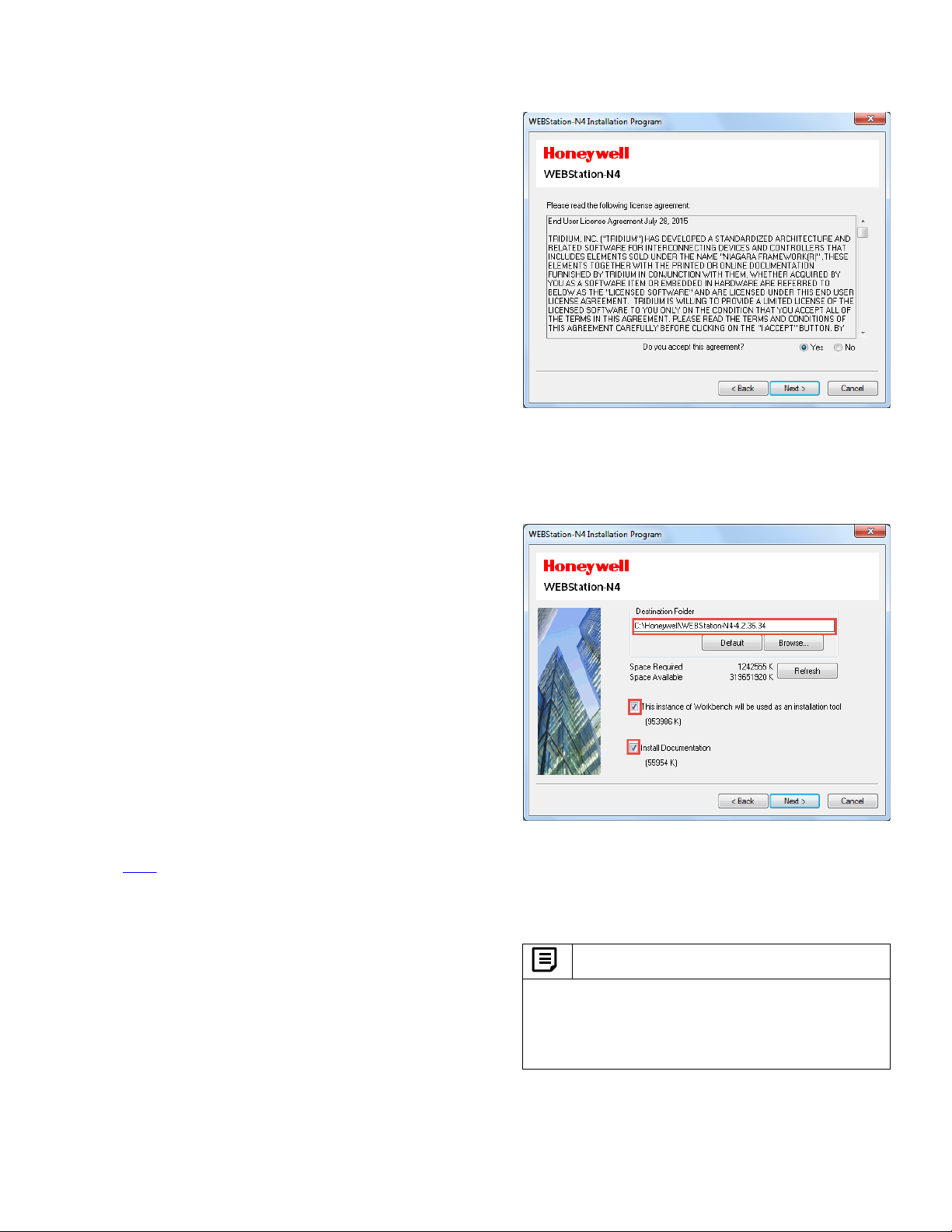
After selecting the setup for installation, proceed by
clicking ‘Next’ to accept the license agreement.
TM
should be installed as it hosts the
®
IV, 2 GHz or higher
TM
as support for newer operating systems
BACnet FF Controller
Figure 1: Installing WEBStation-N4TM
Select the installation location, (It will create a path in ‘C’
drive under ‘Honeywell’ folder by default)
TM
Figure 2: Installing WEBStation-N4
installation location)
Click ‘Next’ button to proceed after selecting appropriate
options. Wait until the installation gets finished.
Note:
(selecting
It is recommended to secure the WEBStation-N4 system
in order to make it resistant to the attacks.
Refer to the security documents available within
WEBStation-N4 software build to make WEBStation-N4
system secure.
31-00121—02 7
Page 10
BACnet FF Controller
Getting Started
Digital Signature
IMPORTANT
All the Honeywell WEBs software tools are now signed. Users can verify the signature using any OpenSSL tool.
Below are the steps to verify signature using OpenSSL community distribution.
Prerequisites:
• Download the Honeywell public key BuildingsCommonSupervisor.crt from location- same location as the
software release location
• Download the batch file “VerifyWEBsToolsSignature.bat” from location- same location as the software
elease location. This file has the commands to verify the module signature using the public key specified i
r
ep 1
St
• Download OPENSSL from this link- https://www.openssl.org/source/openssl-1.0.2o.tar.gz
• Extract the file using any ZIP utility to get the folder “openssl-1.0.2o”
• In the extracted folder find the file “openssl.cnf”
• Set Windows environment variable OPENSSL_CONF=<PATH TO openssl.cnf>, for example
OPENSSL_CONF=C:\openssl-1.0.2o\apps\openssl.cnf
Steps to verify the signature:
1. Place the files BuildingsCommonSupervisor.crt, VerifyWEBsToolsSignature.bat, WEBs tools modules and
signature file in the same location. For example: Following files are in one place
a. BuildingsCommonSupervisor.crt
b. VerifyWEBsToolsSignature.bat
c. honeywellSpyderTool.jar
d. honeywellSpyderTool.jar.sig
2. Open the command prompt and navigate to the location of the above files.
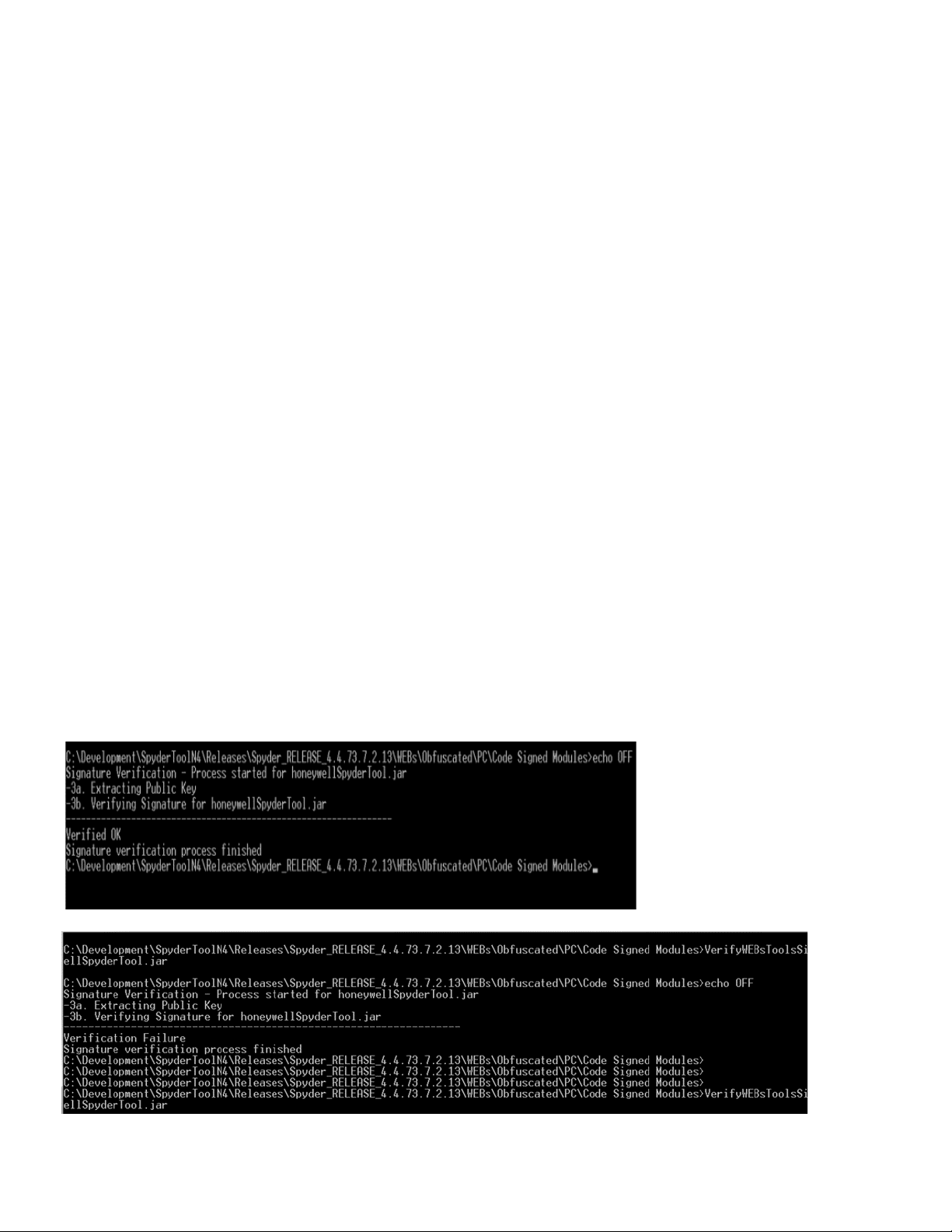
3. Execute the batch file VerifyWEBsToolsSignature.bat against a module for verifying its signature, for example
- C:\Spyder_RELEASE\ > VerifyWEBsToolsSignature.bat honeywellSpyderTool.jar
4. OpenSSL will verify this module’s signature and printout the below verification details:
n
5. If the Niagara module is compromised then user will get the below log, where verification has failed:
31-00121—02 8
Page 11
TB3026B Configuration Wizard is a user interface where a
user can set and adjust various types of parameters.
Important
BACnet FF Controller
Note:
Hash Value: Honeywell publishes the Hash Value with
the TB3026B Configuration Wizard module. It is
available as “honeywellTB3026BWizard_HashValue.txt”
with the released module.
The Hash Value generated at user’s end should match
the Hash Value published with the TB3026B
Configuration Wizard module. It is recommended to
perform this check in order to ensure the authenticity of
the TB3026B Configuration Wizard module.
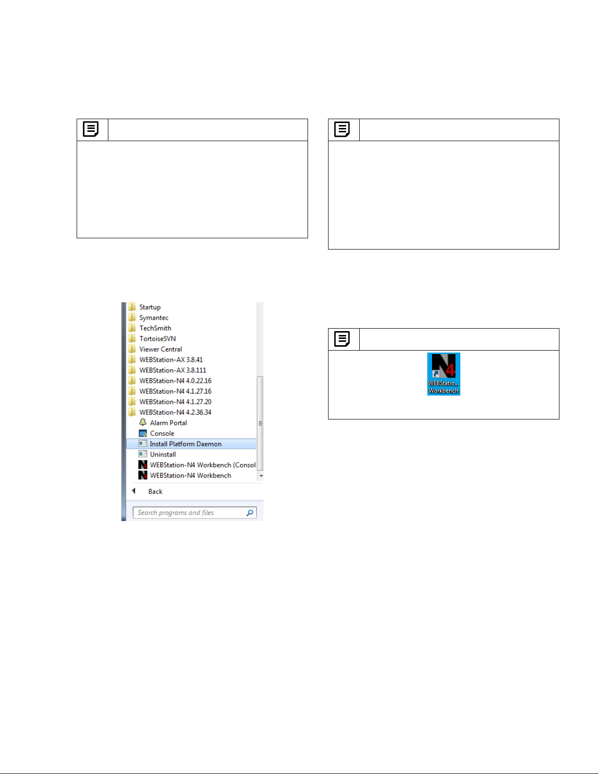
To start working with the configuration wizard, go to ‘Start’
menu, select ‘All Programs’, navigate to ‘WEBStation-N4
4.2.36.34’ folder and click on it. Click ‘Install Platform
Daemon’ as shown in Figure 3.
• If more than one version of WEBStation-N4 is
installed on the same PC, It is mandatory to install
Platform Daemon when switching from one version
of WEBStation-N4 to other.
It is not required to install Platform Daemon if the
same version of WEBStation-N4 needs to open
consecutively.
• If only single version of WEBStation-N4 is installed,
then it may not be required to install Platform
Daemon every time while opening WEBStation-N4.
After installing Platform Daemon completely, go to ‘Start’
menu again and select ‘All Programs, navigate to
‘WEBStation-N4 4.2.36.34’ folder and click on it. Click
‘WEBStation.’ It will open ‘WEBStation-N4’ window. Refer
to Figure 4.
Note:
‘WEBStation-N4’ can also be open by clicking an icon
named ‘WEBStation-N4 Workbench’ on the desktop
Figure 3: Installing Platform Daemon
31-00121—02 9
Page 12
BACnet FF Controller
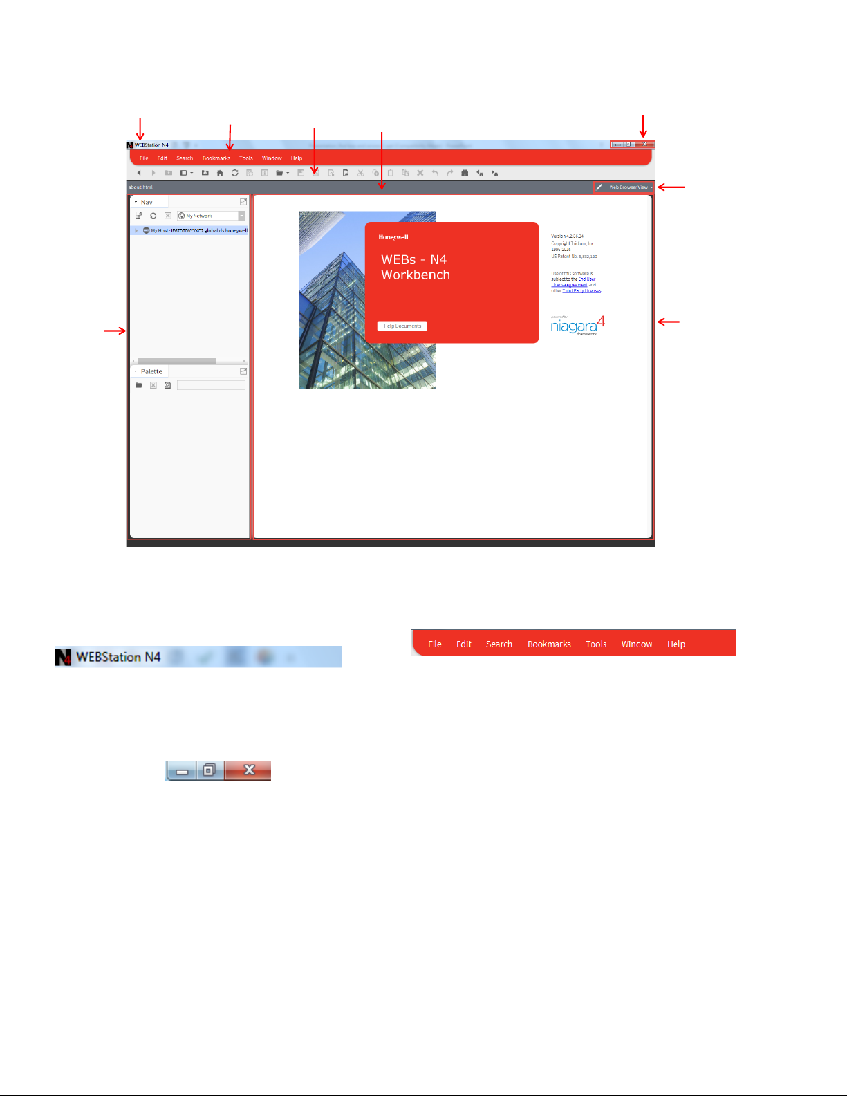
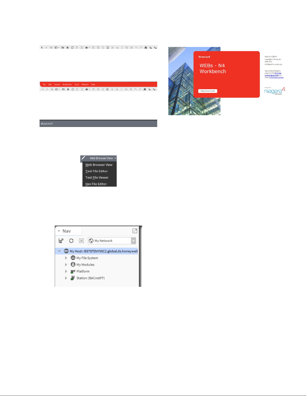
Title Bar
Menu Bar
Standard Toolbar
Path Bar
Controls
View Tab
Right Pane
Left Pane
Figure 4: WEBStation-N4TM – Getting Started
The field description for Figure 4is as follows:
1. Title Bar:
Top of the WEBStation interface is the Title bar. It displays
the title of the screen.
2. Controls
An application can be minimized, maximized and closed
with these controls.
3. Menu Bar
It displays heading for drop-down menus.
According to function, commands are group in to the menu
tabs. These are File, Edit, Search, Bookmarks, Tools,
Window, and Help.
I. File: A user can open, close and save the file,
directory, query, new tab, new window using File tab.
II. Edit: Cut, copy, paste, duplicate delete options are
available.
III. Search: A file can be searched and navigate from one
file to other file.
IV. Bookmarks: A user can add or manage bookmarks.
V. Tools: A user can maintain certificates, license,
migration and credential details.
VI. Window: A user can add/ hide Side Bar, Console
window, check Active Plug-in.
VII. Help: A user can get assist by clicking F1 or help tab.
10 31-00121—02
Page 13
BACnet FF Controller
4. Standard Tool Bar
Various functions can be accessed using this tool bar. It
provides a quick shortcut to frequently used functions.
5. Ribbon
It includes menu bar and standard toolbar.
6. Path Bar
A path of a particular function can be tracked using this.
7. View Tab
9. Right Pane
Details about Version, License and Certificate are found
over here.
It is used to switch between various views, such as, Html
View, Text File Editor, Text File Viewer, and Hex File
Editor.
8. Left pane
Nav tree details can be viewed over here.
31-00121—02 11
Page 14
BACnet FF Controller
TB3026B Configuration Wizard Initial
Setup
The TB3026B Configuration Wizard’s user interface
window is obtained by following these steps:
1. Connecting to platform
2. Adding new station
3. Starting/Running new station
4. Adding a BACnet network
5. Adding TB3026B device to the BACnet network
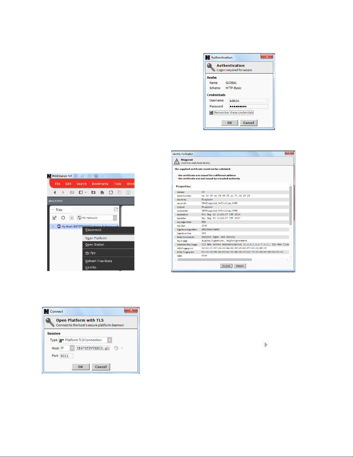
Connecting to Platform
To perform various operations, it is necessary to connect
to the Platform initially.
To connect Platform, follow the process:
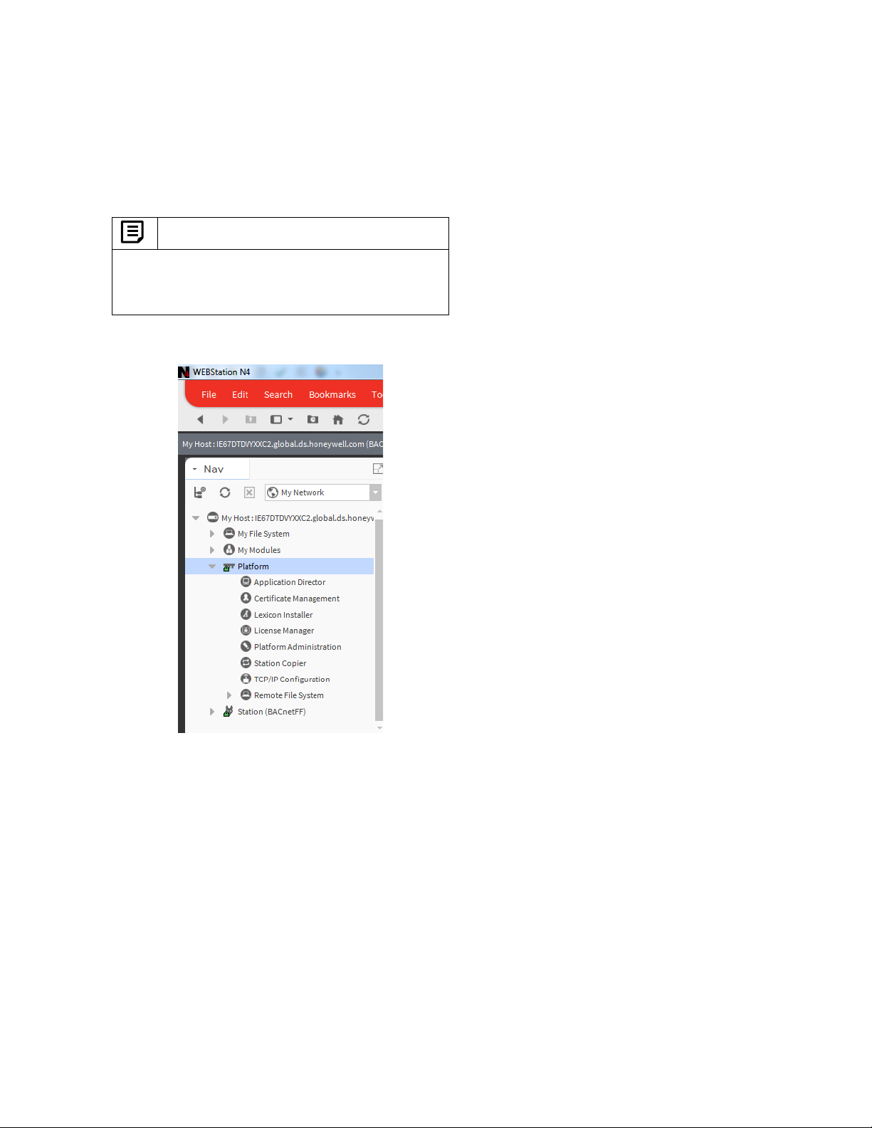
Navigate to ‘My Host: …’ in the Left pane, by right clicking
on it, select ‘Open Platform’. Refer to Figure 5.
Enter Username and Password and click ‘OK’
Figure 7: Authentication during connecting Platform
Figure 5: Open Platform
A window will pop up to connect to the Host’s secure
platform daemon. Click ‘OK’ to proceed.
Figure 6: Connect Platform
An Identity Verification window may pop up during the first
time configuration. Click ‘Accept’ to verify. (Refer to
Figure 8)
12 31-00121—02
Figure 8: Identity Verification during Connecting to
Platform
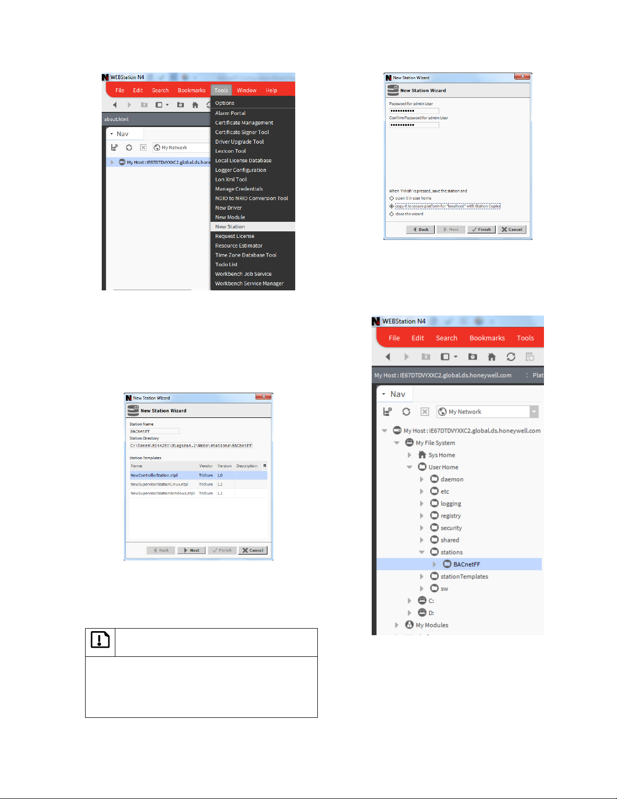
Adding New Station
The next stage is to add a new station under platform.
Different controllers can be added to the respective
network assigned to the station.
To add a new station:
• Navigate to the Platform by clicking sign of Host in
the left pane.
• Click ‘Tools’ tab on menu bar.
• Navigate to ‘New station’ and click on it.
Page 15
BACnet FF Controller
Figure 11: Entering Admin Password for New Station
Figure 9: Adding New Station
• After clicking ‘New Station’, it opens ‘New Station
Wizard, window. (Refer to Figure 10)
• Enter name in Station Name field. For example,
‘BACnetFF’ is added here. Station Directory displays a
path by default.
• Click ‘Next’
It creates a station at ‘My Host > My File System> User
Home > Stations > (created station)’. Refer to Figure 12.
• Click ‘Finish’ to complete action.
Figure 10: New Station Wizard Window
• Enter a password in the ‘Admin Password’ field. Enter
the same password in ‘Confirm Admin Password’ field.
Important:
Password must contain:
− at least 10 character(s)
− at least 1 digit(s)
− at least 1 lower case character(s)
− at least 1 upper case character(s)
31-00121—02 13
Figure 12: Location of New Station
(BACnetFF)
Page 16
BACnet FF Controller
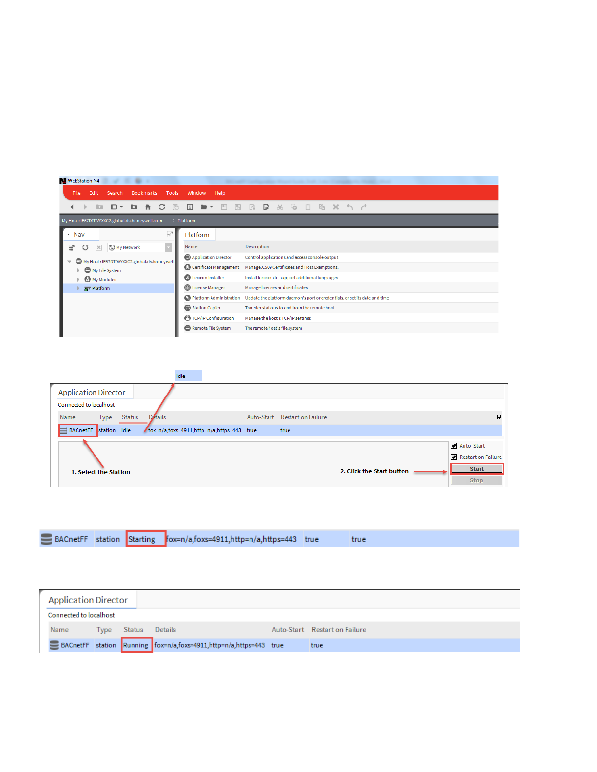
Starting New Station
To start configuration of controller, it is necessary to start
the station. The following is the process to start a newly
added station:
Double click on ‘Platform’, it opens a screen as shown in
Figure 13.
Double click on ‘Application Director’ at the right pane.
(Refer to Figure 13).
Figure 13: Application Director
Select the newly created station (‘BACnetFF’ in this case)
by just clicking on it. Status for this station will be Idle at
this stage.
Click ‘Start’ button as shown in Figure 14. After clicking
‘Start’, the ‘Status’ of this station will change to ‘Starting’ as
shown in Figure 15.
Figure 14: Selecting the Station to Start
Figure 15: Starting the Station
Figure 16: Started Station
14 31-00121—02
Page 17
Once the station is started, its status will change to
‘Running’ (Refer to Figure 16).
Double click on the started station, a ‘verification window
will pop up as shown in Figure 8. Click ‘Accept’ to proceed.
It opens an authentication window. Enter username and
password. Click ‘OK’ to proceed.
Note:
Check ‘Remember these credentials’ box to remember
the username and passwords so that it will not be
required to enter it every time during opening the
station.
Check newly added station as shown in Figure 17.
BACnet FF Controller
Figure 17: Newly added Station
31-00121—02 15
Page 18
BACnet FF Controller
Adding BACnet Network to Niagara
Network
TB3026B controller works with BACnet network.
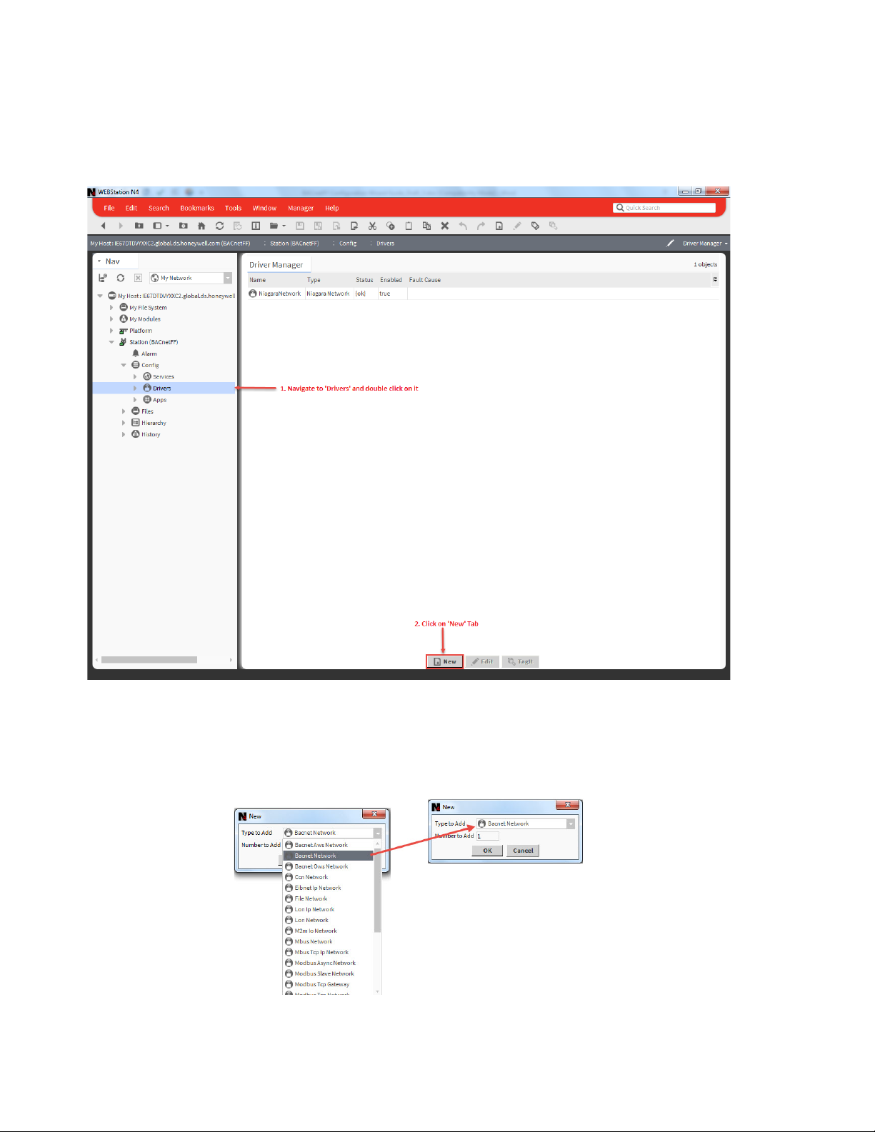
To add a BACnet network (Refer to Figure 18):
• Navigate to Drivers and double click on it.
• Click on ‘New’ tab
Figure 18: Adding BACnet Network
• A window will pop out as shown in Figure 19, asking
‘Type to Add’.
• Select ‘Bacnet Network’ from the drop down list.
Figure 19: Selecting BACnet Network to add
31-00121—02 16
Required number of networks can be added in
‘Number to Add’ field. (In this guide since only one
network is shown, Number is added as ‘1’)
Page 19
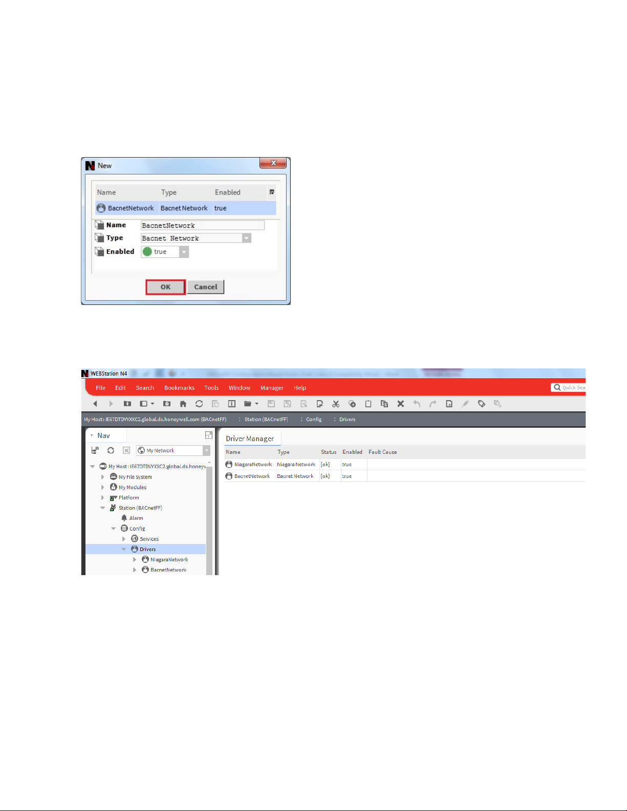
• Click ‘OK’ to proceed.
• Next, a new window will appear, showing ‘Name’,
‘Type’ and ‘Enabled’(keep its value to ‘True’). Refer to
Figure 20.
• Click ‘OK’.
Figure 20: Adding Specification to add BACnet
Network
BACnet FF Controller
• A newly added ‘BacnetNetwork’ can be seen under
‘Device manager’ on the right pane highlighted in
Amber color as shown in Figure 21
(An amber colored background highlight appears, as
BacnetNetwork is offline. Background will turn white when
it is online.)
Figure 21: Newly added BACnet Network
31-00121—02 17
Page 20
BACnet FF Controller
Adding TB3026B Controller to the
BACnet Network
• After adding a Bacnet Network to the Drivers, the next
step is to add a TB3026B controller to the Bacnet
Network.
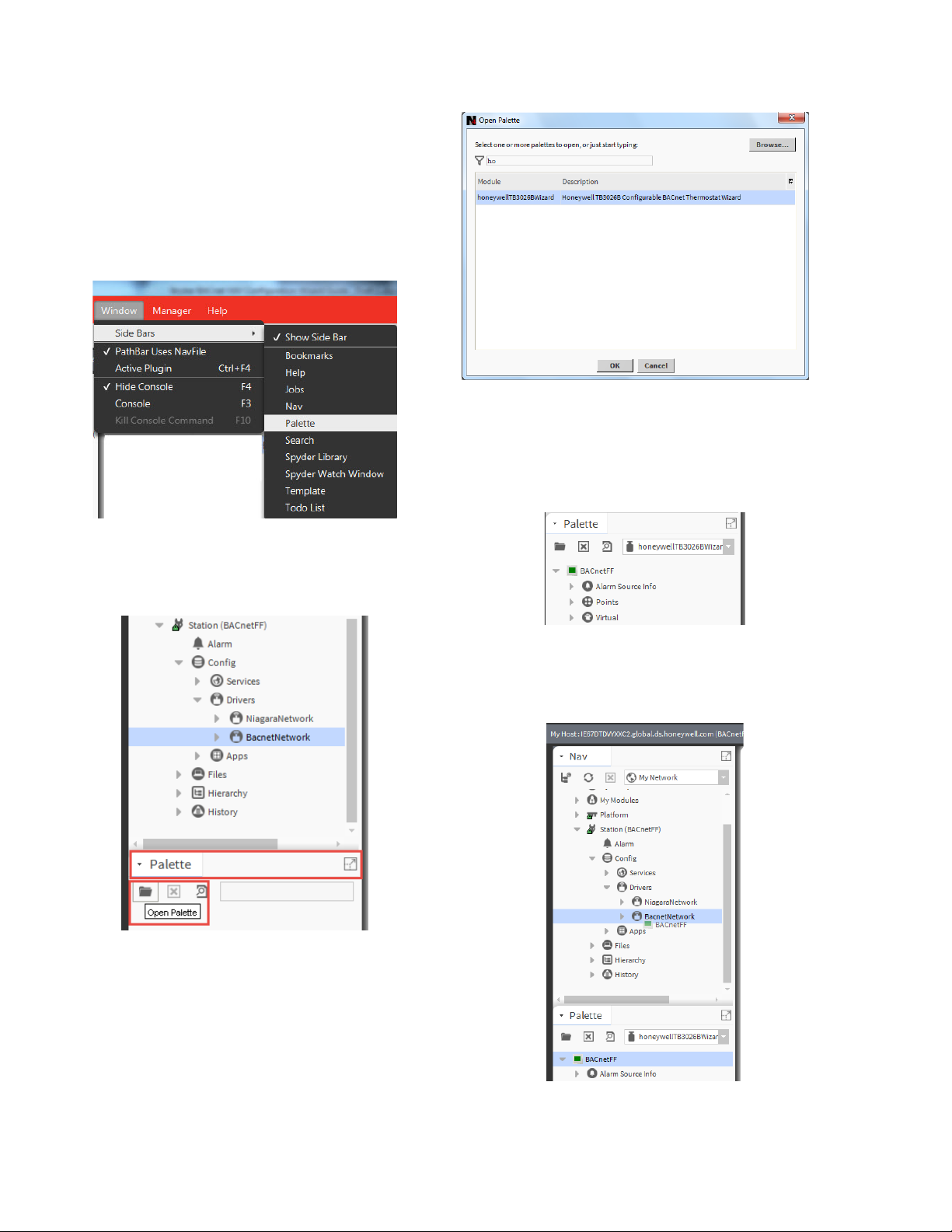
• Click on the ‘Window’ option in Menu bar; navigate to
‘Palette’ through sub menu of ‘Side Bars’.
(Refer to Figure 22).
Figure 24: Adding ‘honeywellTB3026BWizard’ to
BACnet Network
• After adding ‘honeywellTB3026BWizard’, it
reflects in the ‘Palette’ tab as ‘BACnetFF’ as seen
in Figure 25.
Figure 22: Adding Palette
• This will add a ‘Palette’ tab in the left pane. (Refer to
Figure 23). Click ‘Open Palette’ option.
Figure 23: Opening Palette
• An ‘Open Palette’ window will open. Find a module
named ‘honeywellTB3026BWizard’ as shown in
Figure 24, Select it and click ‘OK’ button to add into
the Palette.
Figure 25: BACnetFF in Palette TAB
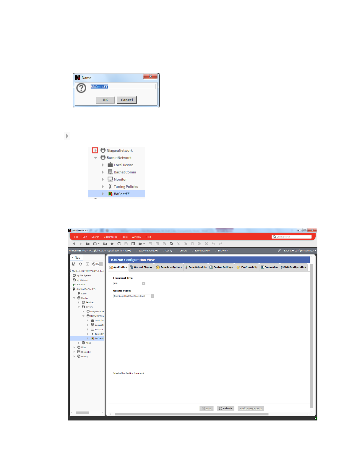
• Drag ‘BACnetFF’ and Drop it on ‘BacnetNetwork’
added under created station. Refer to Figure 26.
Figure 26: Drag and drop BACnetFF on BacnetNetwork
18 31-00121—02
Page 21
BACnet FF Controller
A window will pop up as ‘BACnetFF’ is dropped on
BacnetNetwork to name the controller. Enter the name
accordingly. In this guide, it is named as ‘BACnetFF’ as
shown in Figure 27.
Figure 27: Naming Controller
A newly added TB3026B controller can be seen by
clicking sign as shown in Figure 28.
Figure 28: Location of Controller
TB3026B Configuration Wizard
To start working with the TB3026B wizard, navigate to
Bacnet Network (Refer to Figure 28). Double click on
added controller (here, ‘BACnetFF’). It will open the
TB3026B Configuration Wizard window. .
31-00121—02 19
Page 22
BACnet FF Controller
Figure 29: Opening TB3026B Configuration Wizard Screen
Field Description for TB3026B Configuration Wizard
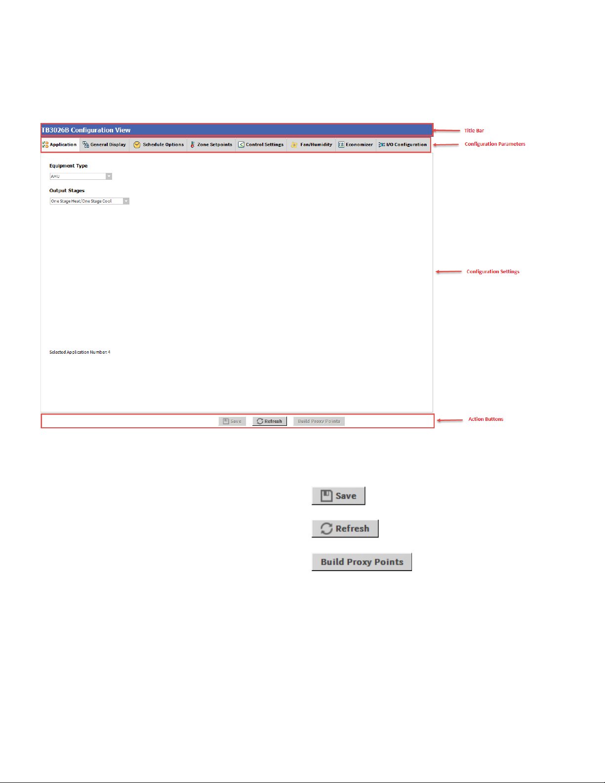
Figure 30: Field description for TB3026B Configuration Wizard Screen
1. Title Bar
It displays the name ‘TB3026B Configuration View’.
2. Configuration Parameters
It displays the list of setting buttons for various groups
of configuration parameters.
3. Configuration Settings
It displays Configuration settings as per the selected
group of parameters.
4. Action Buttons
It displays following buttons:
It is used to save the configuration
settings.
It is used to reset actions to its
default value.
It is used to generate proxy
points under TB3026B controller "points" folder for the
selected configuration.
20 31-00121—02
Page 23
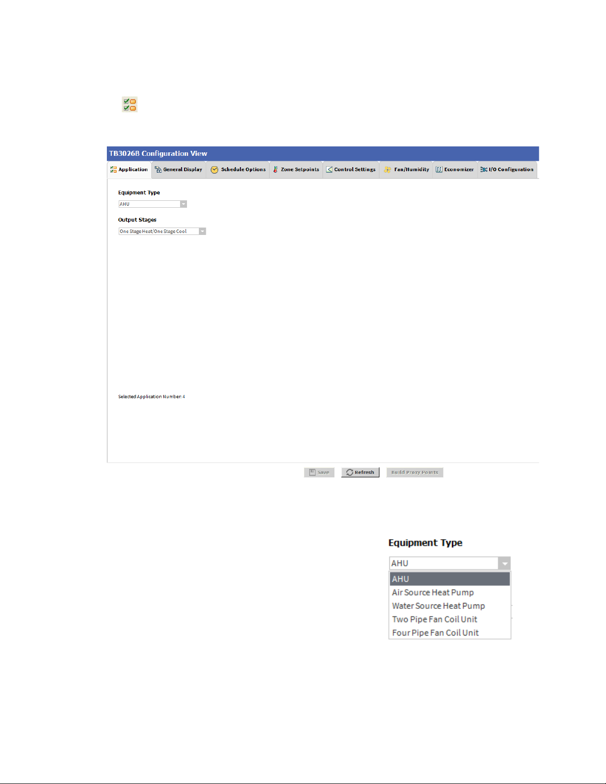
APPLICATIONS
Application is the first tab of the Configuration Wizard.
The Application screen allows a user to select the required
Equipment Type.
BACnet FF Controller
Figure 31: Application Screen
Equipment Type
A user can select the required equipment type through this
option. This is a fundamental setting in a configuration as
selection of various other parameters from the different
settings depend on the Equipment Type.
A required Equipment Type can be selected from the
following:
1. AHU
2. Air Source Heat Pump
3. Water Source Heat Pump
4. Two Pipe Fan Coil Unit
5. Four Pipe Fan Coil Unit
31-00121—02 21
Figure 32: Equipment Type
Page 24
BACnet FF Controller
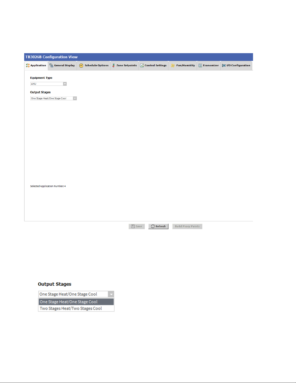
AHU
Figure 33: AHU window
Output Stages
Equipment Type ‘AHU’ consists of two types of ‘Output
Stages’
1. One Stage Heat/One Stage Cool
2. Two Stage Heat/Two Stage Cool
22 31-00121—02
One Stage Heat/One Stage Cool: Select this option if
One stage of cooling and one stage of Heating is required
in the application.
Two Stage Heat/Two Stage Cool: Select this option if
Two stages of cooling and two stages of Heating are
required in the application.
Page 25
BACnet FF Controller
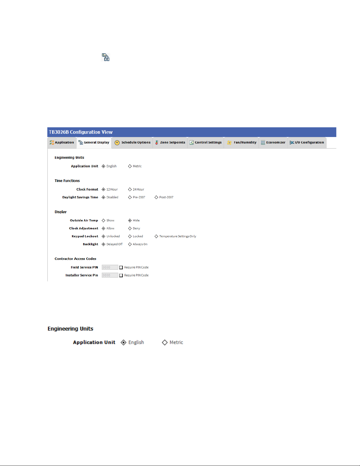
General Display
Click ‘General Display’ to view the general display
settings. The following parameters are used to configure
the controller’s display settings.
1. Engineering Units
2. Time Functions
3. Display
4. Contractor Access Codes
Figure 34: General Display Screen (AHU)
Engineering Units
Application Unit: The application units contain two
options to change the controller’s units. By default, the
controller’s application units are set to ‘English’. Application
Units can be changed to ‘English’ or ‘Metric’.
31-00121—02 23
Page 26
BACnet FF Controller
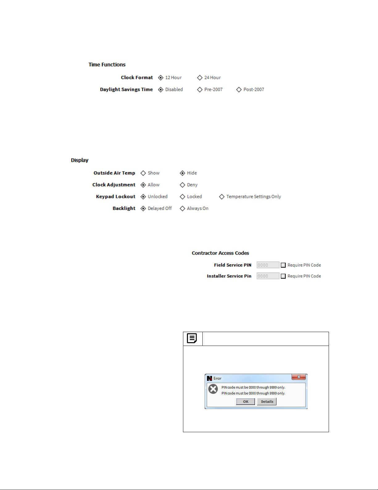
Time Function
Clock Format: A user can select a clock format as
12-hour format or 24-hour format.
Display
This feature allows a user to select the Display settings.
Outside Air Temp: A user has an option to hide/show an
outside air temperature.
Clock Adjustment: This option allows a user to
enable/disable the clock adjustment on the controller
display.
Keypad Lockout: This option allows a user to lock/unlock
the clock adjustment.
When an option, ‘Temperature Settings Only’ is selected, a
user can only set the temperature through keypad.
Backlight: A user can keep the backlight always on or set
to delayed off through this option.
Daylight Savings Time: This feature enables to select the
Daylight Savings Time settings. By default, Daylight
Savings Time is set to ‘Disabled’. Daylight Savings Time
can be changed to ‘Pre-2007’ or ‘Post-2007’.
Contractor Access Codes
An access to the controller can be restricted with the help
of Access Codes.
Field Service Pin and Installer Service Pin can be set.
These codes should be enabled to restrict an access to the
controller.
Note:
A user can set only numerical PIN code for ‘Field
Service Pin’ and ‘Installer Service Pin’. PIN codes
should be set within 0000 – 9999. The following Error
Window pops up if this field is left blank after selecting.
Note: When error message pops up, it displays the text
field twice in the error window.
24 31-00121—02
Page 27
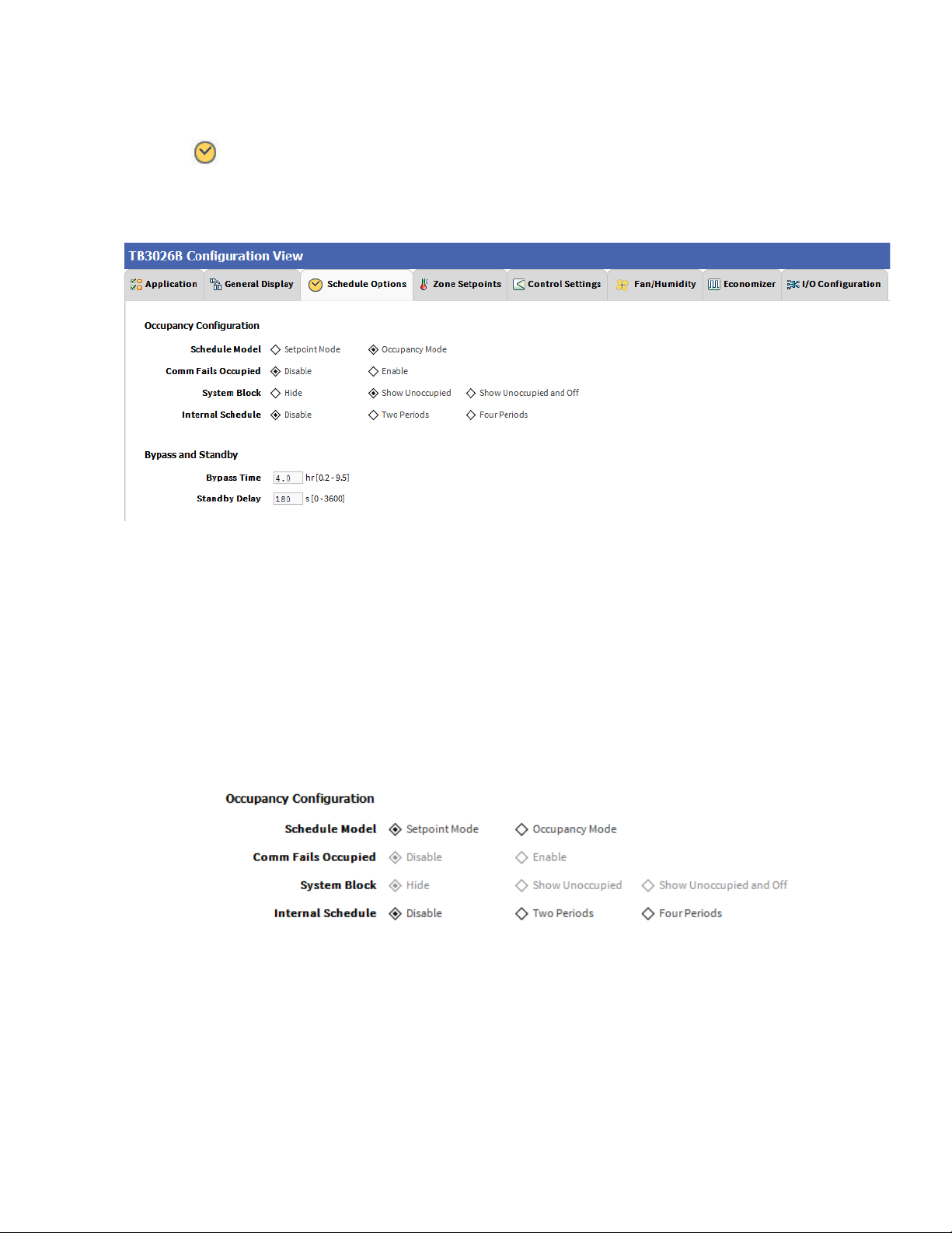
Schedule Options
‘Schedule’ tab displays Schedule options.
The following parameters are used to configure the
schedule options (i.e. Occupancy Configuration and
Bypass and Standby).
BACnet FF Controller
Figure 35: Schedule Options Screen (AHU)
Occupancy Configuration
Schedule Model: A user can set the device’s schedule
model as;
1. Setpoint Mode or
2. Occupancy Mode
Setpoint Mode: In setpoint mode, the controller logically
emulates residential thermostats. The space temperature
is controlled to "SP Mode Cooling SP" and "SP Mode
Heating SP". Each schedule period consists of a start time,
a heating setpoint, and a cooling setpoint.
Occupancy Mode: By default, ‘Schedule Model’ is in
‘Occupancy Mode’. The system will be switched to
‘Occupied Mode’ when the occupancy sensor detects
occupancy. Occupied Mode allows a user to configure
‘Comm Fails Occupied’, ‘System Block’ & ‘Internal
Schedule’ settings.
If a user selects ‘Setpoint Mode’ from the available
‘Schedule Model’, the fields for ‘Comm Fails Occupied’
and ‘System Block’ settings become disabled.
31-00121—02 25
Page 28
BACnet FF Controller
Comm Fails Occupied: It allows a user to switch the
system in Occupied Mode in case of MS/TP
communication failure. If the MS/TP communication fails,
the system enters into Occupied Mode when this option is
selected as ‘Enable’, otherwise the system remains in its
current state when this option is selected as ‘Disable’.
System Block: The System Block is hidden when the
schedule model is in ‘Setpoint Mode’. When the schedule
model is in ‘Occupancy Mode’, it allows a user to switch
between the available options. Selecting “Show
Unoccupied/Off” places the controller in unoccupied state.
Internal schedule: It can be configured in both Occupancy
Mode & Setpoint Mode. By default, ‘Internal Schedule’ is
‘Disable’.
If the internal schedule is ‘Disable’, a user can adjust the
setpoint (within setpoint limits).
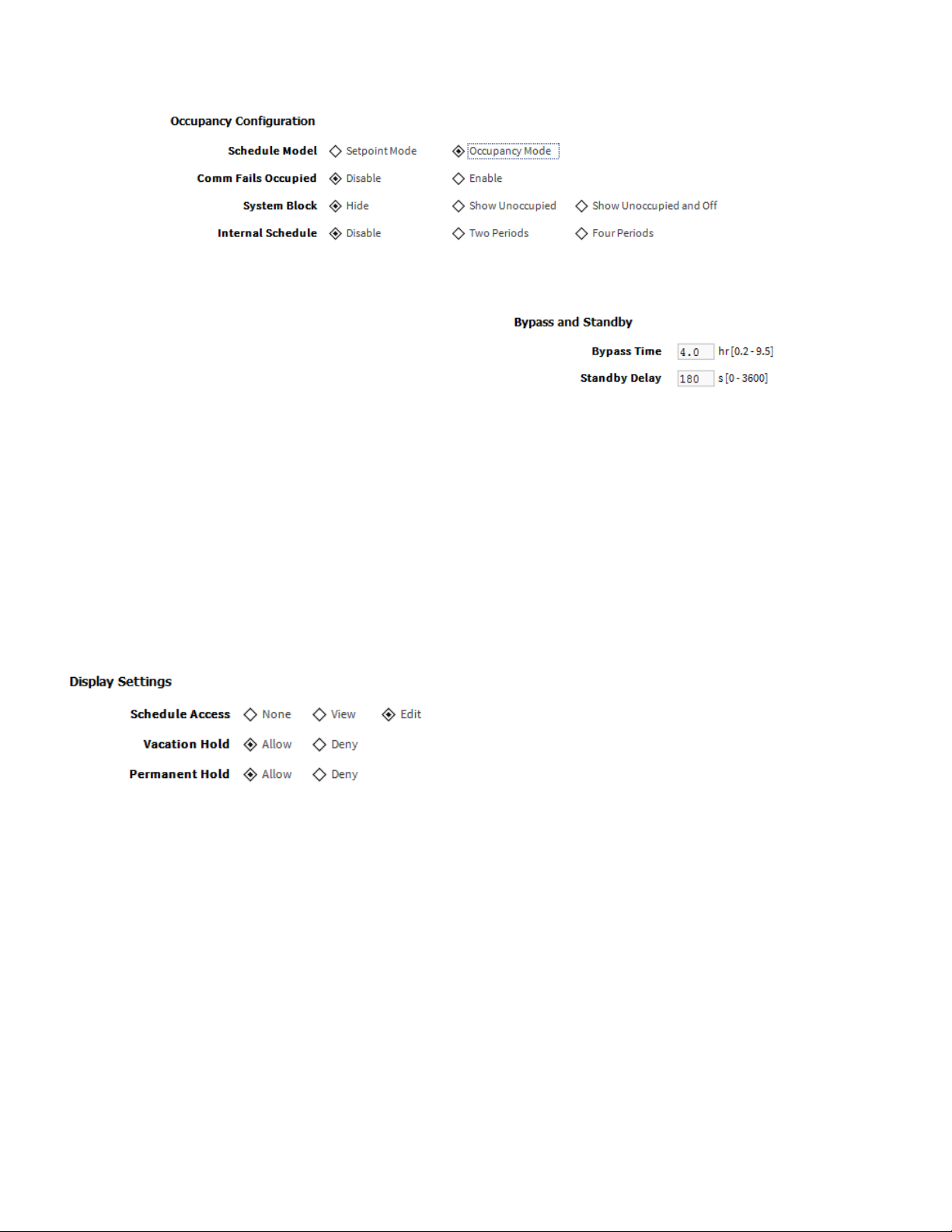
Display Settings
When a user selects, ‘Two Periods’ or ‘Four Periods’
options an additional ‘Display Settings’ appears as follows:
Bypass and Standby
Bypass Time: In the Unoccupied state, it forces the
controller into the occupied state for up to 4 hours (default
value). The override time limit is adjustable from a
minimum of 0.2 hours to a maximum of 9.5 hours.
Standby Delay: In Occupied Mode, if any window or door
is opened and closed with no motion detected after the
time mentioned for the Standby Delay, the room status
switches to Standby state. The default value is 180
seconds.
Schedule Access: When a user selects ‘Edit’, it allows a
user to view and edit the schedule and when a user selects
‘View’, it allows a user to view the schedule. When a user
selects ‘None’, it will not allow a user to view or edit the
schedule.
Vacation Hold: It allows/denies a user to override the
scheduled setpoint from TB3026B display to “Vacation
Hold”.
Permanent Hold: It allows/denies a user to override the
scheduled setpoint from TB3026B display to “Permanent
Hold”.
26 31-00121—02
Page 29
BACnet FF Controller
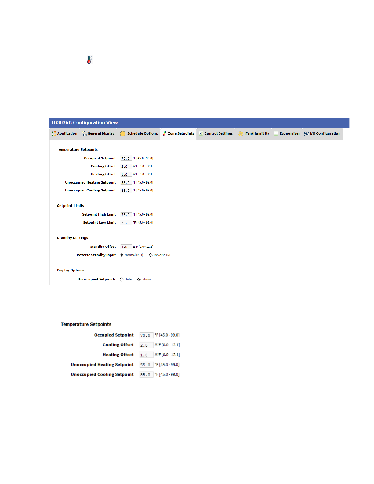
Zone Setpoints
Zone Setpoints , allows a user to set the following
parameters as per the requirement:
1. Temperature Setpoints
2. Setpoint Limits
3. Standby Settings
4. Display Options
Figure 36: Zone Setpoints Screen (Occupancy Mode)
Temperature Setpoints
Occupied Setpoint: It is a setpoint in Occupied Mode.
Enter the value within the range of 45 ºF to 99 ºF. The
default value is 70ºF.
Cooling Offset: In the Occupied state, the cooling setpoint
is calculated as cooling offset plus occupied setpoint. Enter
31-00121—02 27
the value within the range of 0ΔºF to 12.1ΔºF. The default
value is 2 ΔºF.
Heating Offset: In the Occupied state, the heating setpoint
is calculated as heating offset minus occupied setpoint.
Enter the value within the range of 0ΔºF to 12.1ΔºF. The
default value is 1 ΔºF.
Unoccupied Heating Setpoint: It is a setpoint for Heating
in Unoccupied mode. Enter the value within the range of
45 ºF to 99 ºF. The default value is 55 ºF.
Unoccupied Cooling Setpoint: It is a setpoint for Cooling
in Unoccupied mode. Enter the value within the range of
45 ºF to 99 ºF. The default value is 85 ºF.
Page 30
BACnet FF Controller
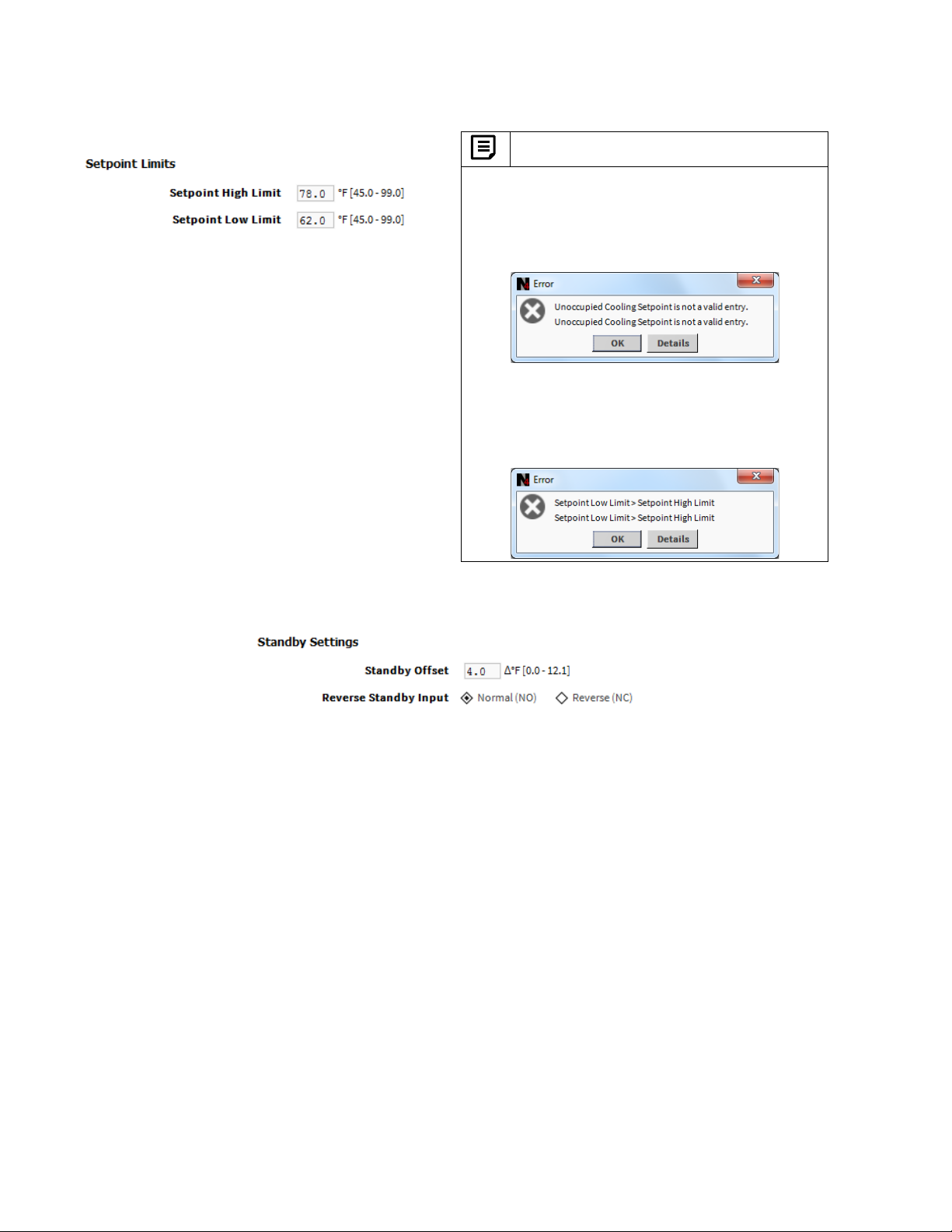
Setpoint Limits
Setpoint High Limit: A user can enter a Setpoint High
Limit in Occupied Mode within the range of 45 ºF to 99 ºF.
The default value is 78 ºF.
Setpoint Low Limit: A user can enter a Setpoint Low Limit
in Occupied Mode within the range of 45 ºF to 99 ºF. The
default value is 62 ºF.
Note:
1. Unoccupied Cooling Setpoint should always be set
GREATER than Unoccupied Heating Setpoint.
Following Error window appears if Unoccupied
Cooling Setpoint is set lower than Unoccupied
Heating Setpoint.
2. Setpoint High Limit should always be set
GREATER than Setpoint Low Limit.
Following Error window appears if Setpoint High
Limit is set lower than Setpoint low Limit.
Standby Settings
Standby state is a power-saving function of Occupancy
mode. It occurs when the space is scheduled as Occupied,
but sensors detect (When the Standby input is active)
there are no humans in the space.
Standby Offset: In this case, the Standby Offset relaxes
the occupied setpoints. The value of the Standby Offset
[SO] can be set between a minimum of 0ΔºF and a
maximum of 12.1ΔºF degrees. The default value is 4 ΔºF.
Reverse Standby Input: It allows a user to configure two
types of inputs, ‘Normally Open (NO)’ and ‘Normally Close
(NC)’.
28 31-00121—02
Page 31

BACnet FF Controller
Display Options
Unoccupied Setpoints: It allows a user to either ‘Hide’ or
‘Show’ the unoccupied setpoint.
When a user selects Schedule Mode under the ‘Schedule Options’ tab to ‘Setpoint Mode’, the ‘Zone Setpoints’
configuration window appears as follows:
Figure 37: Zone Setpoint Screen (Setpoint Mode)
31-00121—02 29
Page 32

Control Settings
‘Control Settings’ allows a user to configure following
settings:
1. Cooling PI Control
2. Heating PI Control
3. Compressor Settings
BACnet FF Controller
Figure 38: Control Settings Screen (AHU)
31-00121—02 30
Page 33

BACnet FF Controller
Cooling PI Control
Proportional Constant K
: A user can enter a value for Kp
p
within the range of 10 to 40. The default value is 20.
Integral Constant K
: A user can enter a value for Ki
i
within the range of 0.50 to 2. The default value is 1.
OAT Lockout Setpoint: Cooling PI control will lockout
when outside Temperature decreases below OAT
(Cooling) Lockout Setpoint. The default value is 55 ºF.
Heating PI Control
Proportional Constant K
: A user can enter a value for Kp
p
within the range of 10 to 40. The default value is 20.
Integral Constant K
: A user can enter a value for Ki
i
within the range of 0.50 to 2. The default value is 1.
OAT Lockout Setpoint: Heating PI control will lockout
when outside Temperature increases above OAT (Heating)
Lockout Setpoint. The default value is 62 ºF.
Compressor Settings
Cycle Time: The Compressor Cycle Time is adjustable, it
ranges from minimum of 8 minutes, and a maximum of 30
minutes. The default value is 20 minutes.
Minimum On/Off Time: It is a minimum time for the
compressor to stay On/Off. The default value is 3 minutes.
31-00121—02 31
Page 34

BACnet FF Controller
Fan / Humidity
‘Fan / Humidity’ allows a user to configure the
following settings:
1. Fan Operation
2. Humidity Control
3. Filter Alarm
Figure 39: Fan/Humidity Screen (AHU)
Fan Operation
Fan Mode Control: During Setpoint Mode and Occupancy
Mode, the fan can be configured to operate based on the
selected Fan Mode Control as describe below:
Auto: When this option is selected, Fan cycles ON when:
1. Cooling or heating is selected or
2. During Unoccupied mode only when called to run
by cooling or heating demand.
On: When this option is selected the fan runs continuously
for ventilation.
On Cool/Auto Heat: When this option is selected the fan
runs continuously in cooling mode. In heating mode the fan
cycles on only when the heating signal calls for the fan to
run.
32 31-00121—02
Page 35

BACnet FF Controller
Humidity Control
Fan Circulation Cycle: When a user selects the ‘Enable’
option from Fan Circulation Cycle, it allows a user to edit
the Trigger Setpoint, Reset Deadband, and Fan On/Off
Cycle Time.
Trigger Setpoint & Reset Deadband: When sensed
humidity equals or exceeds humidity trigger setpoint, the
fan cycles ON/OFF at low speed until sensed humidity
drops below the trigger setpoint minus the reset deadband.
Fan On Cycle Time: This field allows a user to enter a
time for fan ON cycle when stratification and humidity
control is active. The default value is 300 seconds.
Fan Off Cycle Time: This field allows a user to enter a
time for fan OFF cycle when stratification and humidity
control is active. The default value is 1800 seconds.
Filter Alarm
Runtime Hours: A filter alarm activates after the Runtime
Hours mentioned in this field. The default value is 3000
hours.
31-00121—02 33
Page 36

BACnet FF Controller
Economizer
Select Economizer from Configuration parameters. It
is used to configure the economizer settings in TB3026B
controller.
Figure 40: Economizer Screen (AHU)
Configuration
Minimum Position: When either the occupied command
or the After-hours Timer is ON, the current minimum
position is set to the specified Economizer Minimum
Position; otherwise, it is zero. The default minimum
position is 20%.
Outside Air Lockout: The economizer is forced to
Minimum position when Outside Air Temperature goes
above the Outside Air Lockout setpoint. The default value
is 68º F.
Supply Air Low Limit: The economizer is forced to
Minimum position when Supply Temperature goes below
the Supply Air Low Limit. The default value is 45º F.
34 31-00121—02
Page 37

BACnet FF Controller
I/O Configurations
Select I/O Configurations from Configuration
parameters. This configuration is mainly used for Terminal
Assignment & Output Configuration.
Figure 41:I/O Configurations Screen (AHU)
Terminal Assignment
After completing the AHU configuration, selected inputs
and outputs get automatically assigned to the TB3026B
controller’s input and output terminals. However, a user
can assign the outputs as ‘Economizer Open’ &
‘Economizer Close ’to BO-4 & BO-5 and inputs as ‘BMS
Sensor’ or ‘Remote Space Temp’ or ‘Outdoor Air Temp’ to
AI/BI0 respectively.
31-00121—02 35
Page 38

BACnet FF Controller
Figure 42: Terminal Assignment View (AHU)
Output Configuration
When a user assigns the outputs, ‘Economizer Open’ and
‘Economizer Close’ to BO-4 and BO-5 respectively,
‘Economizer Damper Stroke Time’ can be mentioned in the
field ‘Output Configuration’. The default value is 3 seconds.
When ‘Output Stage’ is selected as ‘Two Stages Heat/Two Stages Cool’, the ‘Terminal Assignment’ view changes
as follows:
36 31-00121—02
Page 39

Air Source Heat Pump
BACnet FF Controller
Figure 43: Air Source Heat Pump Window
Output Stages
Equipment Type ‘Air Source Heat Pump’ consists of two
types of ‘Output Stages’. Required type of output stages
can be selected from the following available options:
One Compressor Stage and One Aux Heat Stage:
Select this option if One stage of compressor and one
stage of Auxiliary Heating is required in the application
31-00121—02 37
One Compressor Stage and Two Aux Heat Stage:
Select this option if Two stages of Compressors and Two
stages of Auxiliary Heating are required in the application
Fan Speeds
A user can select Two types of ‘Fan Speeds’ when the
output stage is configured as ‘One Compressor Stage and
One Aux Heat Stage’.
1. Single Speed Fan
2. Three Speed Fan
Page 40

BACnet FF Controller
General Display
Click ‘General Display’ to view the general display
settings. The following parameters are used to configure
the controller’s display settings.
1. Engineering Units
2. Time Functions
3. Display
4. Contractor Access Codes
Figure 44: General Display Screen (Air Source Heat Pump)
Engineering Units
Application Unit: The application units contain two
options to change the controller’s units. By default, the
controller’s application units are set to ‘English’. Application
units can be changed to ‘English’ or ‘Metric’.
38 31-00121—02
Page 41

Time Function
BACnet FF Controller
Clock Format: A user can select a clock format as
12-hour format or 24-hour format.
Display
This feature allows a user to select the Display settings.
Outside Air Temp: A user has an option to hide/show an
outside air temperature.
Clock Adjustment: This option allows a user to
enable/disable the clock adjustment on the controller
display.
Keypad Lockout: This option allows a user to lock/unlock
the clock adjustment.
When an option, ‘Temperature Settings Only’ is selected, a
user can only set the temperature through keypad.
Backlight: A user can keep the backlight always on or set
to delayed off through this option.
Daylight Savings Time: This feature enables to select the
Daylight Savings Time settings. By default, Daylight
Savings Time is set to ‘Disabled’. Daylight Savings Time
can be changed to ‘Pre-2007’ or ‘Post-2007’.
Contractor Access Codes
An access to the controller can be restricted with the help
of Access Codes.
Field Service Pin and Installer Service Pin can be set.
These codes should be enabled to restrict an access to the
controller.
Note:
A user can set only numerical PIN code for ‘Field
Service Pin’ and ‘Installer Service Pin’. PIN codes
should be set within 0000 – 9999. The following Error
Window pops up if this field is left blank after selecting.
31-00121—02 39
Page 42

BACnet FF Controller
Schedule Options
‘Schedule’ tab displays Schedule options.
The following parameters are used to configure the
schedule options (i.e. Occupancy Configuration and
Bypass and Standby)
Figure 45: Schedule Options Screen (Air Source Heat Pump)
Occupancy Configuration
Schedule Model: A user can set the device’s schedule
model as;
1. Setpoint Mode or
2. Occupancy Mode
Setpoint Mode: In setpoint mode, the controller logically
emulates residential thermostats. The space temperature
is controlled to "SP Mode Cooling SP" and "SP Mode
Heating SP". Each schedule period consists of a start time,
a heating setpoint, and a cooling setpoint.
Occupancy Mode: By default, ‘Schedule Model’ is in
‘Occupancy Mode’. The system will be switched to
‘Occupied Mode’ when the occupancy sensor detects
occupancy. Occupied Mode allows a user to configure
‘Comm Fails Occupied’, ‘System Block’ & ‘Internal
Schedule’ settings.
If a user selects ‘Setpoint Mode’ from the available
‘Schedule Model’, the fields for ‘Comm Fails Occupied’
and ‘System Block’ settings become disabled.
40 31-00121—02
Page 43

Comm Fails Occupied: It allows a user to switch the
system in Occupied Mode in case of MS/TP
communication failure. If the MS/TP communication fails,
the system enters into Occupied Mode when this option is
selected as ‘Enable’, otherwise the system remains in its
current state when this option is selected as ‘Disable’.
‘Enable’, and remains in its current state when this option
is selected as ‘Disable’.
System Block: The System Block is hidden when the
schedule model is in ‘Setpoint Mode’. When the schedule
model is in ‘Occupancy Mode’, it allows a user to switch
between the available options. Selecting “Show
Unoccupied/Off” places the controller in unoccupied state.
Internal schedule: It can be configured in both Occupancy
Mode & Setpoint Mode. By default, ‘Internal Schedule’ is
‘Disable’.
If the internal schedule is ‘Disable’, a user can adjust the
setpoint (within setpoint limits).
Display Settings
When a user selects, ‘Two Periods’ or ‘Four Periods’
options an additional ‘Display Settings’ appears as follows:
BACnet FF Controller
Bypass and Standby
Bypass Time: In the Unoccupied state, it forces the
controller into the occupied state for up to 4 hours (default
value). The override time limit is adjustable from a
minimum of 0.2 hours to a maximum of 9.5 hours.
Standby Delay: In Occupied Mode, if any window or door
is opened and closed with no motion detected after the
time mentioned for the Standby Delay, the room status
switches to Standby state. The default value is 180
seconds.
Schedule Access: When a user selects ‘Edit’, it allows a
user to view and edit the schedule and when a user selects
‘View’, it allows a user to view the schedule. When a user
selects ‘None’, it will not allow a user to view or edit the
schedule.
Vacation Hold: It allows/denies a user to override the
scheduled setpoint from TB3026B display to “Vacation
Hold”.
Permanent Hold: It allows/denies a user to override the
scheduled setpoint from TB3026B display to “Permanent
Hold”.
31-00121—02 41
Page 44

BACnet FF Controller
Zone Setpoints
Zone Setpoints , allows a user to set the following
parameters as per the requirement:
1. Temperature Setpoints
2. Setpoint Limits
3. Standby Settings
4. Display Options
Figure 46: Zone Setpoints Screen (Occupancy Mode)
Temperature Setpoints
Occupied Setpoint: It is a setpoint in Occupied Mode.
Enter the value within the range of 45 ºF to 99 ºF. The
default value is 70ºF.
Cooling Offset: In the Occupied state, the cooling setpoint
is calculated as cooling offset plus occupied setpoint. Enter
42 31-00121—02
the value within the range of 0ΔºF to 12.1ΔºF.The default
value is 2 ΔºF.
Heating Offset: In the Occupied state, the heating setpoint
is calculated as heating offset minus occupied setpoint.
Enter the value within the range of 0ΔºF to 12.1ΔºF. The
default value is 1 ΔºF.
Unoccupied Heating Setpoint: It is a setpoint for Heating
in Unoccupied mode. Enter the value within the range of
45 ºF to 99 ºF. The default value is 55 ºF.
Unoccupied Cooling Setpoint: It is a setpoint for Cooling
in Unoccupied mode. Enter the value within the range of
45ºF to 99ºF.The default value is 85 ºF.
Page 45

BACnet FF Controller
Setpoint Limits
Setpoint High Limit: A user can enter a Setpoint High
Limit in Occupied Mode within the range of 45 ºF to 99 ºF.
The default value is 78ºF.
Setpoint Low Limit: A user can enter a Setpoint Low Limit
in Occupied Mode within the range of 45 ºF to 99 ºF. The
default value is 62ºF.
Note:
1. Unoccupied Cooling Setpoint should always be set
GREATER than Unoccupied Heating Setpoint.
Following Error window appears if Unoccupied
Cooling Setpoint is set lower than Unoccupied
Heating Setpoint.
2. Setpoint High Limit should always be set
GREATER than Setpoint Low Limit.
Following Error window appears if Setpoint High
Limit is set lower than Setpoint low Limit.
Standby Settings
Standby state is a power-saving function of Occupancy
mode. It occurs when the space is scheduled as Occupied,
but sensors detect (When the Standby input is active)
there are no humans in the space.
Standby Offset: In this case, the Standby Offset relaxes
the occupied setpoints. The value of the Standby Offset
[SO] can be set between a minimum of 0ΔºF and a
maximum of 12.1ΔºF degrees. The default value is 4 ΔºF.
Reverse Standby Input: It allows a user to configure two
types of inputs, ‘Normally Open (NO)’ and ‘Normally Close
(NC)’.
31-00121—02 43
Page 46

BACnet FF Controller
Display Options
When a user selects Schedule Model under the ‘Schedule Options’ tab to ‘Setpoint Mode’, the ‘Zone Setpoints’
configuration window appears as follows:
Figure 47: Zone Setpoint Screen (Setpoint Mode)
Unoccupied Setpoints: It allows a user to either ‘Hide’ or
‘Show’ the unoccupied setpoint.
44 31-00121—02
Page 47

BACnet FF Controller
Control Settings
‘Control Settings’ allows a user to configure following
settings:
1. Cooling PI Control.
2. Heating PI Control.
3. Aux Staged Heating
4. Compressor Settings.
Figure 48: Control Settings Screen (Air Source Heat Pump)
31-00121—02 45
Page 48

BACnet FF Controller
Cooling PI Control
Proportional Constant K
: A user can enter a value for Kp
p
within the range of 10 to 40. The default value is 20.
Integral Constant K
: A user can enter a value for Ki
i
within the range of 0.50 to 2. The default value is 1.
OAT Lockout Setpoint: Cooling PI control will lockout
when outside Temperature increases above OAT (Cooling)
Lockout Setpoint. The default value is 55 ºF.
Aux Staged Heating
Heating PI Control
Proportional Constant K
: A user can enter a value for Kp
p
within the range of 10 to 40. The default value is 20.
Integral Constant K
: A user can enter a value for Ki
i
within the range of 0.50 to 2. The default value is 1.
OAT Lockout Setpoint: Heating PI control will lockout
when outside Temperature decreases below OAT
(Heating) Lockout Setpoint. The default value is 62 ºF.
Compressor Settings
Cycle Time: The Cycle Time ranges from minimum of 8
minutes, and a maximum of 30 minutes. The default value
is 15 minutes.
Minimum On/Off Time: It is a minimum On/Off time for
the Auxiliary Heating. The default value is 3 minutes.
Cycle Time: The Compressor Cycle Time is adjustable; it
ranges from minimum of 8 minutes, and a maximum of 30
minutes. The default value is 20 minutes.
Minimum On/Off Time: It is a minimum time for the
compressor to stay On/Off. The default value is 3 minutes.
Reversing Valve: Depending upon heating/cooling
demand, a user can energize the Reversing Valve on
Heating or Cooling.
46 31-00121—02
Page 49

BACnet FF Controller
Fan / Humidity
‘Fan / Humidity’ allows a user to configure the
following settings:
1. Fan Operation
2. Humidity Control
3. Filter Alarm
Figure 49: Fan/Humidity Screen (Air Source Heat Pump)
Fan Operation
Fan Mode Control: During Setpoint Mode and Occupancy
Mode, the fan can be configured to operate based on the
selected Fan Mode Control as describe below:
Auto: When this option is selected, Fan cycles ON when:
1. Cooling or heating is selected or
2. During Unoccupied mode only when called to run
by cooling or heating demand.
On: When this option is selected the fan runs continuously
for ventilation.
On Cool/Auto Heat: When this option is selected the fan
runs continuously in cooling mode. In heating mode the fan
cycles on only when the heating signal calls for the fan to
run.
31-00121—02 47
Page 50

BACnet FF Controller
Humidity Control
Fan Circulation Cycle: When a user selects the ‘Enable’
option from Fan Circulation Cycle, it allows a user to edit
the Trigger Setpoint, Reset Deadband, and Fan On/Off
Cycle Time.
Trigger Setpoint & Reset Deadband: When sensed
humidity equals or exceeds humidity trigger setpoint, the
fan cycles ON/OFF at low speed until sensed humidity
drops below the trigger setpoint minus the reset deadband.
Fan On Cycle Time: This field allows a user to enter a
time for fan ON cycle when stratification and humidity
control is active. The default value is 300 seconds.
Fan Off Cycle Time: This field allows a user to enter a
time for fan OFF cycle when stratification and humidity
control is active. The default value is 1800 seconds.
Filter Alarm
Runtime Hours: A filter alarm activates after the Runtime
Hours mentioned in this field. The default value is 3000
hours.
48 31-00121—02
Page 51

BACnet FF Controller
Economizer
Select Economizer from Configuration parameters. It
is used to configure the economizer settings in TB3026B
controller
Figure 50: Economizer Screen (Air Source Heat Pump)
Configuration
Minimum Position: When either the occupied command
or the After-hours Timer is ON, the current minimum
position is set to the specified Economizer Minimum
Position; otherwise, it is zero. The default minimum
position is 20%.
Outside Air Lockout: The economizer is forced to
Minimum position when Outside Air Temperature goes
above the Outside Air Lockout setpoint. The default value
is 68º F.
Supply Air Low Limit: The economizer is forced to
Minimum position when Supply Temperature goes below
the Supply Air Low Limit. The default value is 45º F.
31-00121—02 49
Page 52

BACnet FF Controller
I/O Configurations
Select I/O Configurations from Configuration
parameters. This configuration is used for Terminal
Assignment & Output Configuration.
Figure 51: I/O Configurations Screen (Air Source Heat Pump)
Terminal Assignment
After completing the ‘Air Source Heat Pump’ configuration,
selected inputs and outputs get automatically assigned to
the TB3026B controller’s input and output terminals.
However, a user can assign the outputs as ‘Economizer
Open’ & ‘Economizer Close’ to BO-4 & BO-5 and inputs as
‘BMS Sensor’ or ‘Remote Space Temp’ or ‘Outdoor Air
Temp’ to AI/BI0 respectively.
Figure 52: Terminal Assignment View (Air Source Heat Pump)
50 31-00121—02
Page 53

BACnet FF Controller
Output Configuration
When a user assigns the outputs, ‘Economizer Open’ and
‘Economizer Close’ to BO-4 and BO-5 respectively,
‘Economizer Damper Stroke Time’ can be mentioned in the
field ‘Output Configuration’. The default value is 3 seconds.
When ‘Fan Speed’ is selected as ‘Three Speed Fan’, the ‘Terminal Assignment’ view changes as follows:
When ‘Output Stage’ is selected as ‘One Compressor Stage/Two Aux Stages’, the ‘Terminal Assignment’ view
changes as follows:
31-00121—02 51
Page 54

BACnet FF Controller
Water Source Heat Pump
Figure 53: Water Source Heat Pump Window
Output Stages
Equipment Type ‘Water Source Heat Pump’ consists of
two types of ‘Output Stages’
1. One Compressor Stage/One Aux Heat Stage
2. One Compressor Stage/Two Aux Heat Stages
52 31-00121—02
One Compressor Stage and One Aux Heat Stage:
Select this option if One stage of compressor and one
stage of Auxiliary Heating is required in the application
One Compressor Stage and Two Aux Heat Stage:
Select this option if Two stages of Compressors and Two
stages of Auxiliary Heating are required in the application
Page 55

BACnet FF Controller
General Display
Click ‘General Display’ to view the general display
settings. The following parameters are used to configure
the controller’s display settings.
1. Engineering Units
2. Time Functions
3. Display
4. Contractor Access Codes
Figure 54: General Display Screen (Water Source Heat Pump)
Engineering Units
Application Unit: The application units contain two
options to change the controller’s units. By default, the
controller’s application units are set to ‘English’. Application
Unit can be changed to ‘English’ or ‘Metric’.
31-00121—02 53
Page 56

BACnet FF Controller
Time Function
Clock Format: A user can select a clock format as
12-hour format or 24-hour format.
Display
This feature allows a user to select the Display settings.
Outside Air Temp: A user has an option to hide/show an
outside air temperature.
Clock Adjustment: This option allows a user to
enable/disable the clock adjustment on the controller
display.
Keypad Lockout: This option allows a user to lock/unlock
the clock adjustment.
When an option, ‘Temperature Settings Only’ is selected, a
user can only set the temperature through keypad.
Backlight: A user can keep the backlight always on or set
to delayed off through this option.
Daylight Savings Time: This feature enables to select the
Daylight Savings Time settings. By default, Daylight
Savings Time is set to ‘Disabled’. Daylight Savings Time
can be changed to ‘Pre-2007’ or ‘Post-2007’.
Contractor Access Codes
An access to the controller can be restricted with the help
of Access Codes.
Field Service Pin and Installer Service Pin can be set.
These codes should be enabled to restrict an access to the
controller.
Note:
A user can set only numerical PIN code for ‘Field
Service Pin’ and ‘Installer Service Pin’. PIN codes
should be set within 0000 – 9999. The following Error
Window pops up if this field is left blank after selecting.
54 31-00121—02
Page 57

Schedule Options
‘Schedule Options’ tab displays Schedule options.
The following parameters are used to configure the
schedule options (i.e. Occupancy Configuration and
Bypass and Standby).
BACnet FF Controller
Figure 55: Schedule Options Screen (Water Source Heat Pump)
Occupancy Configuration
Schedule Model: A user can set the device’s schedule
model as;
1. Setpoint Mode or
2. Occupancy Mode
Setpoint Mode: In setpoint mode, the controller logically
emulates residential thermostats. The space temperature
is controlled to "SP Mode Cooling SP" and "SP Mode
Heating SP". Each schedule period consists of a start time,
a heating setpoint, and a cooling setpoint.
Occupancy Mode: By default, ‘Schedule Model’ is in
‘Occupancy Mode’. The system will be switched to
‘Occupied Mode’ when the occupancy sensor detects
occupancy. Occupied Mode allows a user to configure
‘Comm Fails Occupied’, ‘System Block’ & ‘Internal
Schedule’ settings.
If a user selects ‘Setpoint Mode’ from the available
‘Schedule Model’, the fields for ‘Comm Fails Occupied’
and ‘System Block’ settings become disabled.
31-00121—02 55
Page 58

BACnet FF Controller
Comm Fails Occupied: It allows a user to switch the
system in Occupied Mode in case of MS/TP
communication failure. If the MS/TP communication fails,
the system enters into Occupied Mode when this option is
selected as ‘Enable’, otherwise the system remains in its
current state when this option is selected as ‘Disable’.
System Block: The System Block is hidden when the
schedule model is in ‘Setpoint Mode’. When the schedule
model is in ‘Occupancy Mode’, it allows a user to switch
between the available options. Selecting “Show
Unoccupied/Off” places the controller in unoccupied state.
Internal schedule: It can be configured in both Occupancy
Mode & Setpoint Mode. By default, ‘Internal Schedule’ is
‘Disable’.
If the internal schedule is ‘Disable’, a user can adjust the
setpoint (within setpoint limits).
Display Settings
When a user selects, ‘Two Periods’ or ‘Four Periods’
options an additional ‘Display Settings’ appears as follows:
Bypass and Standby
Bypass Time: In the Unoccupied state, it forces the
controller into the occupied state for up to 4 hours (default
value). The override time limit is adjustable from a
minimum of 0.2hours to a maximum of 9.5 hours.
Standby Delay: In Occupied Mode, if any window or door
is opened and closed with no motion detected after the
time mentioned for the Standby Delay, the room status
switches to Standby state. The default value is 180
seconds.
Schedule Access: When a user selects ‘Edit’, it allows a
user to view and edit the schedule and when a user selects
‘View’, it allows a user to view the schedule. When a user
selects ‘None’, it will not allow a user to view or edit the
schedule.
Vacation Hold: It allows/denies a user to override the
scheduled setpoint from TB3026B display to “Vacation
Hold”.
Permanent Hold: It allows/denies a user to override the
scheduled setpoint from TB3026B display to “Permanent
Hold”.
56 31-00121—02
Page 59

BACnet FF Controller
Zone Setpoints
Zone Setpoints , allows a user to set the following
parameters as per the requirement:
1. Temperature Setpoints
2. Setpoint Limits
3. Standby Settings
4. Display Options
Figure 56: Zone Setpoints Screen (Occupancy Mode)
Temperature Setpoints
Occupied Setpoint: It is a setpoint in Occupied Mode.
Enter the value within the range of 45 ºF to 99 ºF. The
default value is 70 ºF.
Cooling Offset: In the Occupied state, the cooling setpoint
is calculated as cooling offset plus occupied setpoint. Enter
31-00121—02 57
the value within the range of 0ΔºF to 12.1ΔºF. The default
value is 2 ΔºF.
Heating Offset: In the Occupied state, the heating setpoint
is calculated as heating offset minus occupied setpoint.
Enter the value within the range of 0ΔºF to 12.1ΔºF. The
default value is 1 ΔºF.
Unoccupied Heating Setpoint: It is a setpoint for Heating
in Unoccupied mode. Enter the value within the range of
45 ºF to 99 ºF. The default value is 55 ºF.
Unoccupied Cooling Setpoint: It is a setpoint for Cooling
in Unoccupied mode. Enter the value within the range of
45 ºF to 99 ºF. The default value is 85 ºF.
Page 60

BACnet FF Controller
Setpoint Limits
Setpoint High Limit: A user can enter a Setpoint High
Limit in Occupied Mode within the range of 45 ºF to 99 ºF.
The default value is 78 ºF.
Setpoint Low Limit: A user can enter a Setpoint Low Limit
in Occupied Mode within the range of 45 ºF to 99 ºF. The
default value is 62 ºF.
Note:
1. Unoccupied Cooling Setpoint should always be set
GREATER than Unoccupied Heating Setpoint.
Following Error window appears if Unoccupied
Cooling Setpoint is set lower than Unoccupied
Heating Setpoint.
2. Setpoint High Limit should always be set
GREATER than Setpoint Low Limit.
Following Error window appears if Setpoint High
Limit is set lower than Setpoint low Limit.
Standby Settings
Standby state is a power-saving function of Occupancy
mode. It occurs when the space is scheduled as Occupied,
but sensors detect (When the Standby input is active)
there are no humans in the space.
Standby Offset: In this case, the Standby Offset relaxes
the occupied setpoints. The value of the Standby Offset
[SO] can be set between a minimum of0ΔºF and a
maximum of 12.1ΔºF degrees. The default value is 4 ΔºF.
Reverse Standby Input: It allows a user to configure two
types of inputs, ‘Normally Open (NO)’ and ‘Normally Close
(NC)’.
58 31-00121—02
Page 61

BACnet FF Controller
Display Options
Unoccupied Setpoints: It allows a user to either ‘Hide’ or
‘Show’ the unoccupied setpoint.
When a user selects Schedule Model under the ‘Schedule Options’ tab to ‘Setpoint Mode’, the ‘Zone Setpoints’
configuration window appears as follows:
Figure 57: Zone Setpoint Screen (Setpoint Mode)
31-00121—02 59
Page 62

BACnet FF Controller
Control Settings
‘Control Settings’ allows a user to configure following
settings:
1. Cooling PI Control.
2. Heating PI Control.
3. Aux Staged Heating
4. Compressor Settings.
Figure 58: Control Settings Screen (Water Source Heat Pump)
60 31-00121—02
Page 63

BACnet FF Controller
Cooling PI Control
Proportional Constant K
: A user can enter a value for Kp
p
within the range of 10 to 40. The default value is 20.
Integral Constant K
: A user can enter a value for Ki
i
within the range of 0.50 to 2. The default value is 1.
OAT Lockout Setpoint: Cooling PI control will lockout
when outside Temperature increases above OAT (Cooling)
Lockout Setpoint. The default value is 55 ºF.
Aux Staged Heating
Heating PI Control
Proportional Constant K
: A user can enter a value for Kp
p
within the range of 10 to 40. The default value is 20.
Integral Constant K
: A user can enter a value for Ki
i
within the range of 0.50 to 2. The default value is 1.
OAT Lockout Setpoint: Heating PI control will lockout
when outside Temperature decreases below OAT
(Heating) Lockout Setpoint. The default value is 62 ºF.
Compressor Settings
Cycle Time: The Cycle Time ranges from minimum of 8
minutes, and a maximum of 30 minutes. The default value
is 15 minutes.
Minimum On/Off Time: It is a minimum On/Off time for
the Auxiliary Heating. The default value is 3 minutes.
Cycle Time: The Compressor Cycle Time is adjustable; it
ranges from minimum of 8 minutes, and a maximum of 30
minutes. The default value is 20 minutes.
Minimum On/Off Time: It is a minimum time for the
compressor to stay On/Off. The default value is 3 minutes.
Reversing Valve: Depending upon heating/cooling
demand, a user can Energize the Reversing Valve on
Heating or Cooling.
31-00121—02 61
Page 64

BACnet FF Controller
Fan / Humidity
‘Fan / Humidity’ allows a user to configure the
following settings:
1. Fan Operation
2. Humidity Control
3. Filter Alarm
Figure 59: Fan/Humidity Screen (Water Source Heat Pump)
Fan Operation
Fan Mode Control: During Setpoint Mode and Occupancy
Mode, the fan can be configured to operate based on the
selected Fan Mode Control as describe below;
Auto: When this option is selected, Fan cycles ON when:
1. Cooling or heating is selected or
2. During Unoccupied mode only when called to run
by cooling or heating demand.
On: When this option is selected the fan runs continuously
for ventilation.
On Cool/Auto Heat: When this option is selected the fan
runs continuously in cooling mode. In heating mode the fan
cycles on only when the heating signal calls for the fan to
run.
62 31-00121—02
Page 65

BACnet FF Controller
Humidity Control
Fan Circulation Cycle: When a user selects the ‘Enable’
option from Fan Circulation Cycle, it allows a user to edit
the Trigger Setpoint, Reset Deadband, and Fan On/Off
Cycle Time.
Trigger Setpoint & Reset Deadband: When sensed
humidity equals or exceeds humidity trigger setpoint, the
fan cycles ON/OFF at low speed until sensed humidity
drops below the trigger setpoint minus the reset deadband.
Fan On Cycle Time: This field allows a user to enter a
time for fan ON cycle when stratification and humidity
control is active. The default value is 300 seconds.
Fan Off Cycle Time: This field allows a user to enter a
time for fan OFF cycle when stratification and humidity
control is active. The default value is 1800 seconds.
Filter Alarm
Runtime Hours: A filter alarm activates after the Runtime
Hours mentioned in this field. The default value is 3000
hours.
31-00121—02 63
Page 66

BACnet FF Controller
Economizer
Select Economizer from Configuration parameters. It
is used to configure the economizer settings in TB3026B
controller
Figure 60: Economizer Screen (Water Source Heat Pump)
Configuration
Minimum Position: When either the occupied command
or the After-hours Timer is ON, the current minimum
position is set to the specified Economizer Minimum
Position; otherwise, it is zero. The default minimum
position is 20%.
Outside Air Lockout: The economizer is forced to
Minimum position when Outside Air Temperature goes
above the Outside Air Lockout setpoint. The default value
is 68º F.
Supply Air Low Limit: The economizer is forced to
Minimum position when Supply Temperature goes below
the Supply Air Low Limit. The default value is 45º F.
64 31-00121—02
Page 67

BACnet FF Controller
I/O Configurations
Select I/O Configurations from Configuration
parameters. This configuration is used for Terminal
Assignment & Output Configuration.
Figure 61: I/O Configurations Screen (Water Source Heat Pump)
Terminal Assignment
After completing the ‘Water Source Heat Pump’
configuration, selected inputs and outputs get
automatically assigned to the TB3026B controller’s input
and output terminals. However, a user can assign the
outputs as ‘Economizer Open’ & ‘Economizer Close ’to
BO-4 & BO-5 and inputs as ‘BMS Sensor’ or ‘Remote
Space Temp’ or ‘Outdoor Air Temp’ to AI/BI0 respectively.
31-00121—02 65
Page 68
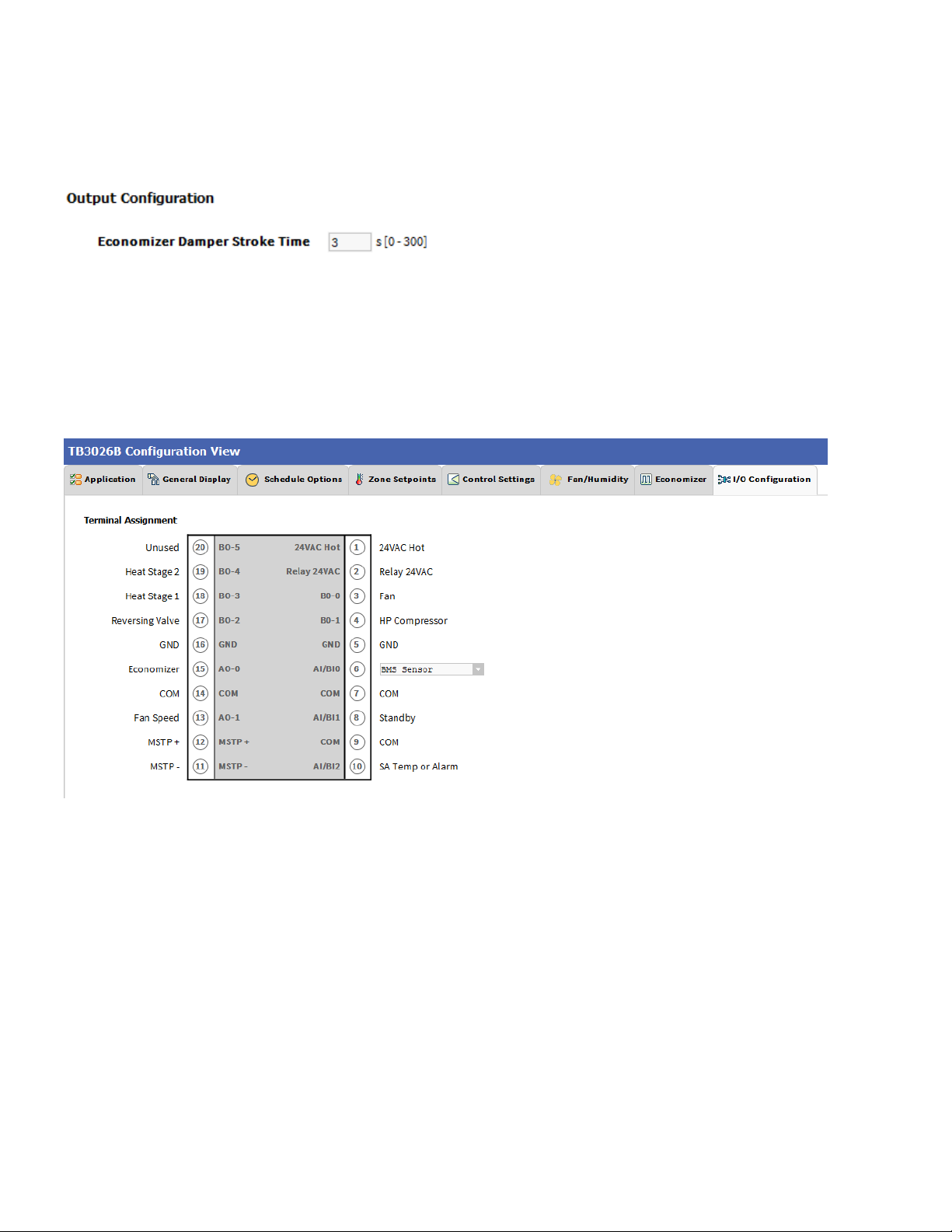
BACnet FF Controller
Figure 62: Terminal Assignment View (Water Source Heat Pump)
Output Configuration
When a user assigns the outputs, ‘Economizer Open’ and
‘Economizer Close’ to BO-4 and BO-5 respectively,
‘Economizer Damper Stroke Time’ can be mentioned in the
field ‘Output Configuration’. The default value is 3 seconds.
When ‘Output Stage’ is selected as ‘One Compressor Stage/Two Aux Heat Stages’, the ‘Terminal Assignment’ view
changes as follows:
66 31-00121—02
Page 69

Two Pipe Fan Coil Unit
BACnet FF Controller
Figure 63: Two Pipe Fan Coil Unit Window
Fan Speeds
A user can select Two types of ‘Fan Speeds’ when the
output stage is configured as ‘One Compressor Stage and
One Aux Heat Stage’.
1. Single Speed Fan
2. Three Speed Fan
31-00121—02 67
Page 70

BACnet FF Controller
Auxiliary Heat
A user can select heating stages from the following
options:
No Stage Aux Heat: If auxiliary heating is not required in
the system, select this option.
Single Stage Aux Heat: For single auxiliary heating stage,
select this option.
Note:
The Auxilliary heat can be selected as ‘No Stage Aux
Heat’ or ‘Single Stage Aux Heat’ only when Three
Speed Fan is configured.
Valve Actuator
Valve actuator can be configured as ‘Two-Position’ or
‘Floating/Analog’ based on application.
Note:
The valve actuator can be selected as ‘Two-Position’ or
‘Floating/Analog’ only when ‘Three Speed Fan’ is
configured.
Input Configuration
Input Configuration can be configured as ‘Remote Space
Temp Sensor’ or ‘Door Switch’ or ‘Water Temperature
Sensor’ based on application.
68 31-00121—02
Page 71

BACnet FF Controller
General Display
Click ‘General Display’ to view the general display
settings. The following parameters are used to configure
the controller’s display settings.
1. Engineering Units
2. Time Functions
3. Display
4. Contractor Access Codes
Figure 64: General Display Screen (Two Pipe Fan Coil Unit)
Engineering Units
Application Unit: The application units contain two
options to change the controller’s units. By default, the
controller’s application units are set to ‘English’. Application
Unit can be changed to ‘English’ or ‘Metric’.
31-00121—02 69
Page 72

BACnet FF Controller
Time Function
Clock Format: A user can select a clock format as
12-hour format or 24-hour format.
Display
This feature allows a user to select the Display settings.
Outside Air Temp: A user has an option to hide/show an
outside air temperature.
Clock Adjustment: This option allows a user to
enable/disable the clock adjustment on the controller
display.
Keypad Lockout: This option allows a user to lock/unlock
the clock adjustment.
When an option, ‘Temperature Settings Only’ is selected, a
user can only set the temperature through keypad.
Backlight: A user can keep the backlight always on or set
to delayed off through this option.
Daylight Savings Time: This feature enables to select the
Daylight Savings Time settings. By default, Daylight
Savings Time is set to ‘Disabled’. Daylight Savings Time
can be changed to ‘Pre-2007’ or ‘Post-2007’.
Contractor Access Codes
An access to the controller can be restricted with the help
of Access Codes.
Field Service Pin and Installer Service Pin can be set.
These codes should be enabled to restrict an access to the
controller.
Note:
A user can set only numerical PIN code for ‘Field
Service Pin’ and ‘Installer Service Pin’. PIN codes
should be set within 0000 – 9999. The following Error
Window pops up if this field is left blank after selecting.
70 31-00121—02
Page 73

Schedule Options
‘Schedule’ tab displays Schedule options.
The following parameters are used to configure the
schedule options (i.e. Occupancy Configuration and
Bypass and Standby)
BACnet FF Controller
Figure 65: Schedule Options Screen (Two Pipe Fan Coil Unit)
Occupancy Configuration
Schedule Model: A user can set the device’s schedule
model as;
1. Setpoint Mode or
2. Occupancy Mode
Setpoint Mode: In setpoint mode, the controller logically
emulates residential thermostats. The space temperature
is controlled to "SP Mode Cooling SP" and "SP Mode
Heating SP". Each schedule period consists of a start time,
a heating setpoint, and a cooling setpoint.
Occupancy Mode: By default, ‘Schedule Model’ is in
‘Occupancy Mode’. The system will be switched to
‘Occupied Mode’ when the occupancy sensor detects
occupancy. Occupied Mode allows a user to configure
‘Comm Fails Occupied’, ‘System Block’ & ‘Internal
Schedule’ settings.
If a user selects ‘Setpoint Mode’ from the available
‘Schedule Model’, the fields for ‘Comm Fails Occupied’
and ‘System Block’ settings become disabled.
31-00121—02 71
Page 74

BACnet FF Controller
Comm Fails Occupied: It allows a user to switch the
system in Occupied Mode in case of MS/TP
communication failure. If the MS/TP communication fails,
the system enters into Occupied Mode when this option is
selected as ‘Enable’, otherwise the system remains in its
current state when this option is selected as ‘Disable’.
System Block: The System Block is hidden when the
schedule model is in ‘Setpoint Mode’. When the schedule
model is in ‘Occupancy Mode’, it allows a user to switch
between the available options. Selecting “Show
Unoccupied/Off” places the controller in unoccupied state.
Internal schedule: It can be configured in both Occupancy
Mode & Setpoint Mode. By default, ‘Internal Schedule’ is
‘Disable’.
If the internal schedule is ‘Disable’, a user can adjust the
setpoint (within setpoint limits).
Display Settings
When a user selects, ‘Two Periods’ or ‘Four Periods’
options an additional ‘Display Settings’ appears as follows:
Bypass and Standby
Bypass Time: In the Unoccupied state, it forces the
controller into the occupied state for up to 4 hours (default
value). The override time limit is adjustable from a
minimum of 0.2 hours to a maximum of 9.5 hours.
Standby Delay: In Occupied Mode, if any window or door
is opened and closed with no motion detected after the
time mentioned for the Standby Delay, the room status
switches to Standby state. The default value is 180
seconds.
Schedule Access: When a user selects ‘Edit’, it allows a
user to view and edit the schedule and when a user selects
‘View’, it allows a user to view the schedule. When a user
selects ‘None’, it will not allow a user to view or edit the
schedule.
Vacation Hold: It allows/denies a user to override the
scheduled setpoint from TB3026B display to “Vacation
Hold”.
Permanent Hold: It allows/denies a user to override the
scheduled setpoint from TB3026B display to “Permanent
Hold”.
72 31-00121—02
Page 75

BACnet FF Controller
Zone Setpoints
Zone Setpoints , allows a user to set the following
parameters as per the requirement:
1. Temperature Setpoints
2. Setpoint Limits
3. Standby Settings
4. Display Options
Figure 66: Zone Setpoints Screen (Occupancy Mode)
Temperature Setpoints
Occupied Setpoint: It is a setpoint in Occupied Mode.
Enter the value within the range of 45 ºF to 99 ºF. The
default value is 70ºF.
31-00121—02 73
Cooling Offset: In the Occupied state, the cooling setpoint
is calculated as cooling offset plus occupied setpoint. Enter
the value within the range of 0ΔºF to 12.1ΔºF. The default
value is 2 ΔºF.
Heating Offset: In the Occupied state, the heating setpoint
is calculated as heating offset minus occupied setpoint.
Enter the value within the range of 0ΔºF to 12.1ΔºF. The
default value is 1 ΔºF.
Unoccupied Heating Setpoint: It is a setpoint for Heating
in Unoccupied mode. Enter the value within the range of
45 ºF to 99 ºF. The default value is 55 ºF.
Unoccupied Cooling Setpoint: It is a setpoint for Cooling
in Unoccupied mode. Enter the value within the range of
45 ºF to 99 ºF. The default value is 85 ºF.
Page 76

BACnet FF Controller
Setpoint Limits
Setpoint High Limit: A user can enter a Setpoint High
Limit in Occupied Mode within the range of 45 ºF to 99 ºF.
The default value is 78ºF.
Setpoint Low Limit: A user can enter a Setpoint Low Limit
in Occupied Mode within the range of 45 ºF to 99 ºF. The
default value is 62ºF.
Note:
1. Unoccupied Cooling Setpoint should always be set
GREATER than Unoccupied Heating Setpoint.
Following Error window appears if Unoccupied
Cooling Setpoint is set lower than Unoccupied
Heating Setpoint.
2. Setpoint High Limit should always be set GREATER
than Setpoint Low Limit.
Following Error window appears if Setpoint High
Limit is set lower than Setpoint low Limit.
Standby Settings
Standby state is a power-saving function of Occupancy
mode. It occurs when the space is scheduled as Occupied,
but sensors detect (When the Standby input is active)
there are no humans in the space.
Standby Offset: In this case, the Standby Offset relaxes
the occupied setpoints. The value of the Standby Offset
[SO] can be set between a minimum of 0 ΔºF and a
maximum of 12.1 ΔºF degrees. The default value is 4 ΔºF.
Reverse Standby Input: It allows a user to configure two
types of inputs, ‘Normally Open (NO)’ and ‘Normally Close
(NC)’.
74 31-00121—02
Page 77

BACnet FF Controller
Display Options
Unoccupied Setpoints: It allows a user to either ‘Hide’ or
‘Show’ the unoccupied setpoint.
When a user selects Schedule Model under the ‘Schedule Options’ tab to ‘Setpoint Mode’, the ‘Zone Setpoints’
configuration window appears as follows:
Figure 67: Zone Setpoint Screen (Setpoint Mode)
31-00121—02 75
Page 78

BACnet FF Controller
Control Settings
‘Control Settings’ allows a user to configure following
settings:
1. Cooling PI Control
2. Heating PI Control
3. Aux Staged Heating
4. Two-Position Valves
5. FCU Configuration
Figure 68: Control Settings Screen (Two Pipe Fan Coil Unit)
Cooling PI Control
Proportional Constant K
within the range of 10 to 40. The default value is 20.
Integral Constant K
: A user can enter a value for Kp
p
: A user can enter a value for Ki
i
within the range of 0.50 to 2. The default value is 1.
OAT Lockout Setpoint: Cooling PI control will lockout
76 31-00121—02
when outside Temperature decreases below OAT
(Cooling) Lockout Setpoint. The default value is 55 ºF.
Page 79

BACnet FF Controller
Heating PI Control
Proportional Constant K
: A user can enter a value for Kp
p
within the range of 10 to 40. The default value is 20.
Integral Constant K
: A user can enter a value for Ki
i
within the range of 0.50 to 2. The default value is 1.
OAT Lockout Setpoint: Heating PI control will lockout
when outside Temperature increases above OAT (Heating)
Lockout Setpoint. The default value is 62 ºF.
Aux Staged Heating
A user can configure the Cycle Time & Minimum On/Off
Time when a ’Single Stage Auxiliary Heat’ is selected in
the application.
Cycle Time: The Cycle Time ranges from minimum of 8
minutes, and a maximum of 30 minutes. The default value
is 15 minutes.
Minimum On/Off Time: It is a minimum On/Off time for
the Auxiliary Heating. The default value is 3 minutes.
Two-Position Valves
Cycle Time: Two-Position Valve cycle time ranges from
minimum of 3 minutes, and a maximum of 30 minutes. The
default value is 15 minutes.
Minimum On Time: It is a minimum time for the
compressor to stay On.
Minimum Off Time
: It is a minimum time for the
compressor to stay Off.
Heating/Cooling Valve Control: Physical heating/cooling
valve control has three options
On Off: This option selects the opening and closing of
heating valve.
Analog To Binary: In this mode the valve is remains open
for Cycle Time.
Thermal valve: This option allows a user to select a
Thermal valve for Heating/Cooling Valve Control.
FCU Configuration
A user can configure the Water Temperature when
‘Floating/Analog’ valve actuator is selected in the
application.
31-00121—02 77
Water Temperature: The water temperature can be
monitored either by local or by remote entity (default
inactive, ‘Local Mode’).
Page 80

BACnet FF Controller
When ‘Fan Speeds’ is selected as ‘Three Speed Fan’, the ‘Control Settings’ view changes as follows:
When ‘Auxiliary Heat’ is selected as ‘No Stage Aux heat’, the ‘Control Settings’ view changes as follows:
78 31-00121—02
Page 81

BACnet FF Controller
When ‘Valve Actuator’ is selected as ‘Two-Position’, the ‘Control Settings’ view changes as follows:
31-00121—02 79
Page 82

BACnet FF Controller
Fan / Humidity
‘Fan / Humidity’ allows a user to configure the
following settings:
1. Fan Operation
2. Humidity Control
3. Filter Alarm
Figure 69: Fan/Humidity Screen (Two Pipe Fan Coil Unit)
Fan Operation
Fan Mode Control: During occupancy & Setpoint mode,
the fan operates based on the selected fan control modes.
Auto: When this option is selected, Fan cycles ON when:
1. Cooling or heating is selected or
2. During Unoccupied mode only when called to run
by cooling or heating demand.
On: When this option is selected the fan runs continuously
for ventilation.
80 31-00121—02
Page 83

BACnet FF Controller
When a user selects ‘Three Speed Fan’ in the
application, the ‘Fan Operation’ parameter appears as
follows:
Auto: When this option is selected, Fan cycles ON when:
1. Cooling or heating is selected or
2. During Unoccupied mode only when called to run
by cooling or heating demand.
On: When this option is selected the fan runs continuously
for ventilation.
On Cool/Auto Heat: When this option is selected the fan
runs continuously in cooling mode. In heating mode the fan
cycles on only when the heating signal calls for the fan to
run.
Local User Fan Control: This selection allows a user to
enable/disable the fan Control to local user.
Low Speed Heat/Cool Demand: This field allows a user
to set the Heating/Cooling demand limits for the Low
Speed Fan.
Medium Speed Heat/Cool Demand: This field allows a
user to set the Heating/Cooling demand limits for the
Medium Speed Fan.
High Speed Heat/Cool Demand: This field allows a user
to set the Heating/Cooling demand limits for the High
Speed Fan.
Humidity Control
Fan Circulation Cycle: When a user selects the ‘Enable’
option from Fan Circulation Cycle, it allows a user to edit
the Trigger Setpoint, Reset Deadband, and Fan On/Off
Cycle Time.
Trigger Setpoint & Reset Deadband: When sensed
humidity equals or exceeds humidity trigger setpoint, the
fan cycles ON/OFF at low speed until sensed humidity
drops below the trigger setpoint minus the reset deadband.
Fan On Cycle Time: This field allows a user to enter a
time for fan ON cycle when stratification and humidity
control is active. The default value is 300 seconds.
Fan Off Cycle Time: This field allows a user to enter a
time for fan OFF cycle when stratification and humidity
control is active. The default value is 1800 seconds.
Filter Alarm
31-00121—02 81
Runtime Hours: A filter alarm activates after the Runtime
Hours mentioned in this field. The default value is 3000
hours.
Page 84

BACnet FF Controller
I/O Configurations
Select I/O Configurations from Configuration
parameters. This configuration is used for Terminal
Assignment & Output Configuration.
Figure 70: I/O Configurations Screen (Two Pipe Fan Coil Unit)
Terminal Assignment
After completing the ‘Two Pipe Fan Coil Unit’ configuration,
selected inputs and outputs get automatically assigned to
the TB3026B controller’s input and output terminals. A user
can assign the outputs as ‘Heating/Cooling Valve Close’ &
‘Heating/Cooling Valve Open’ to BO-4 & BO-3 respectively.
Figure 71: Terminal Assignment View (Single Speed Fan)
82 31-00121—02
Page 85

BACnet FF Controller
Output Configuration
H/C Valve Stroke Time: This setting is available to
configure, when ‘Floating/ Analog’ ‘Valve Actuator is
selected.
When ‘Three Speed Fan’ is configured with ‘Single Stage Aux Heat’, the ‘Terminal Assignment’ view changes as
follows:
When ‘No Stage Aux Heat’ is configured with ‘Floating/Analog’ valve actuator, ‘Three Speed Fan’ and ‘Door
Switch’, the ‘Terminal Assignment’ view changes as follows:
31-00121—02 83
Page 86

BACnet FF Controller
When ‘No Stage Aux Heat’ is configured with ‘Two-Position’ valve actuator, ‘Three Speed Fan’ and ‘Water
Temperature Sensor’, the ‘Terminal Assignment’ view changes as follows:
When ‘Input Configuration is selected as ‘Remote Space Temp Sensor’ with ‘No Stage Aux Heat’, ‘Floating/Analog’
valve actuator and ‘Three Speed Fan’, the ‘Terminal Assignment’ view changes as follows:
84 31-00121—02
Page 87

BACnet FF Controller
Four Pipe Fan Coil Unit
Figure 72: Four Pipe Fan Coil Unit window
Fan Speeds
A user can select Two types of ‘Fan Speeds’ when the
output stage is configured as ‘One Compressor Stage and
One Aux Heat Stage’.
1. Single Speed Fan
2. Three Speed Fan
31-00121—02 85
Auxiliary Heat
A user can select heating stages from the following
options:
Page 88

BACnet FF Controller
Valve Actuator
Valve actuator can be configured as ‘Two-Position’ or
‘Floating’, or ‘Analog’ based on application.
Note:
The valve actuator can be selected as ‘Two-Position’ or
‘Analog’ only when ‘Three Speed Fan’ is configured.
Floating valve actuator can be configured only when
Single Speed Fan is configured.
Input Configuration
Input Configuration can be configured as ‘Motion Sensor’
or ‘Remote Space Temp Sensor’ based on application.
Economizer Output
Out of the two types of parameters, select ‘Analog Output’
if Floating valve actuator ’is used. Select ‘Floating Output’
when analog valve actuator is used.
Note:
Analog Type Economizer Output can be configured
when Single Speed Fan is configured’.
Floating Type Economizer Output can only be
configured if Three Speed Fan is configured’.
86 31-00121—02
Page 89

BACnet FF Controller
General Display
Click ‘General Display’ to view the general display
settings. The following parameters are used to configure
the controller’s display settings.
1. Engineering Units
2. Time Functions
3. Display
4. Contractor Access Codes
Figure 73: General Display Screen (Four Pipe Fan Coil Unit)
Engineering Units
Application Unit: The application units contain two
options to change the controller’s units. By default, the
controller’s application units are set to ‘English’. Application
Unit can be changed to ‘English’ or ‘Metric’.
31-00121—02 87
Page 90

BACnet FF Controller
Time Function
Clock Format: A user can select a clock format as
12-hour format or 24-hour format.
Display
This feature allows a user to select the Display settings.
Outside Air Temp: A user has an option to hide/show an
outside air temperature.
Clock Adjustment: This option allows a user to
enable/disable the clock adjustment on the controller
display.
Keypad Lockout: This option allows a user to lock/unlock
the clock adjustment.
When an option, ‘Temperature Settings Only’ is selected, a
user can only set the temperature through keypad.
Backlight: A user can keep the backlight always on or set
to delayed off through this option.
Daylight Savings Time: This feature enables to select the
Daylight Savings Time settings. By default, Daylight
Savings Time is set to ‘Disabled’. Daylight Savings Time
can be changed to ‘Pre-2007’ or ‘Post-2007’.
Contractor Access Codes
An access to the controller can be restricted with the help
of Access Codes.
Field Service Pin and Installer Service Pin can be set.
These codes should be enabled to restrict an access to the
controller.
Note:
A user can set only numerical PIN code for ‘Field
Service Pin’ and ‘Installer Service Pin’. PIN codes
should be set within 0000 – 9999. The following Error
Window pops up if this field is left blank after selecting.
88 31-00121—02
Page 91

Schedule Options
‘Schedule’ tab displays Schedule options.
The following parameters are used to configure the
schedule options (i.e. Occupancy Configuration and
Bypass and Standby)
BACnet FF Controller
Figure 74: Schedule Options Screen (Four Pipe Fan Coil Unit)
Occupancy Configuration
Schedule Model: A user can set the device’s schedule
model as;
1. Setpoint Mode or
2. Occupancy Mode
Setpoint Mode: In setpoint mode, the controller logically
emulates residential thermostats. The space temperature
is controlled to "SP Mode Cooling SP" and "SP Mode
Heating SP". Each schedule period consists of a start time,
a heating setpoint, and a cooling setpoint.
Occupancy Mode: By default, ‘Schedule Model’ is in
‘Occupancy Mode’. The system will be switched to
‘Occupied Mode’ when the occupancy sensor detects
occupancy. Occupied Mode allows a user to configure
‘Comm Fails Occupied’, ‘System Block’ & ‘Internal
Schedule’ settings.
If a user selects ‘Setpoint Mode’ from the available
‘Schedule Model’, the fields for ‘Comm Fails Occupied’
and ‘System Block’ settings become disabled.
31-00121—02 89
Page 92

BACnet FF Controller
Comm Fails Occupied: It allows a user to switch the
system in Occupied Mode in case of MS/TP
communication failure. If the MS/TP communication fails,
the system enters into Occupied Mode when this option is
selected as ‘Enable’, otherwise the system remains in its
current state when this option is selected as ‘Disable’.
Note:
When Application 8 or 9 is selected, the ‘Comm Fails
Occupied’ will be selected as ‘Enable’ by default and
does not allow user to edit this field.
Vacation Hold: It allows/denies a user to override the
scheduled setpoint from TB3026B display to “Vacation
Hold”.
Permanent Hold: It allows/denies a user to override the
scheduled setpoint from TB3026B display to “Permanent
Hold”.
Bypass and Standby
System Block: The System Block is hidden when the
schedule model is in ‘Setpoint Mode’. When the schedule
model is in ‘Occupancy Mode’, it allows a user to switch
between the available options. Selecting “Show
Unoccupied/Off” places the controller in unoccupied state.
Internal schedule: It can be configured in both Occupancy
Mode & Setpoint Mode. By default, ‘Internal Schedule’ is
‘Disable’.
If the internal schedule is ‘Disable’, a user can adjust the
setpoint (within setpoint limits).
Display Settings
When a user selects, ‘Two Periods’ or ‘Four Periods’
options an additional ‘Display Settings’ appears as follows:
Schedule Access: When a user selects ‘Edit’, it allows a
user to view and edit the schedule and when a user selects
‘View’, it allows a user to view the schedule. When a user
selects ‘None’, it will not allow a user to view or edit the
schedule.
Bypass Time: In the Unoccupied state, it forces the
controller into the occupied state for up to 4 hours (default
value). The override time limit is adjustable from a
minimum of 0.2 hours to a maximum of 9.5 hours.
Standby Delay: In Occupied Mode, if any window or door
is opened and closed with no motion detected after the
time mentioned for the Standby Delay, the room status
switches to Standby state. The default value is 180
seconds.
90 31-00121—02
Page 93

BACnet FF Controller
Zone Setpoints
Zone Setpoints , allows a user to set the following
parameters as per the requirement:
1. Temperature Setpoints
2. Setpoint Limits
3. Standby Settings
4. Display Options
Figure 75: Zone Setpoints Screen (Occupancy Mode)
Temperature Setpoints
Occupied Setpoint: It is a setpoint in Occupied Mode.
Enter the value within the range of 45 ºF to 99 ºF. The
default value is 70ºF.
Cooling Offset: In the Occupied state, the cooling setpoint
is calculated as cooling offset plus occupied setpoint. Enter
31-00121—02 91
the value within the range of 0ΔºF to 12.1ΔºF. The default
value is 2 ΔºF.
Heating Offset: In the Occupied state, the heating setpoint
is calculated as heating offset minus occupied setpoint.
Enter the value within the range of 0ΔºF to 12.1ΔºF. The
default value is 1 ΔºF.
Unoccupied Heating Setpoint: It is a setpoint for Heating
in Unoccupied mode. Enter the value within the range of
45 ºF to 99 ºF. The default value is 55 ºF.
Unoccupied Cooling Setpoint: It is a setpoint for Cooling
in Unoccupied mode. Enter the value within the range of
45 ºF to 99 ºF. The default value is 85 ºF.
Page 94

BACnet FF Controller
Setpoint Limits
Setpoint High Limit: A user can enter a Setpoint High
Limit in Occupied Mode within the range of 45 ºF to 99 ºF.
The default value is 78ºF.
Setpoint Low Limit: A user can enter a Setpoint Low Limit
in Occupied Mode within the range of 45 ºF to 99 ºF. The
default value is 62ºF.
Note:
1. Unoccupied Cooling Setpoint should always be set
GREATER than Unoccupied Heating Setpoint.
Following Error window appears if Unoccupied
Cooling Setpoint is set lower than Unoccupied
Heating Setpoint.
2. Setpoint High Limit should always be set GREATER
than Setpoint Low Limit.
Following Error window appears if Setpoint High
Limit is set lower than Setpoint low Limit.
Standby Settings
Standby state is a power-saving function of Occupancy
mode. It occurs when the space is scheduled as Occupied,
but sensors detect (When the Standby input is active)
there are no humans in the space.
Standby Offset: In this case, the Standby Offset relaxes
the occupied setpoints. The value of the Standby Offset
[SO] can be set between a minimum of 0ΔºF and a
maximum of 12.1ΔºF degrees. The default value is 4 ΔºF.
Reverse Standby Input: It allows a user to configure two
types of inputs, ‘Normally Open (NO)’ and ‘Normally Close
(NC)’.
92 31-00121—02
Page 95

BACnet FF Controller
Display Options
Unoccupied Setpoints: It allows a user to either ‘Hide’ or
‘Show’ the unoccupied setpoint.
When a user selects Schedule Model under the ‘Schedule Options’ tab to ‘Setpoint Mode’, the ‘Zone Setpoints’
configuration window appears as follows:
Figure 76: Zone Setpoint Wizard Screen (Setpoint Mode)
31-00121—02 93
Page 96

BACnet FF Controller
Control Settings
‘Control Settings’ allows a user to configure following
settings:
1. Cooling PI Control
2. Heating PI Control
3. Two-Position Valves
Figure 77: Control Settings Screen (Four Pipe Fan Coil Unit)
Cooling PI Control
Proportional Constant K
within the range of 10 to 40. The default value is 20.
Integral Constant K
within the range of 0.50 to 2. The default value is 1.
OAT Lockout Setpoint: Cooling PI control will lockout
when outside Temperature decreases below OAT
(Cooling) Lockout Setpoint. The default value is 55 ºF.
: A user can enter a value for Kp
p
: A user can enter a value for Ki
i
Heating PI Control
Proportional Constant K
: A user can enter a value for Kp
p
within the range of 10 to 40. The default value is 20.
Integral Constant K
: A user can enter a value for Ki
i
within the range of 0.50 to 2. The default value is 1.
OAT Lockout Setpoint: Heating PI control will lockout
when outside Temperature increases above OAT (Heating)
Lockout Setpoint. The default value is 62 ºF.
94 31-00121—02
Page 97

BACnet FF Controller
Two-Position Valves
Cycle Time: Two-Position Valve cycle time ranges from
minimum of 3 minutes, and a maximum of 30 minutes. The
default value is 15 minutes.
Minimum On Time: It is a minimum time for the
compressor to stay On.
Minimum Off Time: It is a minimum time for the
compressor to stay Off.
Heating/Cooling Valve Control: Physical heating/cooling
valve control has three options
On Off: This option selects the opening and closing of
Heating valve.
Analog To Binary: In this mode the valve is remains open
for Cycle Time.
Thermal valve: This option allows a user to select a
Thermal valve for Heating/Cooling Valve Control.
When ‘Auxiliary heat’ is configured as ‘Single Stage Aux Heat’, the ‘Control Settings’ view changes as follows:
31-00121—02 95
Page 98

BACnet FF Controller
Aux Staged Heating
A user can configure the Cycle Time & Minimum On/Off
Time when a ’Single Stage Auxiliary Heat’ is selected in
the application.
Cycle Time: The Cycle Time ranges from minimum of 8
minutes, and a maximum of 30 minutes. The default value
is 15 minutes.
Minimum On/Off Time: It is a minimum On/Off time for
the Auxiliary Heating. The default value is 3 minutes.
When ‘Analog/Floating’ valve actuator is configured, the ‘Control Settings’ view changes as follows:
96 31-00121—02
Page 99

BACnet FF Controller
Fan / Humidity
‘Fan / Humidity’ allows a user to configure the
following settings:
1. Fan Operation
2. Humidity Control
3. Filter Alarm
Figure 78: Fan/Humidity Screen (Four Pipe Fan Coil Unit)
31-00121—02 97
Page 100

BACnet FF Controller
Fan Operation
Fan Mode Control: During occupancy & Setpoint mode,
the fan operates based on the selected fan control modes.
Auto: When this option is selected, Fan cycles ON when:
1. Cooling or heating is selected or
2. During Unoccupied mode only when called to run
by cooling or heating demand.
On: When this option is selected the fan runs continuously
for ventilation.
On Cool/Auto Heat: When this option is selected the fan
runs continuously in cooling mode. In heating mode the fan
cycles on only when the heating signal calls for the fan to
run.
Fan OFF Selection: This selection allows a user to
enable/disable the selection to OFF the fan on the LCD of
the controller.
Local User Fan Control: This selection allows a user to
enable/disable the fan Control to local user.
Low Speed Heat/Cool Demand: This field allows a user
to set the Heating/Cooling demand limits for the Low
Speed Fan.
Medium Speed Heat/Cool Demand: This field allows a
user to set the Heating/Cooling demand limits for the
Medium Speed Fan.
High Speed Heat/Cool Demand: This field allows a user
to set the Heating/Cooling demand limits for the High
Speed Fan.
When a user selects ‘Single Speed Fan’ in the
application, the ‘Fan Operation’ parameter appears as
follows:
Auto: When this option is selected, Fan cycles ON when:
1. Cooling or heating is selected or
2. During Unoccupied mode only when called to run
by cooling or heating demand.
On: When this option is selected the fan runs continuously
for ventilation.
On Cool/Auto Heat: When this option is selected the fan
runs continuously in cooling mode. In heating mode the fan
cycles on only when the heating signal calls for the fan to
run.
98 31-00121—02
 Loading...