

TotalZone® Add-A-Zone™(TAZ-4)
Zone Control Panel
INSTALLATION INSTRUCTIONS
APPLICATION
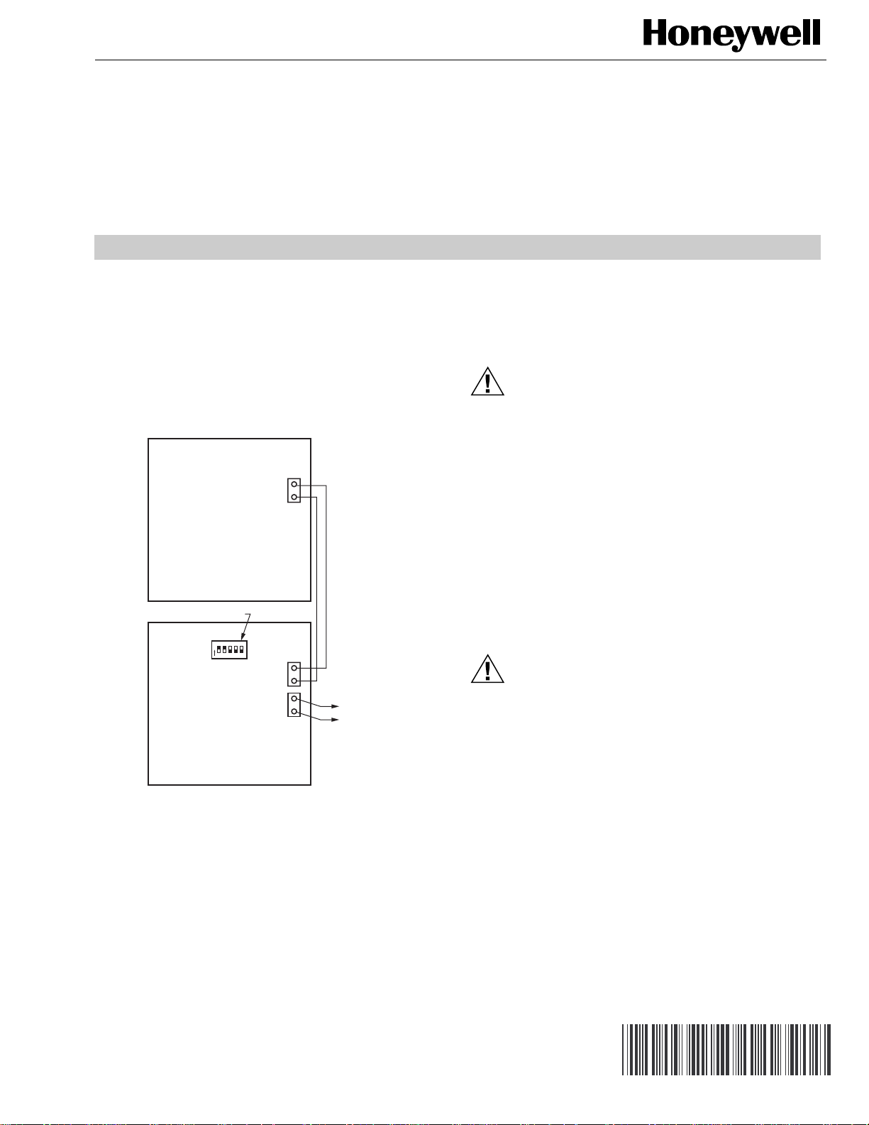
The TAZ-4 is a zone panel used to add zones to the TZ-4. See
Fig. 1. The TZ-4 provides up to four zones. Each TAZ-4 can
add up to four additional zones for a total of 32 zones. The
TAZ-4 is also compatible with the TZ-3, Rev 4.2.2, zone
control panel and with the TAZ-1, TAZ-2 and TAZ-3, Rev 4,
Add-A-Zone panels.
AZ1
AZ2
TotalZone Panel
DIP-SWITCHES
O
N
54321
TotalZone
Add-A-Zone Panel
AZ1
AZ2
AZ1
AZ2
TO NEXT
ADD-A-ZONE
PANEL
3. Installer must be a trained, experienced service technician.
4. After installation is complete, check out product operation as provided in these instructions.
5. Follow local codes for installation and application.
CAUTION
Voltage Hazard.
Can cause electrical shock or equipment damage.
Disconnect power before beginning installation.
Location
Select a location for the TAZ-4 as close as possible to the
Total Zone panel.
Mounting
Mount the TotalZone Add-A-Zone Panel as close as possible
to the TotalZone Panel. See Fig. 1.
WIRING
CAUTION
Electrical Interference Hazard.
Running cable near line voltage can interfere with
panel operation.
Run cable connecting AZ terminals at least
12 in. from line voltage wiring.
M20362
Fig. 1. TAZ-4 Zone Control Panel.
INSTALLATION
When Installing this Product . . .
1. Read these instructions carefully. Failure to follow them
could damage the product or cause a hazardous condition.
2. Check the rating given in the instructions and on the
product to make sure the product is suitable for your
application.
® U.S. Registered Trademark
Copyright © 2002 Honeywell • All Rights Reserved
IMPORTANT
Be sure AZ1 and AZ2 wires do not cross and are a
minimum of 12 in. from any line voltage wiring. If not
possible, use shielded cable for AZ1 and AZ2 wires.
NOTE: Only two wires are required to connect the TAZ-4
panels to the main TZ-4 panel. Each TAZ-4 is wired
in a daisy chain or parallel to each other, connecting
the AZ1 and AZ2 terminals between panels.
Connect the AZ1 and AZ2 terminals on both panels using
standard 18-gauge thermostat wire:
1. Connect AZ1 on the TotalZone panel to AZ1 on the
Add-A-Zone panel.
2. Connect AZ2 on the TotalZone panel to AZ2 on the AddA-Zone panel.
69-1366-2
TOTALZONE® ADD-A-ZONE™(TAZ-4) ZONE CONTROL PANEL
3. Connect a 24V, 40 VA transformer to terminals R and C.
R is Hot and C is 24 Vac (Common). See
Fig. 2.
4. If there are five to ten ARD or ZD dampers connected to
the TAZ-4, wire an additional 40 VA transformer to T1
and T2. See Fig. 2.
5. Connect damper and thermostat wiring as shown
in Fig. 2.
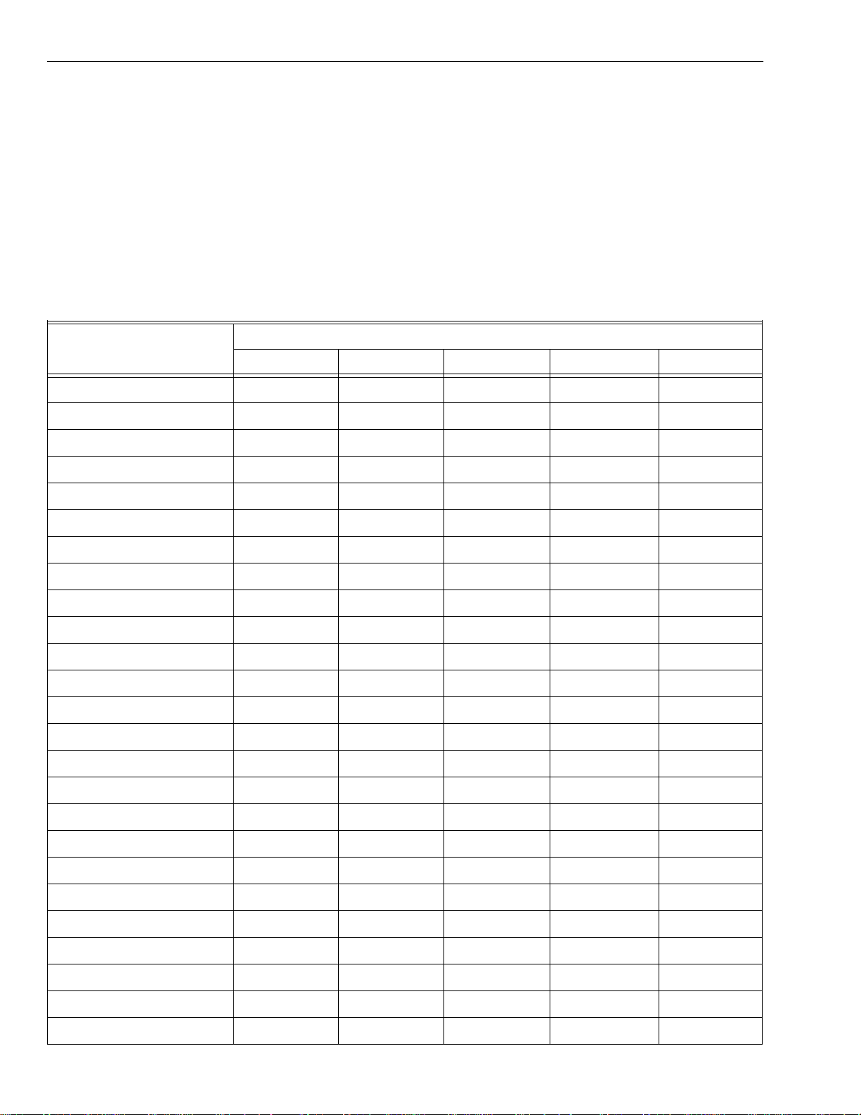
Table 1. DIP Switch Settings.
Zones
5-8 001 01
6-9 001 10
7-10 0 0 1 1 1
8-11 0 1 0 0 0
9-12 0 1 0 0 1
Switch 1 Switch 2 Switch 3 Switch 4 Switch 5
SETUP
Each TAZ-4 panel has a set of five DIP switches. When using
a TZ-4 and one TAZ-4, set DIP switches 1, 2, and 4 to off and
switches 3 and 5 to on. Refer to Table 1 for other panel
configurations. Identify the zones that are controlled by the
TAZ-4 panel and set the DIP switches accordingly.
If the TAZ-4 is connected to a TZ-3 zone control panel, set
DIP switches 1, 2, and 4 to off, and switches 3 and 5 to on.
Set the switches on additional TAZ-1, TAZ-2, and TAZ-3, or
TAZ-4 panels to control the zones they are wired to; but be
careful that there is no duplication of zone numbers. See
Table 1.
Switch Positions
10-13 010 10
11-14 01011
12-15 011 00
13-16 011 01
14-17 011 10
15-18 011 11
16-19 100 00
17-20 100 01
18-21 100 10
19-22 100 11
20-23 101 00
21-24 101 01
22-25 101 10
23-26 101 11
24-27 110 00
25-28 110 01
26-29 110 10
27-30 110 11
28-31 111 00
29-32 111 01
69-1366-2 2

TOTALZONE® ADD-A-ZONE™(TAZ-4) ZONE CONTROL PANEL
)
ZONE
N1ZONE
COMM ZONE
N
N3ZONE
2
N
4
DIP SWITCH SETTINGS 1 = ON 0 = OFF
12345 N
0 0 1 0 1 ZONES 5 6 7 8
0 0 1 1 0 ZONES 6 7 8 9
0 0 1 1 1 ZONES 7 8 9 10
0 1 0 0 0 ZONES 8 9 10 11
0 1 0 0 1 ZONES 9 10 11 12
0 1 0 1 0 ZONES 10 11 12 13
0 1 0 1 1 ZONES 11 12 13 14
0 1 1 0 0 ZONES 12 13 14 15
0 1 1 0 1 ZONES 13 14 15 16
0 1 1 1 0 ZONES 14 15 16 17
0 1 1 1 1 ZONES 15 16 17 18
1 0 0 0 0 ZONES 16 17 18 19
1 0 0 0 1 ZONES 17 18 19 20
1 0 0 1 0 ZONES 18 19 20 21
1 0 0 1 1 ZONES 19 20 21 22
1 0 1 0 0 ZONES 20 21 22 23
1 0 1 0 1 ZONES 21 22 23 24
1 0 1 1 0 ZONES 22 23 24 25
1 0 1 1 1 ZONES 23 24 25 26
1 1 0 0 0 ZONES 24 25 26 27
1 1 0 0 1 ZONES 25 26 27 28
1 1 0 1 0 ZONES 26 27 28 29
1 1 0 1 1 ZONES 27 28 29 30
1 1 1 0 0 ZONES 28 29 30 31
1 1 1 0 1 ZONES 29 30 31 32
ZONE 1
Thermostat Damper
W1/
E
Y1
RC
1
Y1 W3/
2
W3/
AUX
O/B Y2GW2M6M4M1
L
1
W2W1/ERCY2GLO/B Y1 W3/
AUX
Zone 1 Thermostat
1N2N3N4
ZONE 2
Thermostat Damper
W1/
ERC
W3/
O/B Y2GW2
AUXY1
W2W1/ERCY2GLO/B Y1 W3/
AUX
Zone 2 Thermostat
DIP SWITCH
O
N
1
2 3 4 5
2
M6 M4 M1
L
ZONE LEDs
ON Damper open or opening
OFF Damper closed or closing
MOMENTARY PUSH BUTTON
Boot — Clears microprocessor
ZONE 3
Thermostat Damper
W1/
O/B Y2GW2
ERC
1
Zone 3 Thermostat
BOOT
2
W3/
M6 M4 M1
AUXY1
L
W2W1/ERCY2GLO/B Y1 W3/
AUX
ZONE 4
Thermostat Damper
W1/
O/B Y2GW2
ERC
1
W2W1/ERCY2GLO/B
Zone 4 Thermostat
W3/
AUXY1
AUX
AZ1
AZ2
AZ1
AZ2
PANEL
XFRM
R
C
T1
T2
DAMPER
XFRM
2
M6 M4 M1
L
Add-A-Zone
or TZ Panel(s
Add-A-Zone
Panel(s)
24VAC, 40VA
Transformer
R
C
CR
24VAC, 40VA
Transformer
(Required if
more than
four dampers)
456Z
123X
Power-open
Power-closed
(Opposed Blade
Damper Motors)
Power-closed
Spring-open
(Model ZBD, ZDS,
or ARD-PC)
ZONE DAMPER MOTORS
M1 - common
M4 - power open
M6 - power closed
Power-open
Spring-closed
(Model ARD-PO)
1 “C” terminal connection is not required on battery powered, power stealing, or some electromechanical thermostats.
2 Leave jumper disconnected for “B” type or conventional thermostats. Connect jumper for “O” type thermostats.
This diagram shows the typical thermostat and damper motor connections. For specific wiring
for other thermostats and damper motors, refer to the Installation Instructions.
Minneapolis, MN 55422
www.honeywell.com/yourhome
Fig. 2. Wiring Add-A-Zone panel.
Power-open
Spring-closed
(Model ARD-PO)
M20363
3 69-1366-2

TOTALZONE® ADD-A-ZONE™(TAZ-4) ZONE CONTROL PANEL
Printed in U.S.A. on recycled
paper containing at least 10%
post-consumer paper fibers.
TECHNICAL SUPPORT
For Internet access: www.trolatemp.com or
www.honeywell.com/yourhome/zoning/zoning_home.htm
Call 1-800-828-8367 for zoning technical support line.
To download Zoning literature: http://hbctechlit.honeywell.com
Automation and Control Solutions
Honeywell Honeywell Limited-Honeywell Limitée
1985 Douglas Drive North 35 Dynamic Drive
Golden Valley, MN 55422 Scarborough, Ontario
69-1366-2 G.H. Rev. 02-02 www.honeywell.com/yourhome
M1V 4Z9
 Loading...