

Honeywell TARS Installation Instructions Manual
Installation Instructions for the
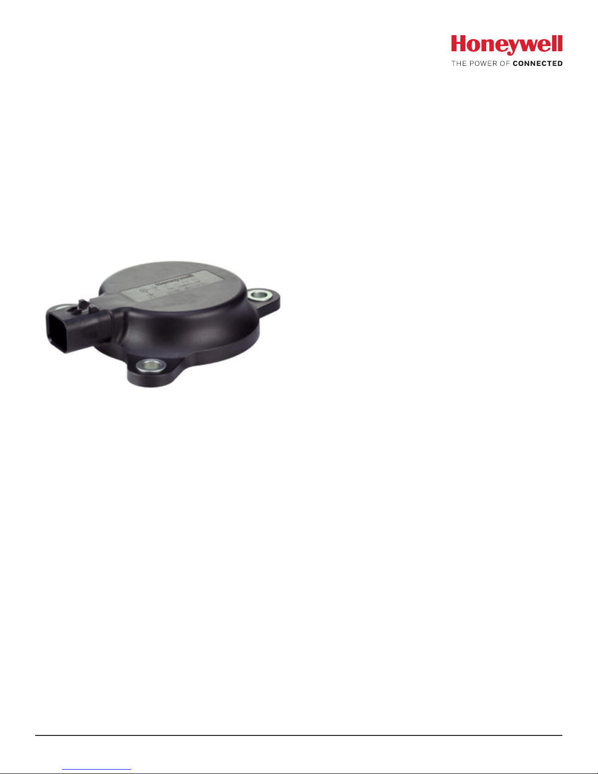
Transportation Attitude Reference Sensor
TARS Series
1.0 GENERAL INFORMATION
Honeywell’s Transportation Attitude Reference Sensor (TARS)
Interial Measurement Unit (IMU) is designed to provide motion
sensing through 6 degrees of freedom and reporting of
angular rate, acceleration, and inclination data through a CAN
J1939 interface. It is packaged for harsh environments and
demanding applications.
2.0 CALIBRATION
TARS-IMU devices are aligned to a flat surface and calibrated
on an aerospace-grade rate table providing consistency
between units and eliminating the customer’s need to calibrate
the IMU.
3.0 INSTALLATION
Mount the sensor using the three mounting holes and three
non-magnetic, stainless-steel socket head cap screws, M8 or
equivalent. Torque to 20 Nm ±2 Nm.
• Mating connector: AMPSEAL 16 Series, 776487-1 for 18-16
AWG conductors or 776524-1 for 20-18 AWG conductors
• Mounting direction: +Z
Issue A
32332897
Sensing and Internet of Things

Transportation Attitude Reference Sensor
ISSUE A
32332897
(TARS Series)
4.0 SPECIFICATIONS
Table 1. Sensor Specifications
Characteristic Min. Typ. Max. Unit
Gyroscope 3 axis performance
Angular rate range -245 – +245 deg/sec
Angular rate resolution – 7.8125 – mdps
In-run bias stability – 1 – mdps
Rate noise density – 0.004 – deg/sec/sqrt Hz
Offset (0 °C to 50 °C) -0.8 – +0.8 deg/sec
Offset (-40 °C to 85 °C) -1.6 – +1.6 deg/sec
Accelerometer 3 axis performance
Acceleration range -78.48 – +78.48 m/s
Acceleration resolution – 0.01 – m/s
In-run bias stability – 50 – mg
Acceleration noise density – 65 – mg/sqrt Hz
Offset (0 °C to 50 °C) – ±0.05 – m/s
Offset (-40 °C to 85 °C) – ±0.15 – m/s
Inclination (pitch and roll) performance
Range (2 axis x & y) -85 – +85 deg
Resolution – 0.058 – deg
Static inclination error
(0 °C to 50 °C)
Static inclination error
(-40 °C to 85 °C)
Translational acceleration error – ±0.5 – deg
Centripetal acceleration error – ±0.5 – deg
Settling time – 2000 mSec
– ±0.3 – deg
– ±0.9 – deg
2
2
2
2
Table 2. Electrical Characteristics • TARS-LCASS
Characteristic Min. Nominal Max. Unit
Supply voltage 4.5 5 5.5 V
Supply current – – 100 mA
Start-up time 500 – 2000 mSec
Short circuit protection CAN output shorted to power line and ground
Open circuit protection Single-line interruption and multiple-line interruption
Reset response Automatic after voltage drop
CAN output characteristics per SAE J1939
CAN Bus data rate – 250 – kBaud
Signal update rate – – 100 Hz
2 sensing.honeywell.com

Transportation Attitude Reference Sensor
ISSUE A
32332897
(TARS Series)
Table 3. Electrical Characteristics • TARS-HCASS
Characteristic Min. Nominal Max. Unit
Supply voltage 9 14/28 36 V
Supply current – – 100 mA
Reverse voltage – – -36 V
Overvoltage – – 36 V
Start-up time 500 – 2000 mSec
Short circuit protection CAN output shorted to power line and ground
Open circuit protection Single-line interruption and multiple-line interruption
Reset response Automatic after voltage drop
CAN output characteristics per SAE J1939
CAN Bus data rate – 250 – kBaud
Signal update rate – – 100 Hz
Table 4. Environmental Specifications
Characteristic Parameter
Operating temperature -40 °C to 85 °C [40 °F to 185 °F]
Storage temperature -40 °C to 105 °C [40 °F to 221 °F]
Random vibration
Mechanical shock 50 g 11 mS half-sine, 3 each direction, 18 total, pulse per MIL-STD-202, Method 213
Chemical compatibility
Moisture resistance per MIL-STD-202, Method 106 (10 cycles, 24 hours/cycle)
Thermal shock 250 cycles, -40 °C to 85 °C, 73 min dwells
Salt spray 5 % salt solution, 96 hours
Ingress protection IP67, IP69K (DIN40050-1993) with mating connector installed
RoHS Compliant
REACH Compliant
UV rating Enclosure material meets outdoor suitability requirements per UL746C F1 rating
8 hours per axis at 16.91 g RMS
per MIL-STD-202, Method 214, Test Condition I, Letter E
Diesel fuel, hydraulic oil, ethylene glycol, motor oil, brake fluid, urea nitrogen, liquid lime,
NPK fertilizer, ammonium hydroxide, alkaline degreaser, transmission oil, power steering
fluid, and axle oil
Table 5. EMC Specifications
Characteristic Stndard Test Level, Frequency
Radiated immunity ISO 11452-2 125 V/m, 400 MHz to 2.5 GHz
Bulk current injection ISO 11452-4: 2011 125 mA, 1 MHz to 400 MHz
Radiated emission ISO 13766 30 MHz to 1 GHz
Mutual coupling ISO 7637-3 Test pulse A, Test pulse B (-80 V, 80 V)
ESD direct contact discharge ISO 10605 ±8 kV
ESD air discharge ISO 10605 ±15 kV
Sensing and Internet of Things 3
 Loading...