

Honeywell TAM DATASHEET
Mechanical Thermostats
1
8
Technical data
Mechanical thermostats
Principal technical data
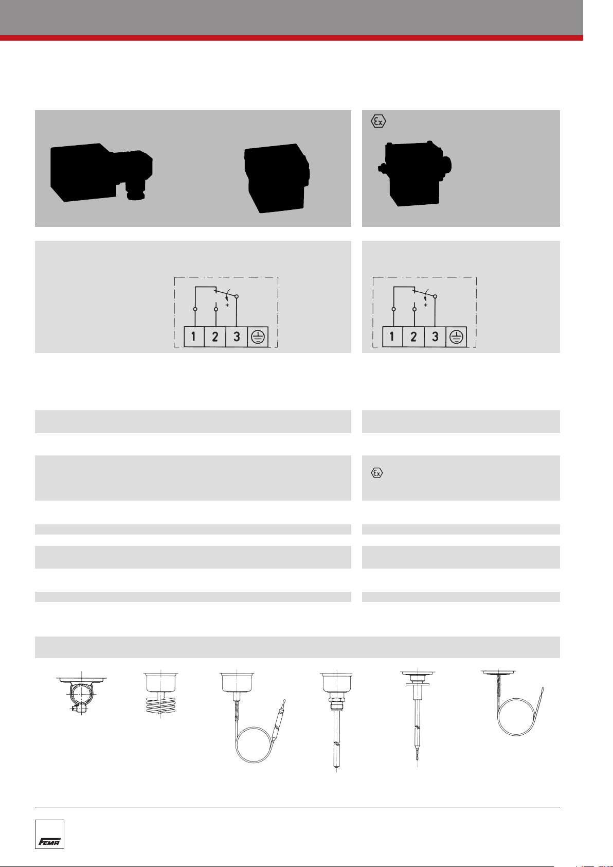
Standard version Terminal connection -version
…200 …300 …700
Switch housing
Switching function Floating change-over contact Floating changeover contact.
and connection drawing With rising pressure switching single-pole With rising pressure switching single-pole
(applies only to version from 3–1 to 3–2 from 3–1 to 3–2
with microswitch)
Switching capacity 8 A at 250 VAC 3 A at 250 VAC
(applies only to version 5 A at 250 VAC inductive 2 A at 250 VAC inductive
with microswitch) 8 A at 24 VDC 3 A at 24 VDC
Mounting position vertical or horizontal vertical
Degree of protection IP 54 (terminal connection IP 65) IP 65
(in vertical position)
Explosion protection – EEx de IIC T6
Code – II 2 G D EEx de IIC T6 IP65 T80° C
ype Examination –
EC T
Certificate Number
Electrical connection
Cable entr
Ambient temperature -15 to +70 °C -15 to +60 °C
Switching point Adjustable with spindle. Adjustable with spindle after
Switching differential Adjustable or not adjustable Not adjustable
Medium temperatur
Vibration strength No significant deviations up to 4 g.
Isolation values Overvoltage category III, contamination class 3, reference surge voltage 4000 V.
Sensor systems
y
e
Diecast aluminIum GDAISi 12 Diecast aluminIum GDAISi 12
0.3 A at 250 VDC 0.03 A at 250 VDC
min. 10 mA, 12 VDC min. 2 mA, 24 VDC
preferably vertical
PTB 02 A
Plug connection to DIN 43650/ Terminal connection
Terminal connection
PG 11 / for ter
(see Product Summary)
Max. 70
At higher accelerations the switching differential is reduced slightly.
Use over 25 g is not per
Confor
minal connection M 16 x 1.5
C
C, briefly 85
°
mity to DIN VDE 0110 (01.89) is confir
°
mitted.
M 16 x 1.5
the terminal box lid is removed.
Max. 60 °C
med.
TEX 1121
Strap-on sensor
TKM
Room sensor
TRM
Capillary tube sensor
AM
T
Rod sensor
TX + R 1
Air duct sensor
TX + R 6
Frost protection sensor
FT
Mechanical Thermostats
Temperature monitoring
Temperature monitoring
n explosion-endangered areas
i
T
emperature switches with special equipment can also be used in
explosion risk area ≥ Zone 1 (21).
The following alternatives are possible:
1. Thermostats with pressure-proof encapsulated switching device,
degree of protection II 2 G/D EEx de IIC T6 IP65 T 80°C
The thermostat in pressure-proof encapsulation can be used directly in explosion risk areas ≥ Zone 1
(21). The maximum switching voltage, switching capacity and ambient temperature must be taken into
account and the rules for installation in the explosion risk area must be observed.
All thermostats may be equipped with explosion-proof switching devices. However, special circuits
and designs with an adjustable switching differential are not permitted.
2. Thermostats in EExi version
mostats in the standard version can be used in explosion risk areas ≥ Zone 1, if they are incor-
All ther
porated into an “intrinsically safe circuit”. Intrinsic safety is based on the principle that the control current circuit in the explosion risk area carries only a small quantity of energy which is not capable of
generating an ignitable spark.
Isolating amplifiers, e.g. type Ex 011, must be tested by the Physikalisch-Technische Bundesanstalt
(PTB) pursuant to ATEX 100 and approved for use in explosion risk areas. Isolating amplifiers must in
any event be installed outside the explosion risk area.
Thermostats which are intended for EEx-ia installations are equipped with blue terminals and cable
entries. In view of the low voltages and currents carried via the contacts of the microswitches, goldplated contacts are used in the EX-i version (additional function ZFT 513).
1
9
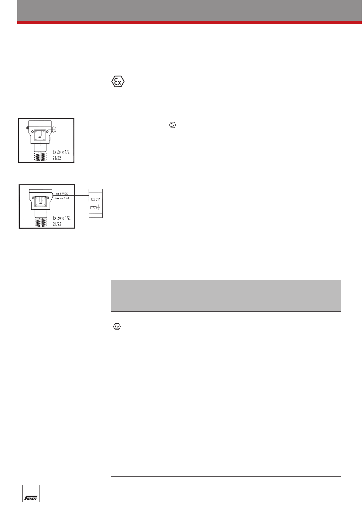
Temperature monitoring in Zone 1 (21) and 2 (22)
essure-proof encapsulated
Pr
Ex-de …
Explosion protection:
II 2 G/D EEx de IIC T6 IP 65 T80° C
ATEX approval for the
complete switching device
Thermostats with silver contact
Switching capacity:
max. 3 A, 250 V
min. 2 mA, 24 VDC
AC
Intrinsically safe
D …-513 +Ex 011
Explosion protection:
EEx-ia
ATEX approval for isolating amplifier
Ex 011
Thermostats with gold-plated
contacts, blue terminals and
blue cable entries.
Switching capacity:
Information for devices with additional function
ZF 513, ZF 574, ZF 576 to EN 50020:
i
= 10 VDC
U
i
= 20 mA
I
i
= 0 µH
L
i
= 0 pF
C
max. 100 mA, 24 VDC
min. 2 mA, 5 VDC
The thermostat can be installed
within the Ex-Zone.
The isolating amplifier must be installed
outside the Ex-Zone.
 Loading...