

Page 1
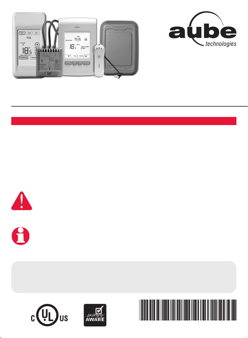
EConnect™ Wireless Thermostat Kit TA7210
With Equipment Interface Module
Installation guide for:
• Wireless equipment interface module
• EConnect™ wireless thermostat
• Wireless remote control
• Wireless outdoor air sensor
IMPORTANT INSTRUCTIONS
ELECTRICAL HAZARD
Can cause electrical shock or equipment damage. Disconnect power
before beginning installation.
Must be installed by a certified electrician. Read these instructions
carefully. Failure to follow these instructions can damage the product or cause a
hazardous condition.
System
Installation
Guide
Need Help?
For assistance with this product please visit www.aubetech.com,
or call Honeywell Customer Care toll-free at 1-800-831-2823.
69-2472EF-01
Page 2
Installation Guide
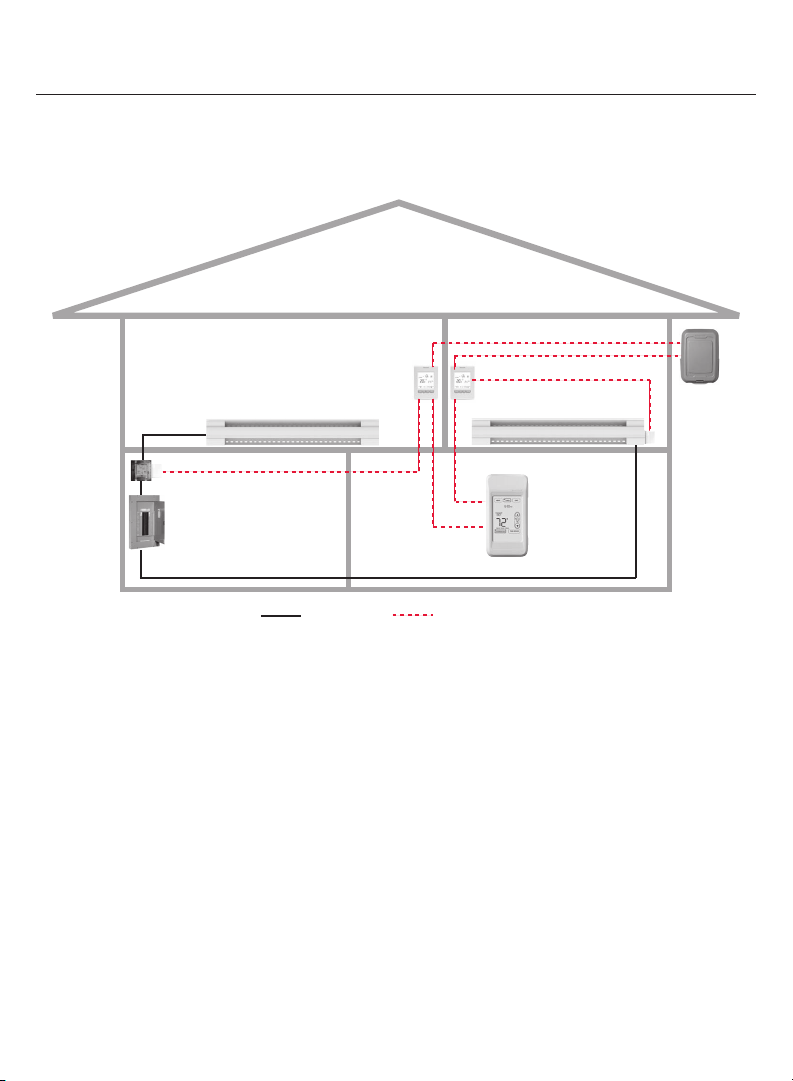
System installation at a glance
The equipment interface module (EIM) allows you to control a baseboard heater, a
convector or a fan-forced heater in a 120-volt, 208-volt or 240-volt application from a
EConnect™ wireless thermostat.
Thermostat
EIM in heater
Remote
control
Outdoor
air sensor
EIM in remote
junction box
Electrical
panel
Thermostat
Heater
Supply wires Wireless connection
Installation procedure
1 Install the equipment interface module (EIM) .......................................Pages 3 - 6
2 Install batteries in wireless devices ............................................................. Page 7
3 Link all devices to wireless network ...................................................Pages 7 - 10
4 Exit wireless setup .....................................................................................Page 11
5 Customize thermostat (installer setup) .............................................Pages 11 - 18
6 Mount thermostat and outdoor sensor ............................................Pages 19 - 20
For error codes, see page 20.
To verify the signal strength, see page 21.
To replace a wireless device, see pages 21-22.
For specifications and replacement parts, see page 23.
SAVE THESE INSTRUCTIONS
69-2472EF—01 2
Page 3
EConnect™ TA7210
1 Install the Equipment Interface Module (EIM)
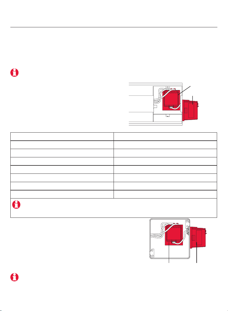
Determine the location
The equipment interface module (EIM) consists of a relay and an antenna. They can be
installed either in the wiring compartment of the baseboard heater or in a 4-11/16” square
junction box.
Install EIMs at a minimum distance of 2 feet (0.6 m) of each other. This minimum
distance still applies even if the EIMs are on opposite sides of a wall.
• Installing the EIM in a baseboard heater
You can install the EIM in the wiring
compartment of the baseboard heater if you
have any of the heaters listed in the following
table:
Manufacturer / brand Series
Cadet F
Global Commander CCB
King Electrical K, CB, KP, M
Marley 2500, BKOC, QMKC
Ouellet ODBA, ODI, ODIA, OFM, OPR
Stelpro CBB, N, SCA, SCAS
TPI 2900C, 2900S, 3700, 3900
The product has been tested for compatibility with the heaters listed above. If your heater is
not on the list, install the EIM on a 4-11/16" square junction box or replace your heater with
one listed.
• Installing the EIM in a 4-11/16" square
junction box
You can use a 4-11/16" square junction box in either
of the following conditions:
• You have a convector or fan-forced heater.
• You cannot install or do not wish to install the
EIM in the wiring compartment of the baseboard
heater.
The junction box can be installed anywhere in the house;
for example, near the main electrical panel.
Relay
Antenna
AntennaRelay
3 69-2472EF—01
Page 4
Installation Guide
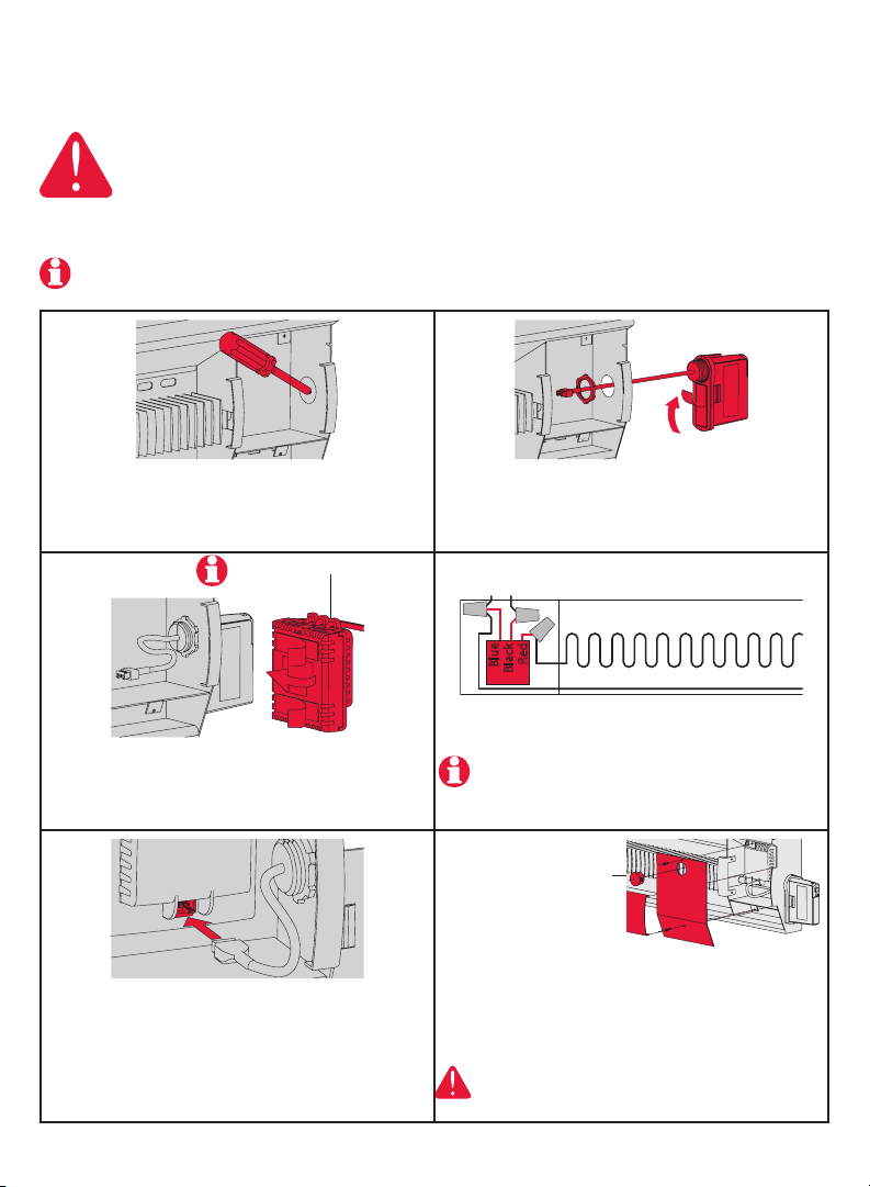
Installation in a baseboard heater
ELECTRICAL HAZARD
Can cause electrical shock or equipment damage. Disconnect AC power
before beginning installation.
Wiring must comply with local electrical codes. Use special CO/ALR solderless
connectors if supply wires are made of aluminum.
Disconnect the heater wires from the supply wires. If the heater has a built-in thermostat,
remove it.
1 Remove the knockout on the side of the heater.
Relay wires must be at the top
3 Clean the back panel inside the wiring
compartment where the relay will be installed. Peel
the adhesive backing off the relay and stick the
relay on the back panel.
5 Insert the antenna plug into the relay receptacle
until you hear a click.
2 Remove the locknut from the antenna and peel
off the adhesive backing. Feed the antenna cable
through the knockout and install the antenna vertically as shown. Put the locknut on and tighten.
N L : For 120V application
L2 L1 : For 240V application
Red
Blue
Black
4 Connect the heater wires and the supply wires to
the relay.
See page 6 if you are connecting more than one
heater.
Install plug if
applicable.
6 Put the heater cover back. (If a built-in
thermostat was removed, install one of the
supplied plugs to cover the hole on the existing
cover.) Apply power to the heater. Do not install
the antenna cover yet.
ELECTRICAL HAZARD
Can cause electrical shock. Install heater cover
plate before applying power.
69-2472EF—01 4
Page 5
Installation in a 4-11/16" square junction box
ELECTRICAL HAZARD
Can cause electrical shock or equipment damage. Disconnect AC power
before beginning installation.
Wiring must comply with local electrical codes. Use special CO/ALR solderless
connectors if supply wires are made of aluminum.
EConnect™ TA7210
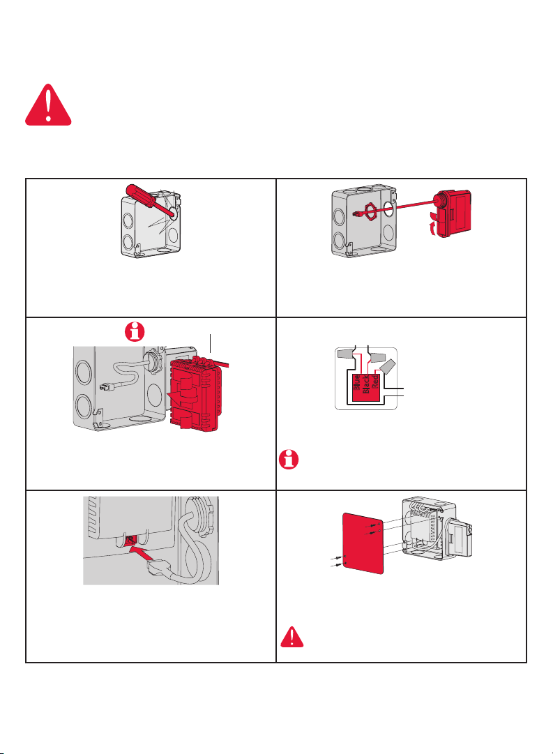
1 Mount the junction box on the wall. Punch out
knockout(s), install strain relief bushing(s) and feed
the supply wires and the heater wires. Punch out
another knockout to install the antenna (step 2).
Relay wires must be at the top
3 Clean the interior side of the junction box where
the relay will be installed. Peel off the adhesive
backing of the relay module and stick the relay
inside the junction box.
5 Insert the antenna plug in the relay receptacle until
you hear a click.
2 Remove the locknut from the antenna and peel
off the adhesive backing. Feed the antenna cable
through the knockout opening and mount the
antenna. Put the locknut and tighten.
N L : For 120V application
L2 L1 : For 240V application
Red
Blue
Black
To heater
4 Connect the supply wires and heater wires to the
relay.
See page 6 if you are connecting more than one
heater.
6 Install a cover plate on the junction box and
apply power to the heater. Do not put the antenna
cover back yet.
ELECTRICAL HAZARD
Can cause electrical shock. Install junction box
cover plate before applying power.
5 69-2472EF—01
Page 6
Installation Guide
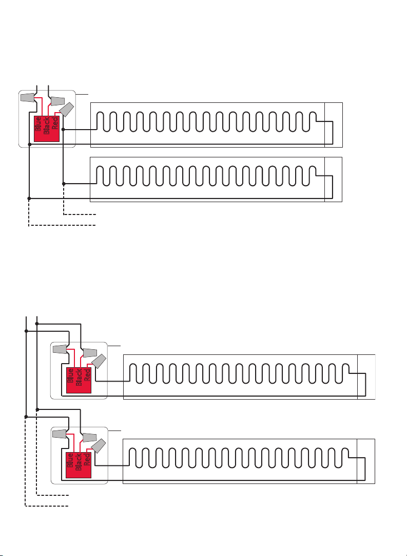
Connecting multiple heaters to the same EIM
N L : For 120V application
L2 L1 : For 240V application
Remote junction box or
heater wiring compartment
Red
Blue
Black
The maximum number of heaters per EIM
is limited to a maximum load of 12.5 A
Connecting multiple EIMs on the same circuit
N L : For 120V application
L2 L1 : For 240V application
Remote junction box or
heater wiring compartment
Red
Blue
Black
Remote junction box or
heater wiring compartment
Red
Blue
Black
The maximum number of EIMs is 8 per thermostat.
69-2472EF—01 6
Page 7
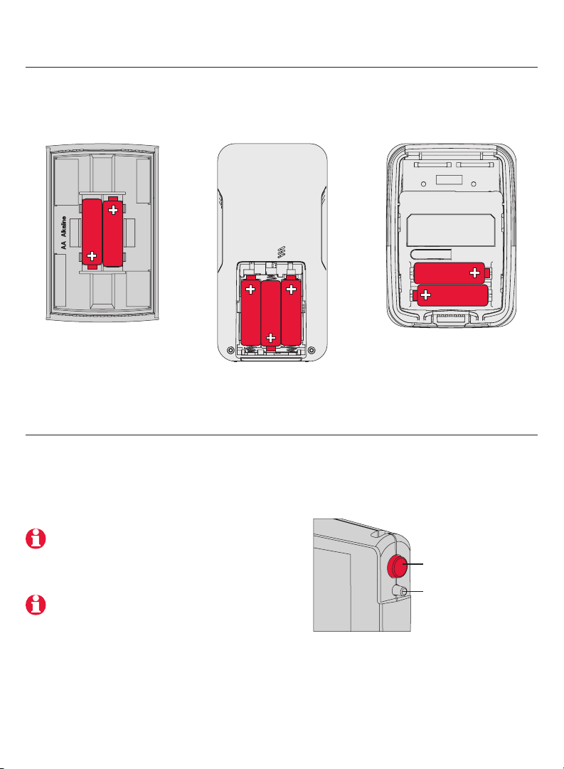
2 Install batteries in wireless devices
EConnect™ TA7210
Thermostat
Install 2 AA alkaline
batteries
Remote control
(optional)
Install 3 AA alkaline
batteries
Outdoor air sensor
(optional)
Install 2 AA lithium
batteries
3 Link all devices to wireless network
Start wireless setup
Press the EIM Connect button to place it in wireless setup. When the amber light
changes to a green flashing light, you can begin to link devices to the wireless network
(see pages 7-10).
If the amber light changes to a red light
instead, there is another EIM currently in
wireless setup. Press the Connect button
on the other EIM to exit its wireless setup.
If the green flashing light disappears (after
a delay of 15 minutes) before you have time
to link all your devices, press the Connect
button again.
* Flashing green: Ready for connection
Steady green: Connection established
Steady red: Connection failure
Connect button
Connect LED *
7 69-2472EF—01
Page 8
Installation Guide
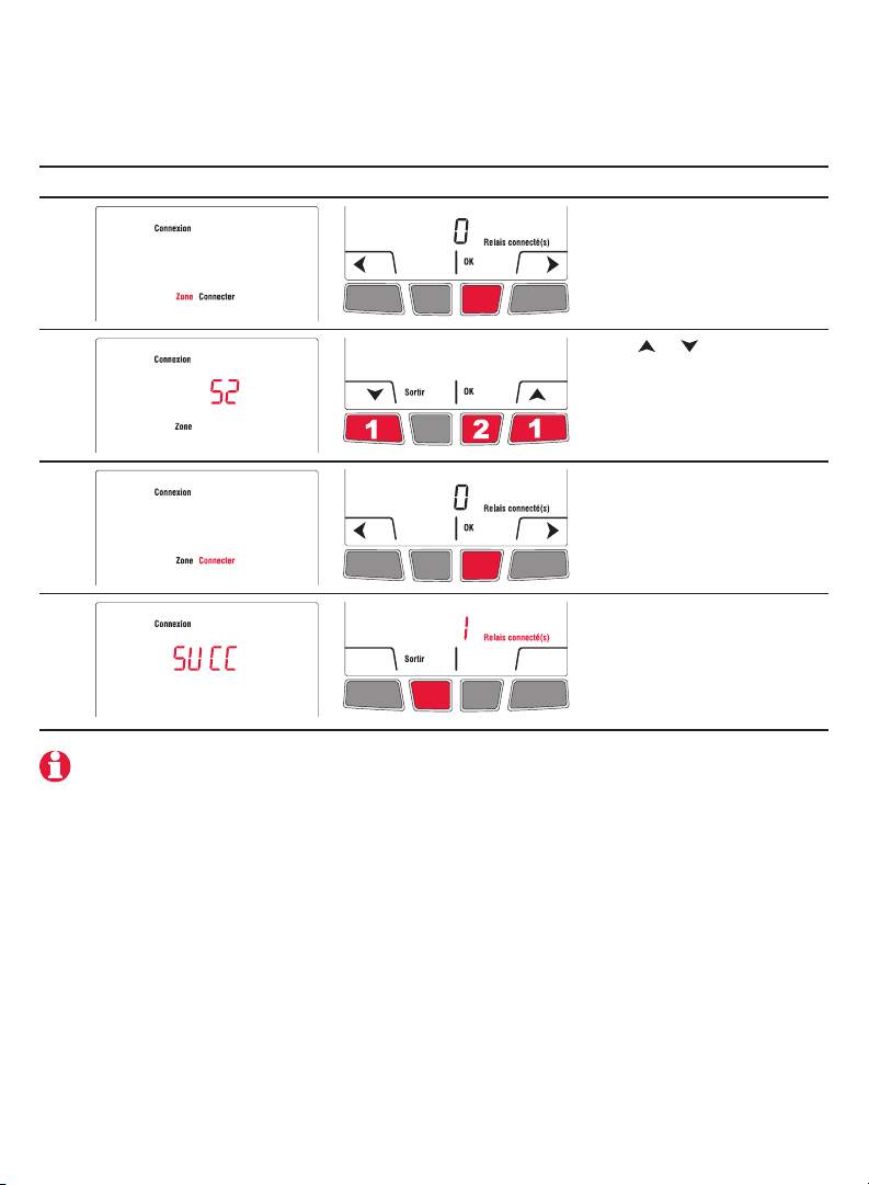
Link thermostat and EIM to wireless network
Perform the following steps on the thermostat:
# Display Button Step
1
The Connexion (link) menu
appears when you connect
the thermostat to wireless
network for the first time.
Press Ok to select Zone.
2
3
4
Press or to change the
zone name (optional; see
page 17) and press OK.
Press OK to select
Connecter (connect).
SUCC (success) confirms
the connection is successful.
Press Sortir (exit) once to
link another EIM (see page 9)
or 3 times to return to home
screen.
If an error code (E followed by a number) appears on the screen, see its explanation
on page 20.
69-2472EF—01 8
Page 9
EConnect™ TA7210
Link additional EIM to wireless network (optional)
Perform steps 1 to 6 for each additional EIM. You can link a maximum of 8 EIMs to
the wireless network:
1 If the green light on the previously-linked EIM is flashing, press its Connect button.
The green light will become steady.
2 Press the Connect button on the next EIM you wish to link and wait for its green
flashing light.
Skip steps 3 and 4 if the thermostat is displaying the Connexion menu
(as shown in step 5).
# Display Button Step
3
Press and hold the right
center button for 5 secs.
4
5
6
9 69-2472EF—01
From the installer’s setup
menu, press to select
Connexion (link) and
press Ok.
Press to select
Connecter autre (connect
more) and press Ok.
SUCC (success) confirms
the connection is successful.
Press Sortir (exit) once and
go back to step 1 to link
another EIM or press Sortir
(exit) 3 times to return to
home screen.
Page 10
Installation Guide
Link outdoor sensor to wireless network (optional)
1 Make sure the Connect light on the EIM is
flashing (see page 7).
If you have more than one wireless thermostat, make
sure to activate the wireless setup from an EIM
linked to the thermostat. For example, to display
the outdoor temperature on thermostat Y, you must
activate the wireless setup from either EIM B or C,
not A.
2 Press the Connect button on the back of the
sensor.
3 After 15 seconds, check if the thermostat is displaying a value for the outdoor
temperature reading.
If you have more than one wireless thermostat, repeat steps 1 and 3 for each thermostat.
Press and
release
Bathroom
wireless network
Thermostat X
EIM A
Outdoor
sensor
Remote
control
Bedroom
wireless network
Thermostat Y
EIM B
EIM C
Link remote control to wireless network (optional)
1 Make sure the Connect light on the EIM is flashing (see page 7).
If you have more than one wireless thermostat, make sure to activate the wireless setup from
an EIM linked to the thermostat. For example, to link the remote control to thermostat Y, you
must activate the wireless setup from either EIM B or C, not A.
2 Press CONNECT at the remote control.
3 When the remote control displays
Connected (after a short delay), press
DONE.
4 Press NO at the next screen to save and exit.
(Or press YES and repeat steps 1-4 to link to
another network).
CONNECT
WIRELESS SETUP
Press to link to
another network
CONNECT MORE?
NOYES
Press to save
and exit
69-2472EF—01 10
Page 11
EConnect™ TA7210
4 Exit wireless setup
1 Press the EIM Connect button. Its green flashing light will change to a steady green
light.
If you do not press the connect button, the EIM will automatically exit wireless setup after 15
minutes of inactivity.
2 Put the cover back on the antenna module.
5 Customize the thermostat
Accessing the installer setup menu
• To access the installer setup menu from the home screen,
press and hold the right center button for 5 secs.
Navigating the menus
• Press or to navigate the menus and setup functions.
• Press OK to select the flashing menu or setup function.
Modifying the settings
• Press or to modify the displayed setting.
• Press OK to save the displayed setting. The setting will
flash to confirm that it has been saved.
Exiting the menus
• Press Sortir (Exit) once to return to the previous menu or
as many times as necessary to return to the home screen.
If you press Sortir (exit) after you have changed a setting, the
new setting will not be saved. Make sure you press Ok to save
the new setting before you press Sortir (exit).
11 69-2472EF—01
Page 12
Installation Guide
Installer setup table
Setup function Options Default setting To modify, see
Temperature unit °C / °F °C Page 12
Time format 12h / 24h 24h Page 12
Minimum setpoint 5°C to 30°C (41°F to 86°F) 5°C (41°F) Page 13
Maximum setpoint 5°C to 30°C (41°F to 86°F) 30°C (86°F) Page 13
Programmable mode On / Off On Page 14
Keypad lock None / Partial / All None Page 15
Zone name 1, ..., 57 52 Pages 16-17
Adaptive Intelligent Recovery On / Off On Page 18
Anti-freeze On / Off On Page 18
To set the date & time, the schedule and the automatic daylight savings, refer to User’s Guide.
Temperature unit / Time format
Follow this procedure to select the temperature unit (°C or °F) and time format
(12h or 24h).
The time format selection is available only if the thermostat is in programmable mode.
# Display Button Step
1
2
3
69-2472EF—01 12
From the installer’s setup
menu, press OK to select the
Format menu.
Press or to change the
temperature unit. Press OK.
Press or to change the
time format. Press OK.
Page 13

EConnect™ TA7210
Minimum and maximum setpoints
Follow this procedure to set the minimum and maximum setpoint temperature.
# Display Button Step
1
From the installer’s setup
menu, press to select
Consignes (setpoints) and
press OK.
2
3
4
5
6
Press OK to select Min.
Press or to change the
minimum setpoint. Press
OK.
Press OK to select Max.
Press or to change the
maximum setpoint. Press
OK.
Press Sortir (exit) once to
return to installer’s setup
menu or twice to return to
home screen.
13 69-2472EF—01
Page 14
Installation Guide
Programmable mode
The thermostat is factory-set as a 7-day programmable thermostat. To set it as a nonprogrammable thermostat, proceed as follows:
# Display Button Step
1
From the installer’s setup
menu, press to select
Horaire (schedule) and
press OK.
2
Press or to select Non
and press OK.
Copy
Use this function to copy the configuration settings, the schedule settings or both to
other EConnect™ wireless thermostats in your house. This function is available only if the
thermostat is connected either to a remote control or outdoor sensor. The settings are
copied to other thermostats connected to the remote control or outdoor sensor.
# Display Button Step
1
2
From the installer’s setup
menu, press as needed to
select Copie and press OK.
Press or to select
Horaire (schedule),
Configuration or both.
Press OK.
3
69-2472EF—01 14
Patientez (wait) may appear
for several minutes. When
SUCC (success) appears,
press Sortir (exit) to return
to home menu.
Page 15
Keypad lock
By default, the keypad lock is disabled.
EConnect™ TA7210
If you leave at Non
(no), the homeowner
will have full access
to all thermostat
functions.
# Display Button Step
1
2
If you select
Part (Partial), the
homeowner can
change the room
temperature only.
If you select Oui (yes),
the buttons will not
appear on the screen.
To unlock, go to Installer
Setup (see page 11).
From the installer’s setup
menu, press to select
Verrouiller (lock) and press
OK.
Press or to select Oui
(Yes), Part (Partial) or Non
(No). Press OK.
15 69-2472EF—01
Page 16
Installation Guide
Zone name
The zone name is used to identify the thermostat on the wireless remote control. By
default, the zone name is Thermostat (zone name 52). If you have a wireless remote
control and more than one wireless thermostat, change the zone name of the thermostat
to identify it from the other thermostats. For example, if the thermostat is in the living
room, set the zone to 31.
# Display Button Step
1
From the installer’s setup
menu, press to select
Connexion (link) and
press OK.
2
3
4
Press OK to select Zone.
Press or to set the zone
name (see page 17). Press
OK.
Press Sortir (exit) once to
return to installer’s setup
menu or twice to return to
home screen.
69-2472EF—01 16
Page 17

EConnect™ TA7210
Zone name list
Zone Name Zone Name Zone Name Zone Name
1 Basement 16 Exercise Room 30 Library 44 Porch
2 Bathroom 17 Family Room 31 Living Room 45 Rec Room
3 Bathroom 1 18 Fireplace 32 Lower Level 46 Sewing Room
4 Bathroom 2 19 Foyer 33 Master Bath 47 Spa
5 Bathroom 3 20 Game Room 34 Master Bed 48 Storage Room
6 Bedroom 21 Garage 35 Media Room 49 Studio
7 Bedroom 1 22 Great Room 36 Music Room 50 Sun Room
8 Bedroom 2 23 Guest Room 37 Nursery 51 Theater
9 Bedroom 3 24 Gym 38 Office 52 Thermostat
10 Bedroom 4 25 Kid’s Room 39 Office 1 53 Upper Level
11 Boat House 26 Kitchen 40 Office 2 54 Utility Room
12 Bonus Room 27 Kitchen 1 41 Pantry 55 Walk In Closet
13 Computer Room 28 Kitchen 2 42 Play Room 56 Wine Cellar
14 Den 29 Laundry Room 43 Pool Room 57 Workshop
15 Dining Room
Adaptive Intelligent Recovery (horaire anticipé)
Available only if you use the thermostat in programmable mode.
When Adaptive Intelligent Recovery is on, the thermostat “learns” how long your heater
takes to reach the set temperature. The thermostat will then determine when to activate
heating so the desired temperature is attained at the desired time. The thermostat
reassesses the heating start time daily based on the previous day’s performance. When
Adaptive Intelligent Recovery is off, heating starts at the set time.
To turn off Adaptive Intelligent Recovery, proceed as follows:
# Display Button Step
1
2
17 69-2472EF—01
From the installer’s setup
menu, press to select
Horaire Anticipé
(Adaptive Intelligent
Recovery) and press Ok.
Press or to select Non
(no) and press OK.
Page 18

Installation Guide
Anti-freeze
When this function is on, the EIM will maintain the room temperature at 13°C (55°F) if it
loses communication with the thermostat or if the thermostat sensor is defective.
Leave the protection on unless the EIM is installed in a junction box in a separate room
from the heater.
To turn off the Anti-freeze protection, proceed as follows:
# Display Button Step
1
From the installer’s setup
menu, press as needed to
select Hors-Gel (anti-freeze)
and press OK.
2
Press or to set to Non
(no). Press OK.
System test
1 From the Home screen, press until the setpoint temperature is above the room
ambient temperature by at least 2°. Press Temporaire (temporary).
2 Wait for Chauffe (heat) to display on the thermostat.
3 Verify if the heater becomes hot.
4 Press Annuler (cancel) to return the thermostat to its previous mode.
69-2472EF—01 18
Page 19

EConnect™ TA7210
6 Mount thermostat and outdoor sensor
Follow the guidelines below when mounting the thermostat:
• Do NOT install the thermostat in an area where it can be exposed to water or rain.
• Avoid locations where there are air drafts (top of staircase, air outlet), dead air spots
(behind a door), direct sunlight or concealed chimney or stove pipes.
• For a new installation, choose a location about 1.5 m (5 ft.) above the floor.
• Install the thermostat on an inside wall facing the heater.
• Keep the thermostat’s top and bottom air vents (openings) clean and unobstructed at
all times.
Two mounting plates are provided for mounting the thermostat on the wall or on a
junction box. Use Method A for a slimmer thermostat look. Choose Method B if you
prefer not to make an opening in the wall. Method C must be used for installation on a
junction box.
Recessed mounting on a wall (Method A)
Mark the four corners and join
them to create a rectangular
outline.
Mounting on a
wall (Method B)
Secure the mounting
plate to the wall using
provided wall anchors
and screws.
19 69-2472EF—01
Cut along the outline to create
an opening in the wall.
Mounting on a junction box
(Method C)
Use mounting plate with no opening.
Secure the mounting plate to a junction
box using provided mechanical
screws.
Secure the mounting plate to
the wall using provided wall
anchors and screws.
Installing
faceplate
Complete the thermostat
installation by pressing
the faceplate against the
mounting plate.
Page 20

Installation Guide
Mounting the outdoor sensor (optional)
Mount the sensor vertically on
an exterior wall, at least 6 inches
below any overhang. Choose a
location protected from direct
sunlight.
Place sensor securely in bracket,
facing away from wall.
Error codes
Display Description
LO
The indoor temperature is below 0°C (32°F).
HI
The indoor temperature is above 60°C (140°F).
- -
The temperature reading is currently unavailable or the sensor is defective.
E128
E129
E130
E134
E137
E138
E152
The wireless network setup must be redone.
Attempting to connect incompatible wireless devices.
Invalid address. Call customer assistance.
Low signal strength. Move wireless device to a different location and try again.
Maximum number of devices is exceeded.
Make sure Connected light on EIM is flashing and you are 2+ feet away from EIM.
Incorrect order. Make sure to link EIM to proper thermostat.
69-2472EF—01 20
Page 21

EConnect™ TA7210
Verifying the signal strength between the EIM and the
thermostat
If you have more than one EIM linked to the thermostat, the displayed value is between
the thermostat and the first-linked EIM. The signal strength ranges from 0 (no signal) to
10 (strongest).
# Display Button Step
1
From the home screen, press
and hold the right center
button for 5 secs.
2
3
4
Press to select
Connexion (link) and
press OK.
Press to select Signal
and press OK.
The signal strength is
displayed. Press Sortir (exit)
twice to return to installer’s
setup menu or three times to
return to home screen.
Replacing wireless devices
Thermostat
To replace the thermostat, install batteries in the new thermostat (see page 7) and link it
to the wireless network (see page 8). To customize the thermostat, see pages 11-18.
If more than one EIM were linked to the old thermostat, you can link the new thermostat from
any one of these EIMs.
21 69-2472EF—01
Page 22

Installation Guide
Remote control or outdoor sensor
To replace the remote control or the outdoor sensor, install batteries in the new device
(see page 7) and link it to the wireless network (see page 10).
If more than one EIM are linked to the same thermostat, you can link the remote control or the
outdoor sensor from any one of these EIMs.
If you have more than one wireless thermostat, link the remote control or the outdoor sensor
from one EIM of each of the wireless thermostats.
Equipment interface module (EIM)
If you have a remote control:
1 Press and hold, for about 3 seconds, the blank space (or
arrow if present) in the lower right corner of the screen until
the display changes.
2 Press REMOVE, then YES.
If you have only one EIM linked to the thermostat:
Remove the defective EIM, install a new one (see pages 3-6) and proceed as follows:
1 Check if the thermostat displays 0 Relais connecté(s) (0 relay
connected) as shown on the right. If so, go straight to step 5.
2 From the home screen, press and hold the right center button for 5
secs.
3 Press to select Connexion (link) and press Ok.
4 Press to select Enlever (remove) and press Ok. The thermostat will
display 0 Relais connecté(s) (0 relay connected).
5 Follow the procedures on pages 7-11 to set up a new network with the new EIM.
If you have more than one EIM linked to the thermostat:
Follow the procedure below to identify the defective EIM(s) and to reestablish all links:
1 Remove the antenna cover from each EIM in the network by squeezing
the cover (as shown by red arrows) and pulling it out.
2 Press, for 10 seconds, the Connect button on every EIM that has a
green light. Repeat this step until none of the EIM shows a green light.
3 Check if the thermostat displays 0 Relais connecté(s) (0 relay connected) as
shown on the right. If so, go straight to step 7.
4 From the home screen, press and hold the right center button for 5 secs.
5 Press to select Connexion (link) and press Ok.
6 Press to select Enlever (remove) and press Ok. The thermostat will
display 0 Relais connecté(s) (0 relay connected).
7 Follow the procedures on pages 7-11 to create a new network. You
will know that an EIM is defective if its light turns red or the thermostat
displays an error code when you try to link the EIM to the network.
Replace it before continuing to link other EIMs.
Press here
69-2472EF—01 22
Page 23

EConnect™ TA7210
Specifications & replacement parts
Thermostat
Temperature setpoint range: 5°C - 30°C (41°F - 86°F)
Temperature setpoint resolution: 0.5°C (1°F)
Temperature display range: 0°C - 40°C (32°F - 104°F)
Temperature display resolution: 0.5°C (1°F)
Heating cycle rate: 15 minutes
Programming: 5-2 days, 7 days, 1 day or Non-Programmable
Operating Ambient Temperature
Thermostat: 0°C - 50°C (32°F - 122°F)
Remote control: 0°C - 48.9°C (32°F - 120°F)
EIM (relay): -20°C - 60°C (-4°F - 140°F)
EIM (antenna): -20°C - 60°C (-4°F - 140°F)
Outdoor air sensor: -40°C - 60°C (-40°F - 140°F)
Operating Relative Humidity
Thermostat: 5% - 90% (non-condensing)
Remote control: 5% - 90% (non-condensing)
EIM (relay): 5% - 95% (non-condensing)
EIM (antenna): 5% - 95% (non-condensing)
Outdoor air sensor: 0% - 100% (condensing)
Physical Dimensions (height, width, depth)
Thermostat: 130 x 82 x 29 mm (5.13 x 3.22 x 1.14 inches)
EIM (relay): 73 x 63 x 29 mm (3.03 x 2.49 x 1.28 inches)
EIM (antenna): 71 x 62 x 33 mm (2.89 x 2.63 x 1.16 inches)
Outdoor air sensor: 127 x 89 x 43 mm (5.00 x 3.50 x 1.68 inches)
Electrical Ratings (EIM)
Supply: 100-240 VAC, 50/60 Hz
Minimum load: 0.4 A (resistive only)
Maximum load: 12.5 A (resistive only)
Accessories & Replacement Parts
Item Part Number
Equipment Interface Module (EIM) ATM100-SPK
Remote control REM5000R1001
Outdoor air sensor C7089R1013
Antenna cover (white) 50055751-002
Antenna cover (almond) 50055751-004
23 69-2472EF—01
Page 24

Installation Guide
Regulatory information
FCC Compliance Statement (Part 15.19) (USA only)
This device complies with Part 15 of the FCC Rules. Operation is subject to the following two
conditions:
1) This device may not cause harmful interference, and
2) This device must accept any interference received, including interference that may cause
undesired operation.
FCC Warning (Part 15.21) (USA only)
Changes or modifications not expressly approved by the party responsible for compliance could
void the user’s authority to operate the equipment.
FCC Interference Statement (Part 15.105 (b)) (USA only)
This equipment has been tested and found to comply with the limits for a Class B digital device,
pursuant to Part 15 of the FCC Rules. These limits are designed to provide reasonable protection
against harmful interference in a residential installation. This equipment generates uses and can
radiate radio frequency energy and, if not installed and used in accordance with the instructions,
may cause harmful interference to radio communications. However, there is no guarantee that
interference will not occur in a particular installation. If this equipment does cause harmful
interference to radio or television reception, which can be determined by turning the equipment off
and on, the user is encouraged to try to correct the interference by one of the following measures:
• Reorient or relocate the receiving antenna.
• Increase the separation between the equipment and receiver.
• Connect the equipment into an outlet on a circuit different from that to which the receiver is
connected.
• Consult the dealer or an experienced radio/TV technician for help.
EIM, thermostats and outdoor sensor
To comply with FCC and Industry Canada RF exposure limits for general population/ uncontrolled
exposure, the antenna(s) used for these transmitters must be installed to provide a separation
distance of at least 20 cm from all persons and must not be co-located or operating in conjunction
with any other antenna or transmitter.
Remote Control
This portable transmitter with its antenna complies with FCC and Industry Canada RF exposure
limits for general population/uncontrolled exposure. This device must not be co-located or
operating in conjunction with any other antenna or transmitter.
Section 7.1.3 of RSS-GEN
Operation is subject to the following two conditions:
1) This device may not cause interference, and
2) This device must accept any interference, including interference that may cause undesired
operation of the device.
Section 7.1.2 of RSS-GEN
Under Industry Canada regulations, this radio transmitter may only operate using an antenna of
type and maximum (or lesser) gain approved for the transmitter by Industry Canada. To reduce
potential radio interference to other users, the antenna type and its gain should be so chosen that
the equivalent isotropically radiated power (EIRP) is not more than that necessary for successful
communication.
69-2472EF—01 24
Page 25

Page 26

Need Help?
For assistance with this product please visit www.aubetech.com,
or call Honeywell Customer Care toll-free at 1-800-831-2823.
Solutions de régulation et d’automatisation
Honeywell International Inc.
1985 Douglas Drive North
Golden Valley, MN 55422
http://customer.honeywell.com
69-2472EF-01
06-2011
© 2011 Honeywell International Inc.
® U.S. Registered Trademark.
All rights reserved.
Printed in USA
Honeywell Limited
705 Montrichard
Saint-Jean-sur-Richelieu, Québec, J2X 5K8
www.aubetech.com
Page 27

Guide
d’installation
du système
EConnectMC Ensemble de thermostat sans fil TA7210
Avec module d’interface
Guide d’installation pour :
• Module d’interface sans fil
• Thermostat sans fil EConnect
• Télécommande sans fil
• Sonde extérieure sans fil
DIRECTIVES IMPORTANTES
DANGER ÉLECTRIQUE
Peut provoquer des chocs électriques ou des dommages matériels. Mettre
hors tension avant de commencer l’installation.
Doit être installé par un électricien certifié. Lire attentivement les
directives. La non-conformité aux directives risque d’endommager le produit ou
de constituer un danger.
MC
Besoin d’aide?
Pour obtenir de l’aide sur ce produit, veuillez consulter le www.aubetech.com
ou joindre sans frais le service à la clientèle d’Honeywell au 1 800 831-2823.
69-2472EF-01
Page 28

Guide d’installation
Installation du système en un coup d’oeil
Le module d’interface avec le matériel (MIM) permet de commander une plinthe
électrique, un convecteur ou un ventiloconvecteur de 120 volts, 208 volts ou de 240 volts
à partir d’un thermostat sans fil EConnectMC.
Thermostat
MIM dans l’appareil
de chauffage
Télécommande
Sonde
extérieure
MIM dans une
boîte de jonction
Panneau
électrique
Thermostat
Appareil de chauffage
Alimentation Connection sans fil
Étapes d’installation
1 Installation du module d’interface avec le matériel (MIM) ...................Pages 3 - 6
2 Insertion des piles dans les dispositifs sans fil ........................................... Page 7
3 Connexion des dispositifs au réseau sans fil .....................................Pages 7 - 10
4 Sortir de la configuration de réseau sans fil ............................................. Page 11
5 Personnalisation du thermostat (menu de l’installateur) ..................Pages 11 - 18
6 Installation du thermostat et de la sonde extérieure ........................Pages 19 - 20
Pour les codes d’erreur, voir la page 20.
Pour vérifier la force du signal, voir la page 21.
Pour remplacer un dispositif sans fil, voir les pages 21-22.
Pour la fiche technique et la liste des pièces de remplacement, voir la page 23.
CONSERVER CES DIRECTIVES
69-2472EF—01 2
Page 29

EConnectMC TA7210
1 Installation du module d’interface avec le matériel (MIM)
Déterminer l’emplacement
Le module d’interface avec le matériel (MIM) consiste d’un relais et d’une antenne. Ils
peuvent être installés soit dans le compartiment de câblage de la plinthe électrique ou
dans une boîte de jonction carrée de 4-11/16 pouces.
La distance minimale entre les MIMs est de 2 pieds (0.6 m). Cette consigne doit être respectée
même si les MIMs sont séparés par un mur.
• Installation dans une plinthe électrique
Vous pouvez installer le MIM dans le
compartiment de câblage de la plinthe
électrique si celle-ci figure dans la liste
suivante:
Marque Séries
Cadet F
Global Commander CCB
King Electrical K, CB, KP, M
Marley 2500, BKOC, QMKC
Ouellet ODBA, ODI, ODIA, OFM, OPR
Stelpro CBB, N, SCA, SCAS
TPI 2900C, 2900S, 3700, 3900
Le produit est compatible avec les plinthe électriques énumérées dans la liste cidessus. Si
votre plinthe ne figure pas dans cette liste, installer le MIM dans une boîte de jonction ou
remplacer votre plinthe avec une de la liste.
• Installation dans une boîte de jonction
Installer le MIM dans une boîte de jonction :
• si vous avez un convecteur ou ventiloconvecteur.
• si vous ne pouvez ou ne désirez pas installer le
MIM dans votre plinthe.
La boîte de jonction peut être installée n’importe où dans la
maison; exemple près du panneau électrique.
Relais
Antenne
AntenneRelais
3 69-2472EF—01
Page 30

Guide d’installation
Installation dans une plinthe électrique
DANGER ÉLECTRIQUE
Peut provoquer des chocs électriques ou causer des dommages aux équipements.
Mettre hors tension avant de commencer l’installation.
Le câblage doit être conforme aux codes électriques locaux. Si les fils d’alimentation sont
en aluminium, utilisez des connecteurs CO/ALR conçu à cet effet.
Débrancher les fils de la plinthe des fils d’alimentation. Enlever le thermostat si celui-ci est
intégré dans la plinthe.
1 Enlever l’entrée défonçable sur le côté de la
plinthe.
Positionner le relais de sorte
que les fils sont en haut
3 Nettoyer le panneau arrière à l’intérieur du
compartiment de câblage où le relais sera installé.
Décoller la bande adhésive du relais et installer le
relais sur le panneau arrière.
5 Insérer la fiche de l’antenne dans la prise du relais
jusqu’à ce que vous entendiez un clic.
69-2472EF—01 4
2 Retirer l’écrou de l’antenne et décoller la bande
adhésive. Passer le fil de l’antenne à travers
l’ouverture et installer l’antenne à la verticale tel
qu’illustré. Remettre l’écrou et le serrer.
N L : Installation 120V
L2 L1 : Installation 240V
Bleu
Noir
Rouge
4 Relier les fils de la plinthe et les fils d’alimentation
à ceux du relais.
Voir la page 6 si vous reliez plus d’une plinthe.
installer un
capuchon
s’il y a lieu.
6 Remettre le couvercle de la plinthe. (Si un
thermostat était intégré dans la plinthe, installer un
capuchon pour boucher le trou.) Mettre la plinthe
sous tension. Ne pas mettre le couvercle du
module d’antenne.
DANGER ÉLECTRIQUE
Peut provoquer des chocs électriques. Remettre le
couvercle avant de mettre la plinthe sous tension.
Page 31

Installation dans une boite de jonction
DANGER ÉLECTRIQUE
Peut provoquer des chocs électriques ou causer des dommages aux équipements.
Mettre hors tension avant de commencer l’installation.
Le câblage doit être conforme aux codes électriques locaux. Si les fils d’alimentation sont
en aluminium, utilisez des connecteurs CO/ALR conçu à cet effet.
EConnectMC TA7210
1 Fixer la boîte de jonction au mur. Enlever une
entrée défonçable, installer une bride de réduction
de tension et passer les fils de l’appareil de
chauffage et de l’alimentation. Enlever une autre
entrée défonçable pour l’installation de l’antenne
(étape 2).
Positionner le relais de sorte
que les fils soient en haut
3 Nettoyer l’intérieur la boîte de jonction où le relais
sera installé. Décoller la bande adhésive du relais
et installer le relais dans la boîte.
5 Insérer la fiche de l’antenne dans la prise du relais
jusqu’à ce que vous entendiez un clic.
2 Retirer l’écrou de l’antenne et décoller la bande
adhésive. Passer le fil de l’antenne par l’ouverture
de l’entrée défonçable et installer l’antenne.
Remettre l’écrou et le serrer.
N L : Installation 120V
L2 L1 : Installation 240V
Noir
Rouge
Vers l’appareil
de chauffage
Bleu
4 Connecter les fils de l’appareil de chauffage et les
fils d’alimentation à ceux du relais.
Voir la page 6 si vous reliez plus d’un appareil
de chauffage.
6 Installer un couvercle sur la boîte de
jonction et mettre l’appareil de chauffage sous
tension. Ne pas mettre le couvercle du module
d’antenne.
DANGER ÉLECTRIQUE
Peut provoquer des chocs électriques. Mettre
le couvercle sur la boîte de jonction avant de
mettre l’appareil de chauffage sous tension.
5 69-2472EF—01
Page 32

Guide d’installation
Connexions de plusieurs appareils de chauffage au même MIM
N L : Installation 120V
L2 L1 : Installation 240V
Boîte de jonction ou
compartiment de cablage
Bleu
Noir
Rouge
Le nombre maximale d’appareil de chauffage par
MIM est sujette à une charge maximale de 12,5 A
Connexions de plusieurs MIMs sur le même circuit
N L : Installation 120V
L2 L1 : Installation 240V
Boîte de jonction ou
compartiment de cablage
Bleu
Noir
Rouge
Boîte de jonction ou
compartiment de cablage
Bleu
Noir
Rouge
Le nombre maximale de MIMs est de 8 par thermostat
69-2472EF—01 6
Page 33

2 Installation des piles
EConnectMC TA7210
Thermostat
Insérer 2 piles alcaline AA
Télécommande
(facultatif)
Insérer 3 piles alcaline AA
Sonde extérieure
(facultatif)
Insérer 2 piles lithium AA
3 Connexion des dispositifs au réseau sans fil
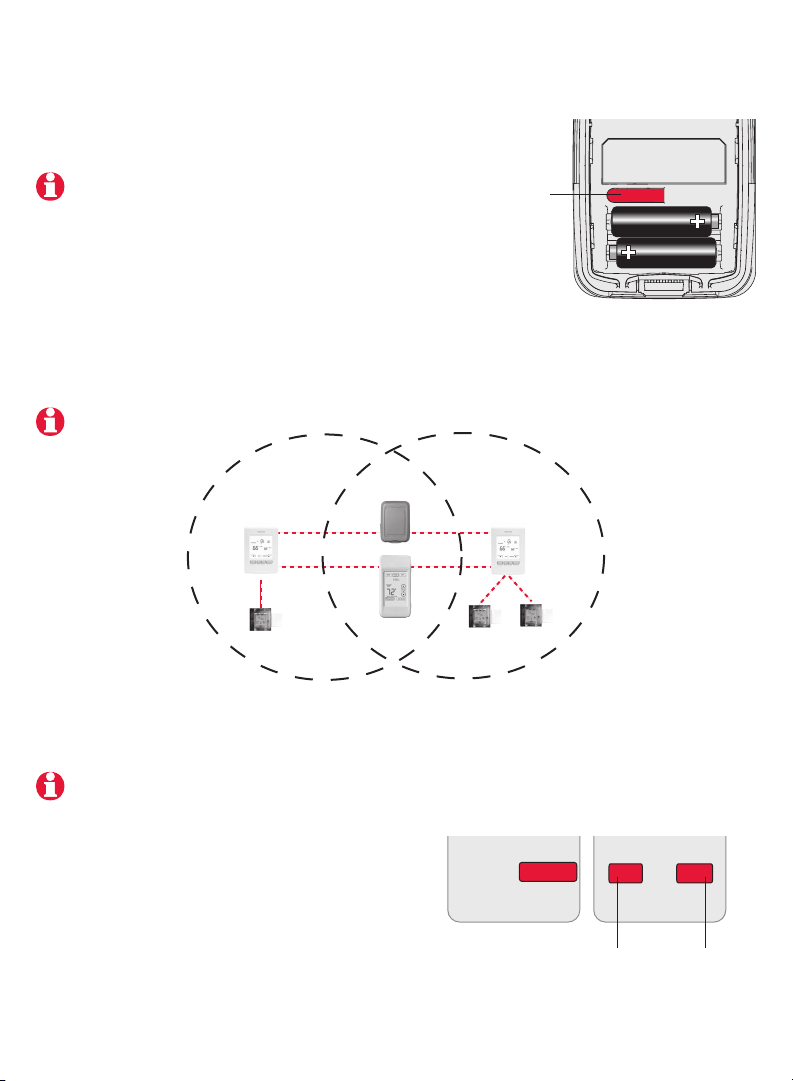
Activer la configuration du réseau sans fil
Appuyer sur le bouton de connexion du MIM pour activer la configuration du réseau
sans fil. Lorsque le voyant ambre devient un clignotant vert, vous êtes prêt à relier les
dispositifs au réseau sans fil (voir les pages 7-10).
Si le voyant ambre devient rouge, il y a
un autre MIM en cours de configuration
du réseau. Appuyer sur le bouton de
connexion de l’autre MIM pour le sortir de
la configuration du réseau.
Si le clignotant vert disparaît (après un délai
de 15 minutes) avant que vous n’ayez eu le
temps de relier tous les dispositifs, appuyez
de nouveau sur le bouton de connexion.
* Clignotant vert : Prêt pour la connexion
Voyant vert : Connexion établie
Voyant rouge : Connexion échouée
Bouton de
connexion
Voyant de
connexion *
7 69-2472EF—01
Page 34

Guide d’installation
Relier le thermostat et le MIM au réseau sans l
Exécuter les étapes suivantes sur le thermostat :
# Affichage Boutons Étapes
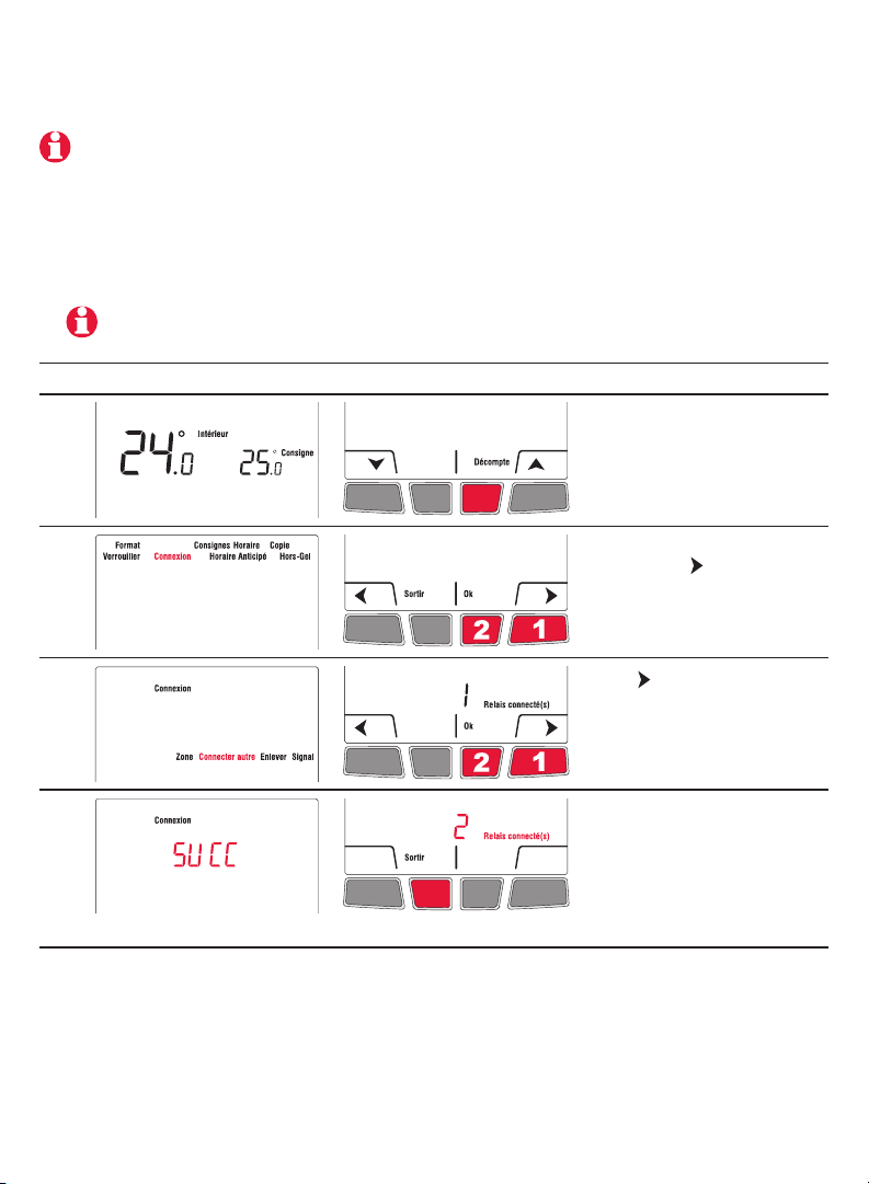
1
2
Le menu Connexion
apparaît lorsque vous reliez
le thermostat au réseau
sans fil pour la première
fois. Appuyez sur Ok pour
sélectionner Zone.
Appuyer sur ou pour
changer le nom de la zone
(facultatif; voir la page 17) et
appuyer sur Ok.
3
4
Si le thermostat affiche un code d’erreur (E suivi d’un numéro), voir l’explication à la page 20.
Appuyer sur Ok pour
sélectionner Connecter.
SUCC (succès) confirme
que la connexion est réussie.
Appuyer sur Sortir une fois
pour relier un autre MIM (voir
page 9) ou 3 fois pour revenir
à l’écran d’accueil.
69-2472EF—01 8
Page 35

EConnectMC TA7210
Relier des MIM additionnels au réseau sans l (facultatif)
Exécuter les étapes 1 à 6 pour chaque MIM additionnel. Vous pouvez relier un maximum de 8
MIMs au réseau sans fil.
1 Si le voyant vert sur le dernier MIM que vous avez relié clignote encore, appuyer sur
son bouton de connexion. Le voyant vert cessera de clignoter.
2 Appuyer sur le bouton de connexion du MIM que vous désirez relier et attendre que
le voyant vert clignote.
Sauter les étapes 3 et 4 si le menu Connexion est encore affiché à l’écran (voir l’étape 5).
# Affichage Boutons Étapes
3
Appuyer et maintenir le
bouton du centre droit
pendant 5 secondes.
4
5
6
9 69-2472EF—01
A partir du menu de
l’installateur, appuyer
sur pour sélectionner
Connexion et appuyer sur
Ok.
Appuyer sur pour
sélectionner Connecter
autre et appuyer sur Ok.
SUCC (Succès) confirme
que la connexion est réussie.
Appuyer sur Sortir une
fois et retourner à l’étape 1
pour relier un autre MIM ou
3 fois pour revenir à l’écran
d’accueil.
Page 36

Guide d’installation
Relier la sonde extérieure au réseau sans l (facultatif)
1 S’assurer que le voyant de connexion du MIM
clignote (voir la page 7).
Si vous avez plus d’un thermostat sans fil, s’assurer
d’activer la configuration à partir du bon MIM. Par
exemple, pour afficher la température extérieure sur
le thermostat Y, vous pouvez activer la configuration
à partir du MIM B ou C, et non A.
2 Appuyez sur le bouton de connexion à l’arrière
de la sonde.
3 Après 15 secondes, vérifier si le thermostat affiche une valeur pour la lecture de la
température extérieure.
Si vous avez plus d’un thermostat sans fil, répétez les étapes 1 et 3 pour chaque thermostat.
Appuyer et
relâcher
Chambre
à coucher
Thermostat Y
MIM B
MIM C
Thermostat X
MIM A
Salle de bain
Capteur
extérieur
Télécommande
Relier la télécommande au réseau sans l (facultatif)
1 S’assurer que le voyant de connexion du MIM clignote (voir la page 7).
Si vous avez plus d’un thermostat sans fil, s’assurer d’activer la configuration à partir d’un
MIM relié au même réseau que le thermostat. Par exemple, pour relier la télécommande au
thermostat Y, vous pouvez activer la configuration à partir du MIM B ou C, et non A.
2 Appuyer sur CONNECT (connecter) de la
télécommande.
3 Lorsque la télécommande affiche Connected
(après un court délai), appuyer sur DONE
(terminé).
4 Appuyer sur NO (non) à l’écran suivant pour
enregistrer et sortir. (Ou appuyer sur YES (oui)
et répéter étapes 1-4 pour relier à un autre
thermostat).
69-2472EF—01 10
CONNECT
WIRELESS SETUP
Appuyer pour
relier à un autre
thermostat
CONNECT MORE?
NOYES
Appuyer pour
enregistrer et
sortir
Page 37

EConnectMC TA7210
4 Sortir de la configuration du réseau sans fil
1 Appuyer sur le bouton de connexion du MIM. Le voyant vert clignotant se
transformera en voyant vert fixe.
Si vous n’appuyez pas sur le bouton de connexion, le MIM sortira automatiquement de la
configuration du réseau sans fil après 15 minutes d’inactivité.
2 Remettre le couvercle sur le module d’antenne.
5 Personnaliser le thermostat
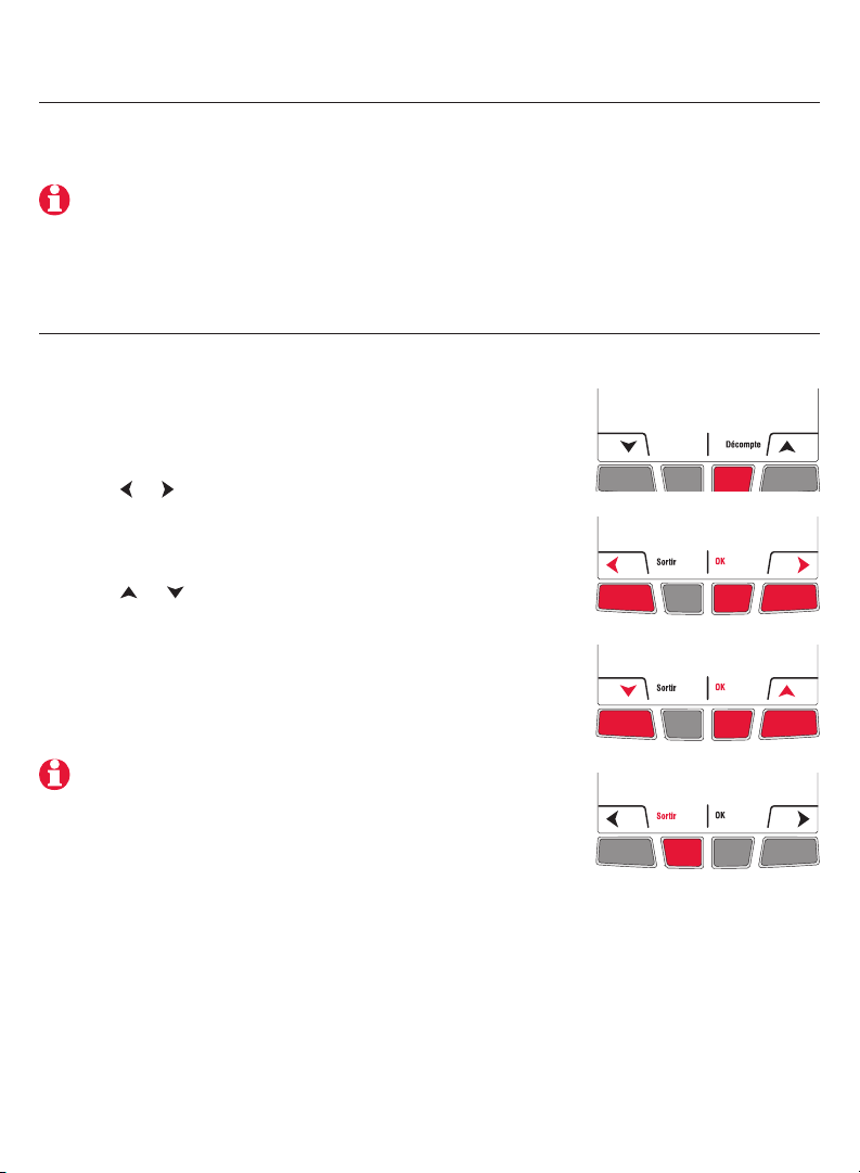
Accéder au menu de l’installateur
• Pour accéder au menu de l’installateur à partir de l’écran
d’accueil, appuyer sur le bouton du centre droit et le
maintenir appuyé pendant 5 secondes.
Naviguer dans les menus
• Appuyer sur ou pour naviguer dans les menus et les
paramètres.
• Appuyer sur Ok pour sélectionner le menu ou le
paramètre lorsque celui-ci clignote.
Modifier les réglages
• Appuyer sur ou pour modifier le réglage affiché.
• Appuyer sur Ok pour enregistrer le réglage affiché. Ce
dernier clignotera pour confirmer qu’il a été enregistré.
Sortir des menus
• Appuyez une fois sur Sortir pour revenir au menu
précédent ou autant de fois que nécessaire pour
revenir à l’écran d’accueil.
Si vous appuyez sur Sortir après avoir modifier un réglage, le nouveau réglage ne sera
pas enregistré. S’assurer d’appuyer sur Ok pour enregistrer le nouveau réglage avant
d’appuyer sur Sortir.
11 69-2472EF—01
Page 38

Guide d’installation
Réglages par défaut
Fonctions Options Réglage par défaut Pour modifier, voir
Unité de température °C / °F °C Page 12
Format de l’heure 12h / 24h 24h Page 12
Consigne minimale 5°C à 30°C (41°F à 86°F) 5 °C (41 °F) Page 13
Consigne maximale 5°C à 30°C (41°F à 86°F) 30 °C (86 °F) Page 13
Mode programmable Activé / Désactivé Activé Page 14
Verrouillage du clavier Désactivé / Partiel /
Complet
Zone 1, ..., 57 52 Pages 16 - 17
Horaire anticipé Activé / Désactivé Activé Page 18
Hors-gel Activé / Désactivé Activé Page 18
Pour régler le jour & l’heure, l’horaire et l’heure d’été automatique, se référer au mode
d’emploi.
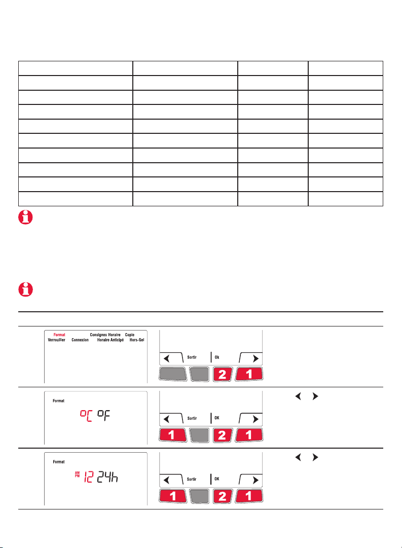
Unité de température / Format de l’heure
Pour sélectionner l’unité de température (° C ou ° F) et le format de l’heure (12h ou 24h).
La sélection du format de l’heure n’est disponible que si le thermostat est en mode
programmable.
Désactivé Page 15
# Affichage Boutons Étapes
1)
2)
3)
69-2472EF—01 12
A partir du menu de
l’installateur, appuyer sur Ok
pour sélectionner le menu
Format.
Appuyer sur ou
pour changer l’unité de
température. Appuyer sur
OK.
Appuyer sur ou pour
changer le format de l’heure.
Appuyer sur OK.
Page 39

Consignes minimale et maximale
Pour régler les températures de consigne minimale et maximale.
# Affichage Boutons Étapes
1
A partir du menu de
l’installateur, appuyer
sur
Consignes et appuyer sur
Ok.
EConnectMC TA7210
pour sélectionner
2
3
4
5
6
Appuyer sur Ok pour
sélectionner Min.
Appuyer sur ou
pour modifier la consigne
minimale. Appuyer sur Ok.
Appuyer sur Ok pour
sélectionner Max.
Appuyer sur ou
pour modifier la consigne
maximale. Appuyer sur Ok.
Appuyer sur Sortir une fois
pour revenir au menu de
l’installateur ou 2 fois pour
revenir à l’écran d’accueil.
13 69-2472EF—01
Page 40

Guide d’installation
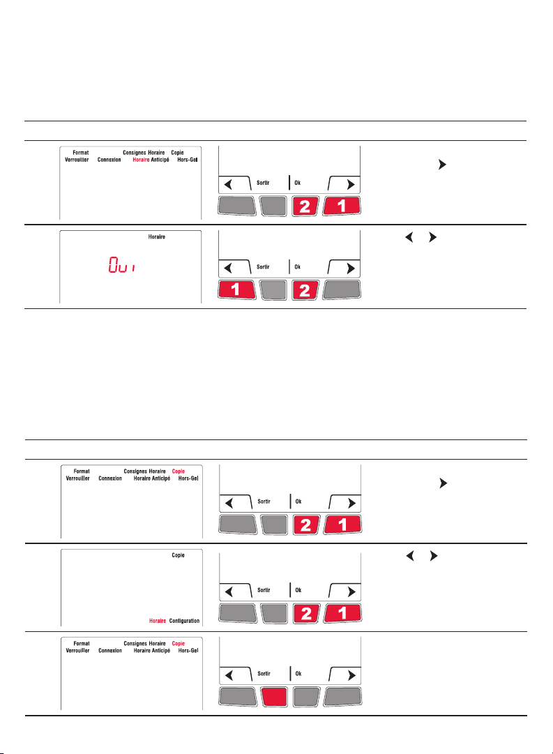
Mode programmable
Le thermostat est réglé en usine comme un thermostat programmable sur 7 jours. Pour le
définir comme un thermostat non programmable, procédez comme suit:
# Affichage Boutons Étapes
1
A partir du menu de
l’installateur, appuyer sur
pour sélectionner Horaire et
appuyer sur Ok.
2
Appuyer sur ou pour
mettre à Non et appuyer
sur Ok.
Copie
Utiliser cette fonction pour copier les réglages de configuration, les réglages de
l’horaire ou les deux aux autres thermostats sans fil EConnectMC de votre résidence.
Cette fonction n’est disponible que si le thermostat est relié à une télécommande ou
à une sonde extérieure. Les paramètres sont copiés aux autres thermostats reliés à la
télécommande ou à la sonde extérieure.
# Affichage Boutons Étapes
1)
2)
A partir du menu de
l’installateur, appuyer sur
pour sélectionner Copie et
appuyer sur Ok.
Appuyer sur ou pour
sélectionner Horaire,
Configuration ou les deux.
Appuyer sur Ok.
3)
69-2472EF—01 14
Patientez pourrait
apparaître pendant quelques
minutes. Lorsque SUCC
(Succès) apparaît, appuyer
sur Sortir pour revenir à
l’écran d’accueil.
Page 41

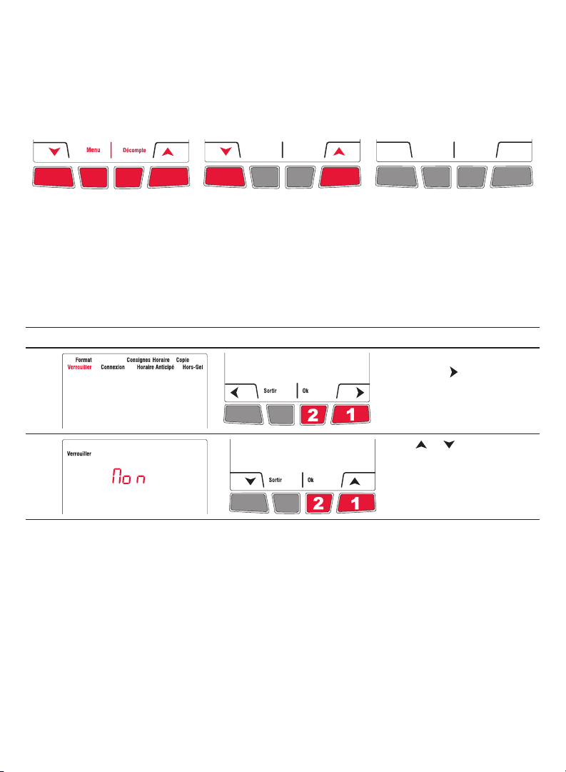
Verrouillage du clavier
Par défaut, le verrouillage est désactivé.
EConnectMC TA7210
Laisser à None pour
avoir plein accès à
tous les réglages du
thermostat.
Sélectionner Part
pour n’avoir accès
qu’au réglage de
la température
ambiante.
Si vous sélectionner
All, les boutons
n’apparaîtront pas
à l’écran. Pour
déverrouiller, voir le menu
de l’installateur (page 37).
# Affichage Boutons Étapes
1
2
A partir du menu de
l’installateur, appuyer sur
pour sélectionner Lock
(verrouiller) et appuyer sur
OK.
Appuyer sur ou pour
mettre à All (complet), Part
(partiel) ou None (désactivé).
Appuyer sur OK.
15 69-2472EF—01
Page 42

Guide d’installation
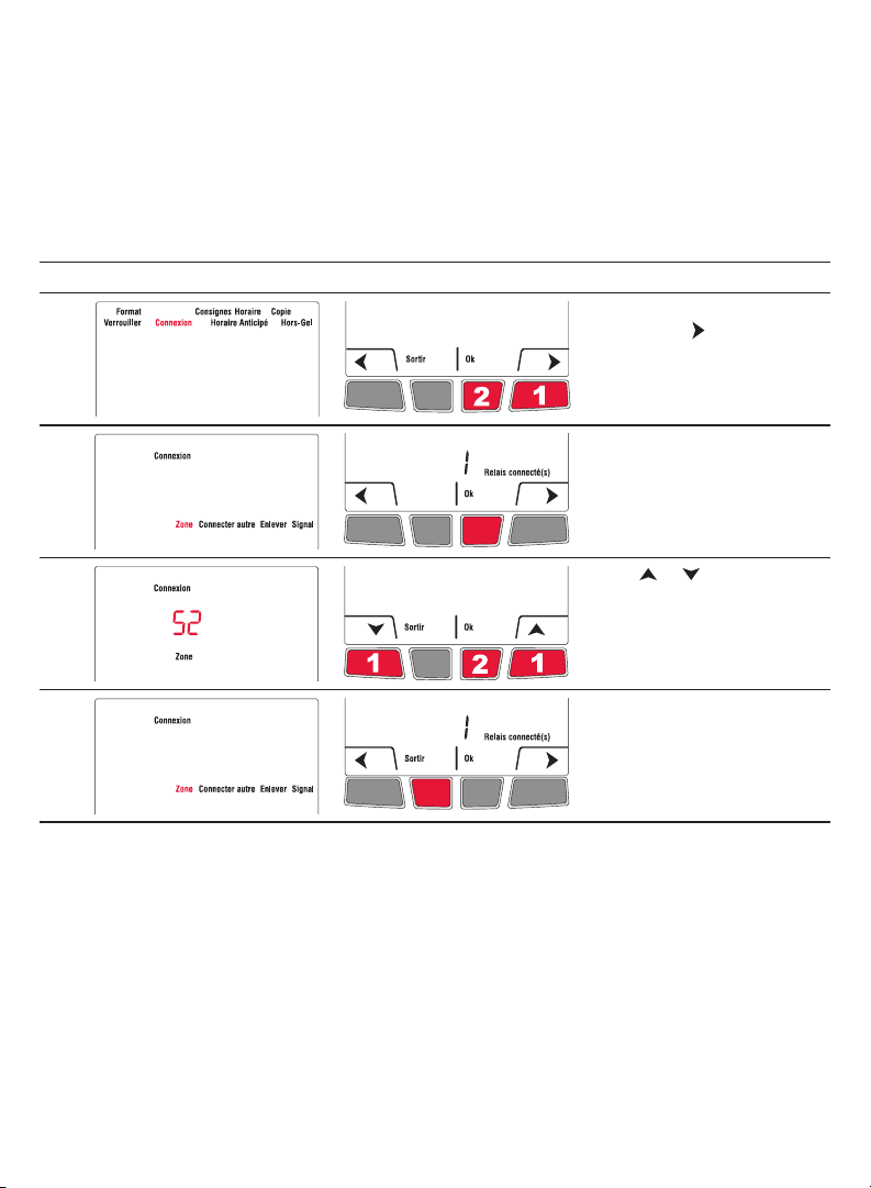
Zone
Le nom de la zone sert à identifier le thermostat sur la télécommande. Par défaut, le nom
de la zone du thermostat est Thermostat (zone 52). Si vous avez une télécommande et
plus d’un thermostat sans fil, changer le nom de la zone du thermostat afin de l’identifier
des autres thermostats. Par exemple, si le thermostat est dans le salon, placer la zone à
31.
# Affichage Boutons Étapes
1
A partir du menu de
l’installateur, appuyer
sur pour sélectionner
Connexion et appuyer sur
Ok.
2
3
4
Appuyer sur OK pour
sélectionner Zone.
Appuyer sur ou pour
sélectionner le nom de
la zone (voir la page 17).
Appuyer sur OK.
Appuyer sur Sortir une fois
pour revenir au menu de
l’installateur ou 2 fois pour
revenir à l’écran d’accueil.
69-2472EF—01 16
Page 43

EConnectMC TA7210
Liste des noms de zone
Zone Nom Zone Nom Zone Nom Zone Nom
1 Basement 16 Exercise Room 30 Library 44 Porch
2 Bathroom 17 Family Room 31 Living Room 45 Rec Room
3 Bathroom 1 18 Fireplace 32 Lower Level 46 Sewing Room
4 Bathroom 2 19 Foyer 33 Master Bath 47 Spa
5 Bathroom 3 20 Game Room 34 Master Bed 48 Storage Room
6 Bedroom 21 Garage 35 Media Room 49 Studio
7 Bedroom 1 22 Great Room 36 Music Room 50 Sun Room
8 Bedroom 2 23 Guest Room 37 Nursery 51 Theater
9 Bedroom 3 24 Gym 38 Office 52 Thermostat
10 Bedroom 4 25 Kid’s Room 39 Office 1 53 Upper Level
11 Boat House 26 Kitchen 40 Office 2 54 Utility Room
12 Bonus Room 27 Kitchen 1 41 Pantry 55 Walk In Closet
13 Computer Room 28 Kitchen 2 42 Play Room 56 Wine Cellar
14 Den 29 Laundry Room 43 Pool Room 57 Workshop
15 Dining Room
Horaire anticipé
Disponible seulement lorsque vous utiliser le thermostat en mode programmable.
Lorsque la fonction Horaire Anticipé est activée, le thermostat “apprend” combien de
temps il faut à votre appareil de chauffage pour atteindre la température programmée.
Le thermostat déterminera ensuite quand démarrer le chauffage afin que la température
désirée soit atteinte à l’heure désirée. Le thermostat évalue, sur une base quotidienne,
l’heure de démarrage du chauffage en se basant sur le résultat de la journée précédente.
Lorsque la fonction est désactivée, le thermostat démarre le chauffage à l’heure réglée.
Pour désactiver la fonction de l’horaire anticipé, procéder comme suit :
# Affichage Boutons Étapes
1
2
17 69-2472EF—01
A partir du menu de
l’installateur, appuyer sur
pour sélectionner Horaire
Anticipé et appuyer sur Ok.
Appuyer sur ou pour
mettre à Non et appuyer
sur Ok.
Page 44

Guide d’installation
Hors-gel
Lorsque cette fonction est utilisée, le MIM maintiendra la température ambiante à 13 °C
(55 °F) s’il perd la communication avec le thermostat ou si la sonde du thermostat est
défectueuse.
Garder la protection activée sauf si le MIM est installé dans une pièce différente de celle
de l’appareil de chauffage.
Pour enlever la fonction Hors-gel, procéder comme suit :
# Affichage Boutons Étapes
1
A partir du menu de
l’installateur, appuyer sur
pour sélectionner Hors-Gel
et appuyer sur Ok.
2
Appuyer sur ou pour
mettre à Non. Appuyer sur
Ok.
Vérication du système
1 A partir de l’écran d’accueil, appuyer sur pour placer la température de consigne
d’au moins 2° supérieure à la température ambiante de la pièce. Appuyer sur
Temporaire.
2 Attendre que Chauffe s’affiche sur le thermostat.
3 Vérifier si l’appareil de chauffage devient chaud.
4 Appuyer sur Annuler pour retourner le thermostat à son mode précédent.
69-2472EF—01 18
Page 45
EConnectMC TA7210
6 Installation du thermostat et de la sonde extérieure
Suivre les directives ci-dessous pour installer le thermostat :
• Ne PAS installer le thermostat à un endroit où il risque d’être exposé à l’eau ou à la pluie.
• Éviter les endroits où il y a des courants d’air (le haut d’un escalier, une sortie d’air),
des points d’air stagnant (derrière une porte), des rayons directs du soleil, des tuyaux
dissimulés ou une cheminée.
• Pour une nouvelle installation. placer le thermostat à environ 1,5 mètre (5 pieds) du sol.
• Installer le thermostat sur une cloison intérieure faisant face à l’appareil de chauffage.
• Garder les ouvertures d’aération du thermostat propres et dégagées en tout temps.
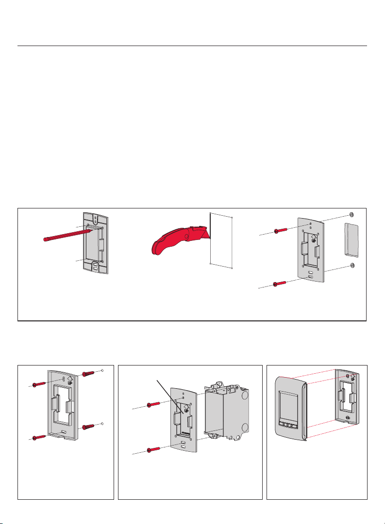
Deux plaques de montage sont fournis pour installer le thermostat sur le mur ou sur une
boîte de jonction. Utilisez la méthode A pour une apparence amincie. Optez pour la
méthode B si vous préférez de ne pas faire une ouverture dans le mur. La méthode C
doit être utilisée lorsque le thermostat est installé sur une boîte de jonction.
Encastrer au mur (méthode A)
Marquer les quatre coins et les
joindre pour créer un contour
rectangulaire.
Installer au mur
(méthode B)
Fixer la plaque de
montage au mur en
utilisant les chevilles et
vis fournies.
19 69-2472EF—01
Couper le long du contour
pour créer une ouverture dans
le mur.
Installer sur une boite de
jonction (méthode C)
Plaque de montage sans ouverture
Fixer la plaque de montage sur une
boîte de jonction en utilisant les vis
mécaniques fournies.
Fixer la plaque de montage au
mur en utilisant les chevilles et
vis fournies.
Installer la façade
Terminer l’installation du
thermostat en appuyant la
façade contre la plaque de
montage.
Page 46

Guide d’installation
Installer la sonde extérieure (facultatif)
Installer la sonde à la verticale
sur un mur extérieur, au moins
6 pouces au-dessous de tout
surplomb. Choisir un emplacement
à l’abri des rayons du soleil.
Installer la sonde dans son support,
avec son dos faisant face au mur.
Codes d’erreur
Affichage Description
LO
HI
- E128
E129
E130
E134
E137
E138
E152
La température ambiante est inférieure à 0°C (32°F).
La température ambiante est supérieure à 60°C (140°F).
La lecture de température est non disponible ou la sonde extérieure est défectueuse.
Le réseau sans fil doit être réconfiguré.
Tentative de configuration de dispositifs incompatibles.
Adresse invalide. Contacter le service à la clientèle.
Signal trop faible. Déplacer le dispositif sans fil à un autre endroit et essayer à
nouveau.
Le nombre maximal de dispositifs est dépassé.
S’assurer que le voyant de connexion de l’adaptateur sans fil clignotent et que le
thermostat ou la télécommande sont à 2 pieds et plus de l’adaptateur sans fil.
Ordre incorrect. S’assurer de relier le MIM au bon thermostat.
69-2472EF—01 20
Page 47

EConnectMC TA7210
Vérifier l’intensité du signal entre le MIM et le thermostat
Si vous avez plusieurs MIM reliés au thermostat, la valeur affichée est celle entre le
thermostat et le premier MIM relié au thermostat. L’intensité du signal varie entre 0 (aucun
signal) à 10 (maximum).
# Affichage Boutons Étapes
1
A partir de l’écran d’accueil,
appuyer et maintenir le
bouton du centre droit
pendant 5 secondes.
2
3
4
Appuyer sur pour
sélectionner Connexion et
appuyer sur Ok.
Appuyer sur pour
sélectionner Signal et
appuyer sur Ok.
L’intensité du signal est
affichée. Appuyer sur Sortir
deux fois pour revenir au
menu de l’installateur ou trois
fois pour revenir à l’écran
d’accueil.
Remplacement des dispositifs sans fil
Thermostat
Pour remplacer le thermostat, installer des piles dans le nouveau thermostat (voir la
page 7) et le relier au réseau sans fil (voir la page 8). Pour personnaliser le thermostat,
voir les pages 11-18.
Si vous avez plusieurs MIMs reliés à l’ancien thermostat, vous pouvez relier le thermostat à
partir de n’importe quel des MIMs.
21 69-2472EF—01
Page 48

Guide d’installation
Télécommande ou sonde extérieure
Pour remplacer la télécommande ou la sonde extérieure, installer des piles dans le
nouveau dispositif (voir la page 7) et le relier au réseau sans fil (voir la page 10).
Si vous avez plusieurs MIMs reliés au même thermostat, vous pouvez relier la télécommande
ou la sonde extérieure à partir de n’importe quel des MIMs.
Si vous avez plusieurs thermostats sans fil, relier la télécommande ou la sonde extérieure à
partir d’un MIM de chacun des thermostats.
Module d’interface avec le matériel (MIM)
Si vous avez une télécommande :
1 Appuyer environ 3 secondes sur l’espace vierge (ou la flèche,
selon le cas) dans le coin inférieur de l’écran jusqu’à ce que
l’affichage change.
2 Appuyer sur le bouton REMOVE (enlever), puis sur YES (oui).
Si un seul MIM est relié au thermostat :
Retirer le MIM défectueux, installer un nouveau (voir pages 3 à 6) et procéder comme suit:
1 Vérifier si le thermostat affiche 0 Relais connecté(s) tel qu’illustré à la
droite. Si oui, passer à l’étape 5.
2 A partir de l’écran d’accueil, appuyer et maintenir le bouton du centre
droit pendant 5 secondes.
3 Appuyer sur pour sélectionner Connexion et appuyer sur Ok.
4 Appuyer sur pour sélectionner Enlever et appuyer sur Ok. Le
thermostat affichera 0 Relais connecté(s).
5 Suivre les étapes aux pages 7-11 pour créer un nouveau réseau avec le nouveau EIM.
Si plusieurs MIMs sont reliés au thermostat: :
Suivre la procédure ci-dessous pour identifier les MIM(s) défectueux et de
rétablir tous les liens :
1 Retirer le couvercle de l’antenne de chacun des MIMs dans le réseau :
placer un doigt sur le dessus et un autre doigt sur le dessous (tel
qu’indiqué par les flèches rouges), appuyer sur le couvercle et tirer.
2 Appuyer, pendant 10 secondes, sur le bouton de connexion de n’importe quel MIM
dont le voyant vert est allumé. Répéter l’étape jusqu’à ce que le voyant vert de
chaque MIM du réseau soit éteint.
3 Vérifier si le thermostat affiche 0 Relais connecté(s) tel qu’indiqué à la droite. Si
oui, passer à l’étape 7.
4 A partir de l’écran d’accueil, appuyer et maintenir le bouton du centre
droit pendant 5 secondes.
5 Appuyer sur pour sélectionner Connexion et appuyer sur Ok.
6 Appuyer sur pour sélectionner Enlever et appuyer sur Ok. Le
thermostat affichera 0 Relais connecté(s).
7 Suivre les étapes aux pages 7-11 pour créer un nouveau réseau. Vous
saurez qu’un MIM est défectueux si son voyant devient rouge ou le
thermostat affiche un code d’erreur lorsque vous essayez de relier le MIM au réseau.
Le remplacer avant de continuer à relier les autres MIMs.
Appuyer
ici
69-2472EF—01 22
Page 49

EConnectMC TA7210
Caractéristiques techniques et pièces de rechange
Thermostat
Plage de température de consigne : 5 °C - 30 °C (41 °F - 86 °F)
Résolution de température de consigne : 0,5 °C (1 °F)
Plage de température affichée : 0 °C - 40 °C (32 °F - 104 °F)
Résolution de température affichée : 0.5 °C (1 °F)
Cycle de chauffage : 15 minutes
Programmation : 5-2 jours, 7 jours, 1 jour ou non programmable
Température ambiante de service
Thermostat : 0 °C - 50 °C (32 °F - 122 °F)
Télécommande : 0 °C - 48,9 °C (32 °F - 120 °F)
MIM (relais) : -20 °C - 60 °C (-4 °F - 140 °F)
MIM (antenne) : -20 °C - 60 °C (-4 °F - 140 °F)
Sonde extérieure : -40 °C - 60 °C (-40 °F - 140 °F)
Humidité relative de service
Thermostat : 5% - 90% (sans condensation)
Télécommande : 5% - 90% (sans condensation)
MIM (relais) : 5% - 95% (sans condensation)
MIM (antenne) : 5% - 95% (sans condensation)
Sonde extérieure : 0% - 100% (condensation)
Encombrement (hauteur, largeur, profondeur)
Thermostat : 130 x 82 x 29 mm (5.13 x 3.22 x 1.14 po)
MIM (relais) : 73 x 63 x 29 mm (3.03 x 2.49 x 1.28 po)
MIM (antenne) : 71 x 62 x 33 mm (2.89 x 2.63 x 1.16 po)
Sonde extérieure : 127 x 89 x 43 mm (5.00 x 3.50 x 1.68 po))
Caractéristiques électriques (MIM)
Alimentation : 100-240 Vca, 50/60 Hz
Charge minimale : 0.4 A (résistive seulement)
Charge maximale : 12.5 A (résistive seulement)
Accessoires et pièces de rechange
Article Numéro de pièce
Module d’interface avec le matériel (MIM) ATM100-SPK
Télécommande REM5000R1001
Sonde extérieure C7089R1013
Couvercle d’antenne (blanc) 50055751-002
Couvercle d’antenne (amande) 50055751-004
23 69-2472EF—01
Page 50

Guide d’installation
Information sur la réglementation
Déclaration de conformité à la FCC (partie 15,19) (États-Unis seulement)
Cet appareil est conforme à la Partie 15 des règles de la FCC. Le fonctionnement de ce système
est assorti aux deux conditions suivantes :
1) L’appareil ne peut causer d’interférences nuisibles, et
2) L’appareil doit accepter les interférences reçues, y compris celles qui pourraient nuire à son
fonctionnement.
Avis de la FCC (partie 15,21) (États-Unis seulement)
Toute modification qui n’est pas autorisée expressément par la partie responsable de la conformité
de l’appareil aux règles en vigueur pourrait rendre l’utilisateur inapte à faire fonctionner le matériel.
Déclaration sur l’interférence selon la FCC (partie 15,105 (b)) (États-Unis seulement)
Ce dispositif a été testé et déclaré conforme aux normes spécifiées dans la partie 15 des
règlements de la FCC (Federal Communications Commission) concernant les dispositifs numériques
de classe B. Ces limites sont conçues pour offrir une protection raisonnable contre les interférences
nocives pouvant survenir lorsque le produit est utilisé dans un environnement résidentiel. Ce
dispositif produit, utilise et émet de l’énergie radioélectrique qui peut perturber les communications
radio s’il n’est pas installé et utilisé conformément aux instructions du fabricant. Toutefois, rien ne
garantit qu’il n’y aura pas d’interférences dans une installation donnée. Si l’appareil produit des
interférences qui nuisent à la réception radio ou télé, ce qu’on peut déterminer en mettant l’appareil
en service et hors service, l’utilisateur est invité à corriger la situation de l’une ou l’autre des façons
suivantes :
•Réorienteroudéplacerl’antennederéception.
•Augmenterl’espacequiséparel’appareildurécepteur.
•Brancherl’appareilàuneprisefaisantpartied’uncircuitdifférentdeceluidurécepteur.
•Consulterundétaillantoutechnicienradio-téléd’expériencepourobtenirdel’aide.
MIM, thermostat et sonde extérieure
Pour être conformes aux limites d’exposition aux radiofréquences établies par la FCC et Industrie
Canada pour le grand public/l’exposition non contrôlée, la ou les antennes employées par le
transmetteur doivent être installées à au moins 20 cm de distance de toute personne et ne peuvent
être situées au même endroit qu’une autre antenne ou un autre transmetteur ou fonctionner
conjointement avec une autre antenne ou un autre transmetteur.
Télécommande
Le transmetteur portatif et son antenne sont conformes aux limites d’exposition aux
radiofréquences établies par la FCC et Industrie Canada pour le grand public/l’exposition non
contrôlée. Cet appareil ne doit pas être placé au même endroit qu’une autre antenne ou un autre
transmetteur ni fonctionner conjointement avec d’autres antennes ou transmetteurs.
Article 7.1.3 de CNR-GEN
Le fonctionnement de ce système est assorti aux deux conditions suivantes :
1) L’appareil ne peut causer d’interférences nuisibles, et
2) L’appareil doit accepter les interférences reçues, y compris celles qui pourraient nuire à son
fonctionnement.
Article 7.1.2 de RSS-GEN
Conformément à la législation d’Industrie Canada, l’émetteur radioélectrique ne peut fonctionner
qu’avec une antenne de type et de gain maximum (ou moins) approuvés pour le transmetteur par
Industrie Canada. Pour réduire le potentiel d’interférence radioélectrique pour d’autres utilisateurs, le
type d’antenne et son gain doivent être choisis pour que la puissance isotrope rayonnée équivalente
(PIRE) soit limitée à celle juste requise pour obtenir une bonne communication.
69-2472EF—01 24
Page 51

Page 52

Besoin d’aide?
Pour obtenir de l’aide sur ce produit, veuillez consulter le www.aubetech.com,
ou joindre sans frais le service à la clientèle d’Honeywell au 1 800 831-2823.
Solutions de régulation et d’automatisation
Honeywell International Inc.
1985 Douglas Drive North
Golden Valley, MN 55422
http://customer.honeywell.com
69-2472EF-01
06-2011
© 2011 Honeywell International Inc.
® Marque déposée aux É.-U.
Tous droits réservés.
Imprimé aux É.-U.
Honeywell Limited
705 Montrichard
Saint-Jean-sur-Richelieu, Québec, J2X 5K8
www.aubetech.com
 Loading...