

Page 1
62-0255-09
T775U Series 2000 Electronic
Stand-Alone Controller
INSTALLATION INSTRUCTIONS
PRODUCT DESCRIPTION
The T775 electronic stand-alone controllers are the next
generation of universal controls capable of remote
sensing of temperature, humidity, pressure, etc. and
providing switched and proportional outputs to various
types of loads. A built-in time clock is standard.
The T775U controller allows a wide range of sensors to
be configured. Humidity, pressure, temperature, or any
0-5 Vdc, 0-10 Vdc, or 4-20 mA input is supported.
A Reset function is available where the Sensor B
temperature (e.g. outside temperature) is used to provide
reset control for Sensor A (e.g. humidity). For example,
as the outside temperature gets colder, the setpoint can
automatically be adjusted to prevent condensation.
IMPORTANT
The T775U is an operating control, not a limit or
safety control. If used in applications requiring
safety or limit controls, a separate safety or limit
control device is required.
Table 1. T775U Controller Configurations.
Controller
a
Model
T775U2006
T775U2016 N/A Yes 2 2
a
The T775U includes a digital input for use with the disable or setback option.
b
The modulating (analog) outputs may be 4-20 mA, 0-10 Vdc, 2-10 Vdc, or Series 90 selectable.
c
For the H775C1004, H775D1003, and H775E1002 model replacement, the T775U only partially replaces the function
of these devices. Check application for suitability.
d
For the sensor inputs, Sensor A can be 0-10Vdc, 4-20mA, or a standard temperature input. Sensor B is a standard
temperature sensor input only. Sensor B is used only for reset on the T775U2006.
e
The T775U2016 can control Sensor A (universal) and Sensor B (temperature) independently, like other standard
T775 controllers.
Description Replaces
H775A1006
H775A1022
Universal:
Humidity,
Pressure,
Temperature,
etc.
H775A1048
H775A1063
H775B1005
H775C1004
H775D1003
H775E1002
Output
c
c
c
SPDT
Relay
Reset
Outputs
Ye s 2 2
Analog
(Mod)
Outputs
b
Sensor
Inputs
d
2
e
2
Nbr of
Sensors
Included Enclosure
None NEMA 1
None NEMA 1
Page 2

T775U SERIES 2000 ELECTRONIC STAND-ALONE CONTROLLER
Temperature Sensorsa (Sensor A or B)
The controller accepts 1,097 Ohms PTC at 77°F (25°C):
• 50021579-001 – Standard sensor (included with all
models except NEMA 4X models)
• T775-SENS-WR – Water resistant with 5 foot leads
(included with NEMA 4X models)
• T775-SENS-WT – Watertight with 6 foot lead
• T775-SENS-OAT – Outdoor air temperature sensor
• C7031D2003 – 5 inch immersion sensor with wiring
box (use immersion well; P/N 50001774-001)
• C7031J2009 – 12 foot duct averaging sensor with
wiring box
• C7046D1008 – 8 inch duct probe with mounting flange
• C7100D1001 – 12 inch fast response, duct averaging
sensor with flange
• C7130B1009 – Room mount sensor
Differential Pressure Sensors
(Sensor A only)
P7640A and PWT pressure transducer models with
selectable pressure ranges can be used.
The controller accepts pressure sensors with a signal
output of 0-10 Vdc or 4-20 mA for any output range within
the following ranges (the minimum and maximum for the
sensor output range can be adjusted within the following
limits):
• -500 to 500 PSI
• -30.0 to 30.0 inches w.c.
• -3,000 to 3,000 Pa
• -3,000 to 3,000 kPa
Humidity Sensors (Sensor A only)
The controller accepts 0-10 Vdc or 4-20 mA input with a
range of 0-100%.
H7625, H7635, and H7655 models (available in 2, 3, and
5% RH accuracy) can be used.
CO2 Sensors
The controller accepts a 0-10 Vdc or 4-20 mA input from
C7232 and C7632 CO
units.
sensors and is settable in PPM
2
Universal Sensors (Sensor A only)
The controller accepts 0-5 Vdc, 0-10 Vdc or 4-20 mA input
for temperature, pressure, humidity CO
be programmed in units of °F, °C, %, Pa, kPa, PSI, In
W.C., PPM, or may be unitless (none).
The PPM range is 0 to 9990.
Choosing none for units, results in no units being
displayed on the home screen. If no unit is specified the
range is -9999 to +9999.
Actuators
For more information on compatible actuators or other
Honeywell products, such as dampers and valves, go to
www.customer.honeywell.com
select Product Selection Tool under Products.
• Spring return models: ML6425, ML7425, MS4105,
MS4110, MS4120, MS7505, MS7510, MS7520,
MS8105, MS8110, MS8120
• Non-spring return models: ML4161, ML6174, ML7161,
MN6105, MN1010, MN7505, ML7164, MN8810
, etc. They may
2
. From the home page
Accessories
• 107324A – Bulb Holder, duct insertion
• 107408 – Heat Conductive Compound, 4 ounce
• 50001774-001 – Immersion Well, stainless steel 304,
1/2 in. threading
Product Changes
Below are the changes to T775U models star ting with
Series 3 (March 2009). Series 3 can be identified by the
sideways 3 after the part number on the device label.
1. Setpoint and Enable options added to the DI
options.
2. 0-5 Vdc sensor inputs are now available (for both
models).
3. MIN ON time added.
4. HIDE option added to MOD1 and MOD2 (to hide
them on the home screen).
5. PPM and None added to sensors’ unit of measure.
6. With the new T775U2016 model, all outputs can be
controlled to Sensor A or Sensor B. The
T775U2006 model controls only to Sensor A.
a
See form 62-0265 – Temperature Sensors for the T775
Series 2000 Stand-alone Controller
62-0255—09 2
Page 3
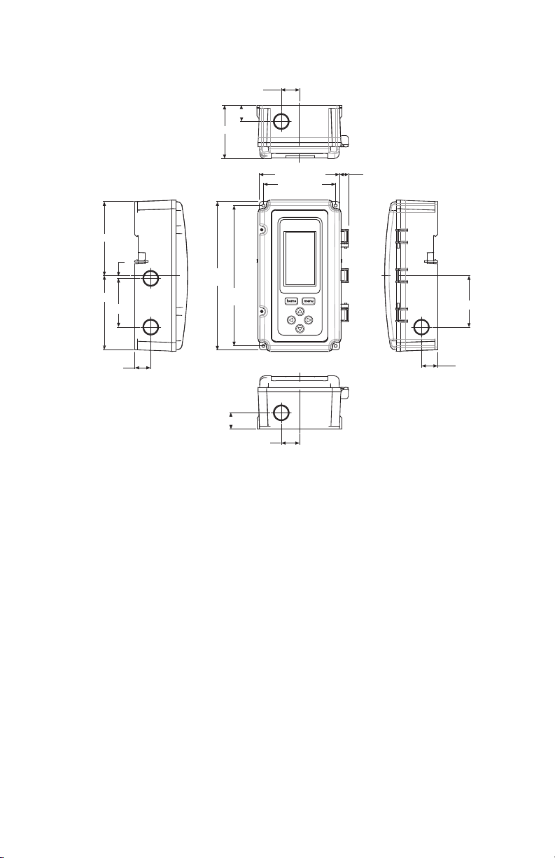
Controller Dimensions
T775U SERIES 2000 ELECTRONIC STAND-ALONE CONTROLLER
1 (25.5)
7/8 (22.5)
2 15/16 (74)
LEFT RIGHT
4 1/16 (103.4)
1/64 (3.8)
8 5/32
(207.1)
4 1/16 (103.4)
2 11/16 (68.1)
7/8 (22.5)
7 23/32
(196)
7/8 (22.5)
Fig. 1. T775U Dimensions in inches (mm).
BEFORE INSTALLATION
Review the “Specifications” on page 38 before
installing the controller.
When Installing This Product
1. Read these instructions carefully. Failure to follow
them could damage the product or cause a hazardous condition.
2. Check ratings given in instructions and on the product to ensure the product is suitable for your application.
3. Installer must be a trained, experienced service
technician.
4. After installation is complete, check out product
operation as provided in these instructions.
INSTALLATION AND SETUP
The following installation procedures are typically
performed in the order listed:
1. Mounting — see “Mounting” below.
2. Wiring — see “Wiring” on this page.
3. Checkout — see page 10.
Interface and Programming overview – see page 11.
4.
5. Setup – see page 14.
TOP
4 13/32 (112.1)
3 31/32 (101)
FRONT VIEW
1 (25.5)
BOTTOM
6.
Programming the Controller with no Reset – see page 26
or
Programming the Controller with Reset – page 29.
7. Scheduling (optional)— see page 34.
Additional topics are:
• Sensor calibration begins on page 11.
• Interface overview begins on page 11.
• Summary menu begins on page 38.
• Troubleshooting begins on page 38.
1/2 (12.4)
MOUNTING
This section describes the mounting procedures for the
controller and temperature sensor(s).
Controller Mounting
IMPORTANT
Avoid mounting in areas where acid fumes or
other deteriorating vapors can attack the metal
parts of the controller circuit board, or in areas
where escaping gas or other explosive vapors
are present.
IMPORTANT
The controller must be mounted in a position that
allows clearance for wiring, servicing, and
removal.
2 13/16 (71.8)
7/8 (22.5)
M24546
3 62-0255—09
Page 4

T775U SERIES 2000 ELECTRONIC STAND-ALONE CONTROLLER
CAUTION
SENSOR
PLACED
IN WELL
IMMERSION
WELL
1/2 NPT
USE HEAT
CONDUCTIVE
COMPOUND
M24379
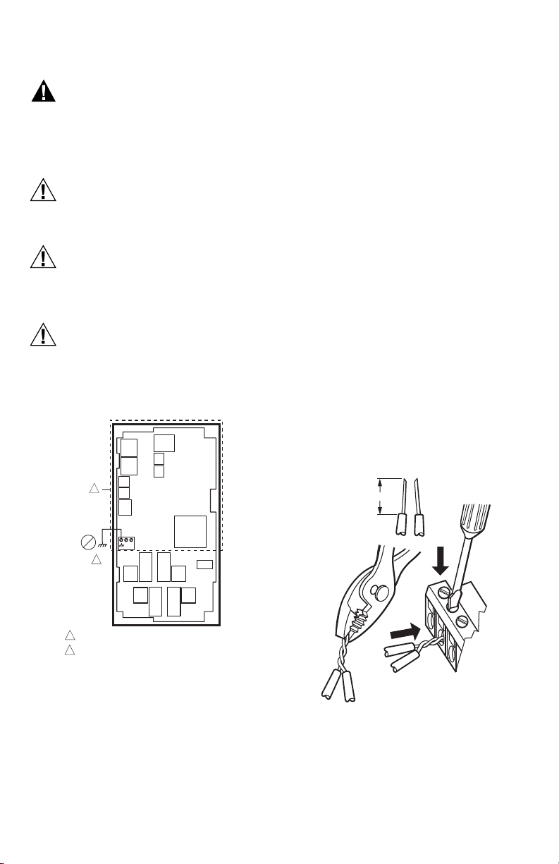
Use a screwdriver to pry out only the knockouts that you
will use.
If mounting on DIN rail, be sure to remove the knockouts
before mounting. See “Controller Wiring” on page 7 and
Fig. 12 on page 9 for recommended knockout usage and
locations. If you do not use an opened knockout be sure
to cover it.
Mount the controller on any convenient interior location
using the four mounting holes provided on the back of the
enclosure using #6 or #8 screws (screws are not provided
and must be obtained separately). Use controller
dimensions in Fig. 1 on page 3 as a guide.
The controller may be mounted in any orientation.
However, mounting in the orientation shown in Fig. 1 on
page 3 permits proper viewing of the LCD display and use
of the keypad.
Humidity, Pressure, and Universal Sensor(s) Mounting and Location
These sensors may be mounted on a wall or panel. Follow
the installation instructions specific to the sensor you are
installing.
Temperature Sensor(s) Mounting and Location
Temperature sensors may be located up to 1,000 feet
(304 m) from the T775U controller. See Table 4 on
page 11 for calibration guidelines.
The sensors may be mounted on a wall or panel for
sensing space temperature, strapped to a pipe or inserted
in an immersion well (see Fig. 2) for hot or cold water
sensing, or taped to a standard cap or bulb holder for duct
air sensing. To prevent moisture or condensation entering
the sensor through the lead wire holes, mount the sensor
with the lead wires exiting the bottom of the sensor.
NOTES:
1. The included sensor is not designed for very
wet applications. For immersion applications,
an immersion well is used.
2. Heat conductive compound must be used in
immersion wells.
3. See “Temperature Sensors (Sensor A or B)”
on page 2 for this type of installation.
Fig. 2. Sensor inserted in immersion well.
NOTE: Multiple sensors may be parallel-series wired
to sense average temperatures in large
spaces. See Fig. 3 on page 5.
WIRING
All wiring must comply with applicable electrical codes
and ordinances, or as specified on installation wiring
diagrams. Controller wiring is terminated to the screw
terminal blocks located inside the device.
The remainder of this section describes the sensor wiring
and the T775U controller wiring.
Wiring Connections Access
To access the wiring connections, remove the two screws
on the left side of the enclosure and gently swing open the
top. Be careful to not stress the ribbon cables that connect
the keypad and LCD display to the controller circuit board.
Temperature Sensor Wiring
Electrical Shock Hazard.
Can short equipment circuitry.
Make sure that metal tube of sensor does not
short against T terminals in wall-mounted case.
IMPORTANT
Poor wiring practices can cause erratic readings
from the sensor. Avoid the following to ensure
proper operation:
• Do not route the temperature sensor wiring with
building power wiring.
• Do not locate the temperature sensor wiring next
to control contactors.
• Do not locate the temperature sensor wiring near
electrical motors.
• Do not locate the temperature sensor wiring near
welding equipment.
• Make sure good mechanical connections are
made to both the sensor and the controller.
• Do not mount the sensor with the lead wire end
pointing up in an area where condensation can
occur.
If any of the above conditions cannot be avoided,
use shielded cable.
NOTE: Each T775 controller must be wired to its own
sensor(s). However, a benefit of the T775
controller’s accuracy is that there is no more
than a 2°F differential between any two T775
controllers.
Reset Temperature Control
If you are implementing two-sensor reset control, Sensor
A must always be the controlled temperature and Sensor
B must always be the controlling temperature.
For example, in a reset control based on outside
temperature, Sensor A must be the inside sensor and
Sensor B must be the outside sensor.
Multiple Parallel Temperature Sensors
Multiple sensors can be parallel-series wired to sense
average temperatures in large spaces. To maintain control
accuracy, the number of sensors to be parallel-series
wired must be of the n
See Fig. 3.
2
power (for example, 4, 9, 16, etc.).
62-0255—09 4
Page 5
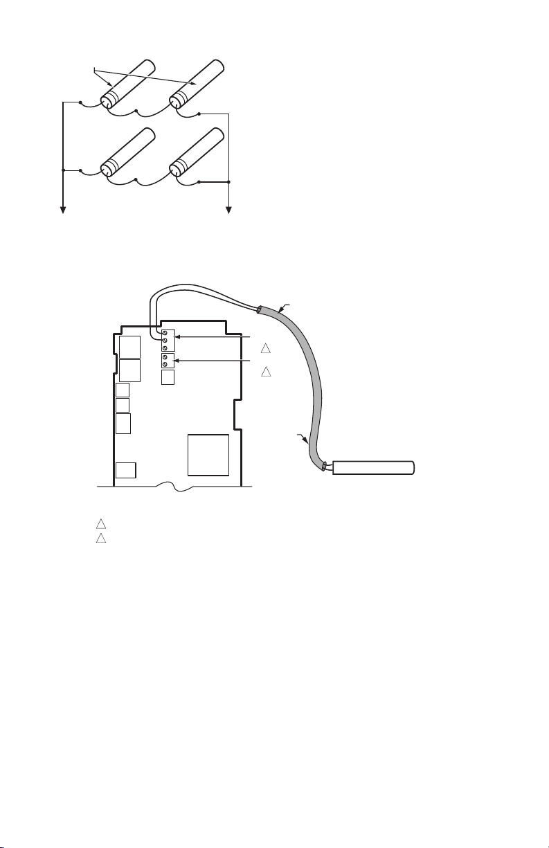
Fig. 3. Parallel-series wiring of sensors.
TO T775 CONNECTIONS (SENSOR A) OR (SENSOR B).
SENSORS
M24548
M24549A
SENSORS A AND B ARE POLARITY INSENSITIVE WHEN USING A 1097 OHM PTC TEMPERATURE SENSOR.
SENSOR B IS USED ONLY IN RESET APPLICATIONS ON THE T775U20006.
1
SHIELDED
CABLE
SHIELDED
CABLE
SENSOR
NOTE: SHIELDED CABLE MUST BE
CONNECTED TO A SEPARATE EARTH
GROUND.
HOWEVER, DO NOT GROUND
SHIELDED CABLE AT SENSOR END.
NOTE: TO MINIMIZE NOISE PICKUP,
MAKE SENSOR CONNECTION FROM
SHIELDED CABLE AS CLOSE AS
POSSIBLE TO SENSOR BODY.
T
T
T
T
SENSOR A
SENSOR B
1
2
2
T775U SERIES 2000 ELECTRONIC STAND-ALONE CONTROLLER
Temperature Sensor Wire Type and Size
Temperature sensors use standard AWG 18/2 unshielded
wire. For cable runs greater than 25 feet or where
electrical interference may be a problem, shielded cable is
recommended. See Fig. 4.
Refer to “Temperature Sensor Calibration” on page 11 for
wire size selection where cable runs are longer than
25 feet.
Fig. 4. Sensor Wiring — 2-wire shielded cable connection from Sensor A to temperature sensor.
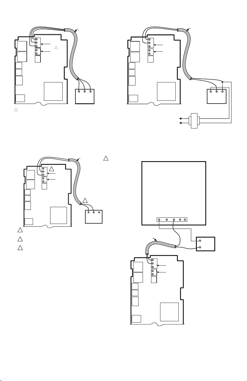
Humidity, Pressure, and Universal Sensor Wiring
Sensors with a 0-5 Vdc, 0-10Vdc or 4-20mA input to the
T775U must be wired to the Sensor A terminal. Sensor B
is used only as a temperature input.
Sensors use standard AWG 18 unshielded wire. For cable
runs greater than 25 feet, shielded cable is
recommended.
The sensors in Fig. 5 – 8 beginning on page 6 are
examples and illustrate voltage and current wiring for 3wire and 2-wire sensors to the Sensor A terminal. For
terminal wiring details, see Fig. 11 and Table 2 on page 8.
Other sensors are supported. See sensor descriptions on
page 2.
NOTES:
5 62-0255—09
1. Other transmitters can be wired in the same
manner. For example, the 0-10Vdc wiring
shown in Fig. 5 on page 6 with the H76XX
sensor can also be done with the P7640 or
any other transmitter.
2. The T775U V terminal outputs 18 Vdc.
Page 6
T775U SERIES 2000 ELECTRONIC STAND-ALONE CONTROLLER
M24551
S
C
NOTES:
1. SHIELDED CABLE MUST BE
CONNECTED TO A SEPARATE
EARTH GROUND. HOWEVER,
DO NOT GROUND SHIELDED
CABLE AT SENSOR END.
2. TO MINIMIZE NOISE PICKUP,
MAKE SENSOR CONNECTION
FROM SHIELDED CABLE AS
CLOSE AS POSSIBLE TO
SENSOR BODY.
EXAMPLE OF
P7640A
PRESSURE
SENSOR;
0-10 VDC
CONNECTION
SENSOR A
SENSOR B
T
T
SHIELDED CABLE
PWR
OUT
COM
C
S
V
L1
(HOT)
L2
24 VAC
SHIELDED CABLE
C
S
SENSOR A
V
1
T
SENSOR B
T
1
THE T775U WILL ONLY ACCEPT 0-10 VDC AND 4-20 MA SENSORS.
IF REPLACING AN H775 CONTROLLER THAT USES A C7600B OR OTHER
2-10 VDC SENSOR, THE SENSOR MUST BE REPLACED. REPLACE THE
C7600B2008 SENSOR (2-10VDC OUTPUT) WITH THE H7655A1001
(0-10 VDC OUTPUT) SENSOR. THE H7655A1001 SENSOR USES THE SAME
ENCLOSURE STYLING AND WIRING AS THE C7600B.
Fig. 5. Sensor Wiring — 3-wire shielded cable
connection from Sensor A to 0-10 Vdc sensor
(H76xx humidity sensor shown).
NOTES:
1. SHIELDED CABLE MUST BE
CONNECTED TO A SEPARATE
EARTH GROUND. HOWEVER,
DO NOT GROUND SHIELDED
CABLE AT SENSOR END.
2. TO MINIMIZE NOISE PICKUP,
MAKE SENSOR CONNECTION
FROM SHIELDED CABLE AS
CLOSE AS POSSIBLE TO
SENSOR BODY.
CSV
EXAMPLE OF
VO
GND
VIN
H76XX HUMIDITY
SENSOR;
0-10 VDC
CONNECTION
M24550
Fig. 7. Sensor Wiring — 2-wire shielded cable
connection from Sensor A to a 0-10 Vdc sensor
using separate transformer.
SHIELDED CABLE
C
3
S
SENSOR A
V
T
SENSOR B
T
2
V
1
SHIELDED CABLE MUST BE CONNECTED TO A SEPARATE EARTH GROUND.
DO NOT GROUND SHIELDED CABLE AT SENSOR END.
TO MINIMIZE NOISE PICKUP, MAKE SENSOR CONNECTION FROM SHIELDED
2
CABLE AS CLOSE AS POSSIBLE TO SENSOR BODY.
THE T775 HAS AN INTEGRAL LOAD OF 500 OHMS WHICH RESULTS IN A
3
10V DROP AT 20MA. TO USE 4-20MA LOOP POWERED WIRING, THE SENSOR
MUST BE CAPABLE OF OPERATION WITH 8V OR LESS ACROSS ITS TERMINAL.
Fig. 6. Sensor Wiring — 2-wire shielded cable
connection from 4-20 mA sensor to
T775 controller (loop powered wiring).
62-0255—09 6
PWR
OUT
1
S
COM
M24890C
EXAMPLE OF P7640A 4-20 MA SENSOR CONNECTION
PWR ZEROCOMOUT
12-30 VDC
SHIELDED CABLE
C
S
V
T
T
Fig. 8. Sensor Wiring — 2-wire 4-20mA sensor input
to T775 controller using a separate (Vdc only)
S
SENSOR A
SENSOR B
transformer.
POWER SUPPLY
+
–
C
NOTES:
1. SHIELDED CABLE MUST BE
CONNECTED TO A SEPARATE
EARTH GROUND. HOWEVER,
DO NOT GROUND SHIELDED
CABLE AT SENSOR END.
2. TO MINIMIZE NOISE PICKUP,
MAKE SENSOR CONNECTION
FROM SHIELDED CABLE AS
CLOSE AS POSSIBLE TO
SENSOR BODY.
M24889A
Page 7
T775U SERIES 2000 ELECTRONIC STAND-ALONE CONTROLLER
WARNING
CAUTION
CAUTION
CAUTION
C
+
W
1
2
M24296
NO HIGH VOLTAGE. CLASS 2 WIRING ONLY.
EARTH GROUND TERMINAL MUST BE CONNECTED
TO CONDUIT CLAMP LOCALLY.
1
2
Controller Wiring
Electrical Shock Hazard.
Can cause severe injury, death or property
damage.
Disconnect power supply before beginning wiring,
or making wiring connections, to prevent electrical
shock or equipment damage.
Do not use 24 Vac power to power any external
loads if 120 Vac or 240 Vac is used to power
the T775U.
A separate earth ground is required.
Equipment damage can result if the earth ground
is not connected. See Fig. 9 and Table 2 on
page 8.
Equipment Damage Hazard.
Electrostatic discharge can short equipment
circuitry.
Ensure that you are properly grounded before
handling the unit.
See Fig. 11 on page 8 for locating the appropriate power
input, remote sensors input, low voltage, contact closure,
and load output terminals.
Access to the terminals can be gained through standard
conduit knockouts (A through E in Fig. 11 on page 8)
located around the perimeter of the enclosure:
• Knockouts A and B should be used only for sensor and
low-voltage wiring.
• Knockouts C, D, and E can be used to gain access to
the load relay output terminals and 120/240 Vac power
wiring.
Controller Wiring Method
Wire the sensors and outputs, then wire the power
connection.
Each terminal can accommodate the following gauges of
wire:
• Single wire – from 14 AWG to 22 AWG solid or
stranded
• Multiple wires – up to two 22 AWG stranded
For 24, 120, or 240 Vac power connections:
Single wire – from 14 to 18 AWG solid or stranded
Using Fig. 10 on page 7 as a guide, prepare wiring for the
terminal blocks, as follows:
1. Strip 1/2 in. (13 mm) insulation from the conductor.
2. Cut a single wire to 3/16 in. (5 mm). Insert the wire
in the required terminal location and tighten the
screw.
3. If two or more wires are being inser ted into one terminal location, twist the wires together a minimum
of three turns before inserting them to ensure
proper electrical contact.
4. Cut the twisted end of the wires to 3/16 in. (5 mm)
before inserting them into the terminal and tightening the screw.
5. Pull on each wire in all terminals to check for good
mechanical connection.
1. STRIP 1/2 IN. (13 MM)
FROM WIRES TO
BE ATTACHED AT
ONE TERMINAL.
1/2 (13)
IMPORTANT
IMPORTANT
Fig. 9. Earth Ground.
Poor wiring practices can cause erratic readings
from the sensor. To ensure proper operation,
ensure that good mechanical connections are
made to both the sensor and the controller.
When wiring the input power, only one source of
power can be applied to the T775U (24 Vac or
120 Vac or 240 Vac).
2. TWIST WIRES
TOGETHER WITH
PLIERS (A MINIMUM
OF THREE TURNS).
3. CUT TWISTED END OF WIRES
TO 3/16 IN. (5 MM) BEFORE INSERTING
INTO TERMINAL AND TIGHTENING SCREW.
THEN PULL ON EACH WIRE IN ALL
TERMINALS TO CHECK FOR
GOOD MECHANICAL CONNECTION.
M24552
Fig. 10. Attaching two or more wires at terminal
7 62-0255—09
blocks.
Page 8
T775U SERIES 2000 ELECTRONIC STAND-ALONE CONTROLLER
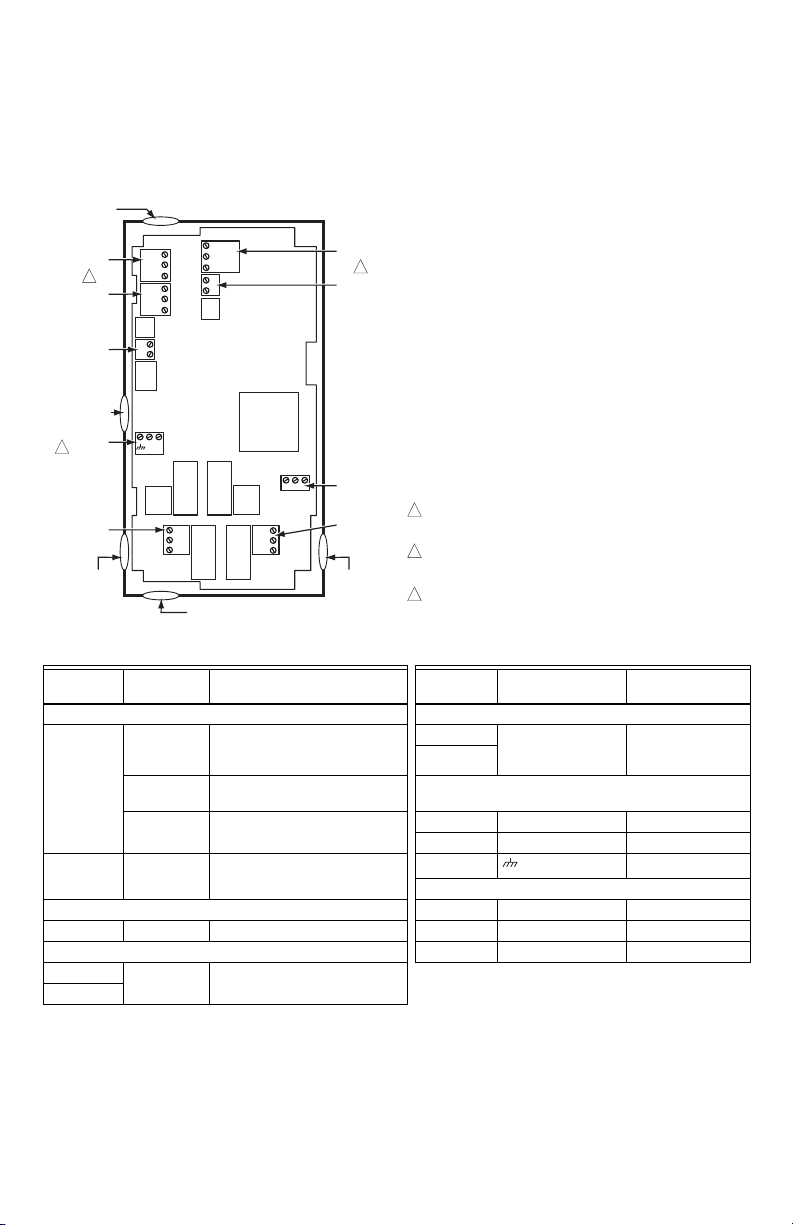
Controller Wiring Details
The wiring connection terminals are shown in Fig. 11 and
are described in Table 2. See Fig. 12 – Fig. 19 beginning
on page 9 for typical T775U wiring applications.
Fig. 11. T775U Terminal and Feature Locations.
KNOCKOUT A
–
C
MOD 1
2
MOD 2
DIGITAL
INPUT
KNOCKOUT B
POWER
3
24 VAC
OUTPUT
RELAY 1
KNOCKOUT C
NO
C
NC
KNOCKOUT E
T
S
+
T
V
T
T
NO
C
NC
B
–
R
+
W
B
–
R
+
W
–
+
C
+
120
COM
240
KNOCKOUT D
SENSOR A
1
SENSOR B
POWER
120/240 VAC
OUTPUT
RELAY 2
1
WHEN USED FOR TEMPERATURE OR 4-20mA SENSING, SENSORS A
AND B USE THE TWO TT CONNECTIONS AND ARE POLARITY
INSENSITIVE.
2
FOR MOD 1 AND MOD 2 CURRENT (mA) OR VOLTAGE (VDC) OUTPUT,
USE SIGNAL (+) & COMMON (-).
FOR MOD 1 AND MOD 2 SERIES 90 OUTPUT, USE W, R, & B.
3
A SEPARATE EARTH GROUND IS REQUIRED FOR ANY POWER
SOURCE (24, 120, OR 240 VAC)
M24553A
Table 2. Description of Wiring Terminal Connections.
Connection
Termi nal
Label Description Connection Terminal Label Description
Sensors Outputs
C – common
S – signal
V – voltage
a
Sensor A
S and V 4-20mA input; see Fig. 7 on
T T
Sensor B T T Temperature Sensor; polarity
0-10 Vdc input: Universal
sensor for humidity, pressure,
temperature, etc.
Mod 1
Mod 2
+ - (Vdc or mA)
W R B (Series 90)
page 6 24 Vac Power
Temperature Sensor; polarity
insensitive
insensitive
24V + + 24 Vac Hot
Common - 24 Vac Common
Ground
120 or 240 Vac Power
Modulating Output
b
Earth Ground
Input 120 Vac 120 120 Vac Power
DI + - Digital Input (dry contact) Common COM Common
Outputs 240 Vac 240 240 Vac Power
Relay 1 NO / COM /
Relay 2
a
For applications that do not use Reset, only Sensor A is available for use.
b
For Series 90 connections, you must insert a 340 Ohm resistor across terminals R and W. See Fig. 18 on page 10.
The resistor is included with the controller.
c
A separate earth ground is required for all installations regardless of the power source (24, 120, or 240 Vac).
62-0255—09 8
NC 120-240 Vac Relay Output
c
Page 9
T775U SERIES 2000 ELECTRONIC STAND-ALONE CONTROLLER
USE SEPARATE TRANSFORMER FOR T775 WHEN USING 24 VAC.
1
M24557B
MODULATING OUTPUT
TERMINAL (MOD 1)
B
R
W
+
–
B
R
W
+
–
POWER
1
T1 T2
–
+
HONEYWELL MODUTROL MOTOR WITH
4-20 mA MODULATING INPUT
C
NO
NC
C
NO
NC
COM
LOAD 2
LOAD 1
NO
COM
NO
COM
120V
M33844
1
FOR SPECIFIC SEN SOR WIRING (TEMPERATURE , HUMIDITY,
PRESSURE, ETC), REFER TO THE SENSOR WIRING SECTIONS
BEGINNIN G ON PAGE 4.
C
+
120
COM
240
C
S
V
T
T
–
+
1
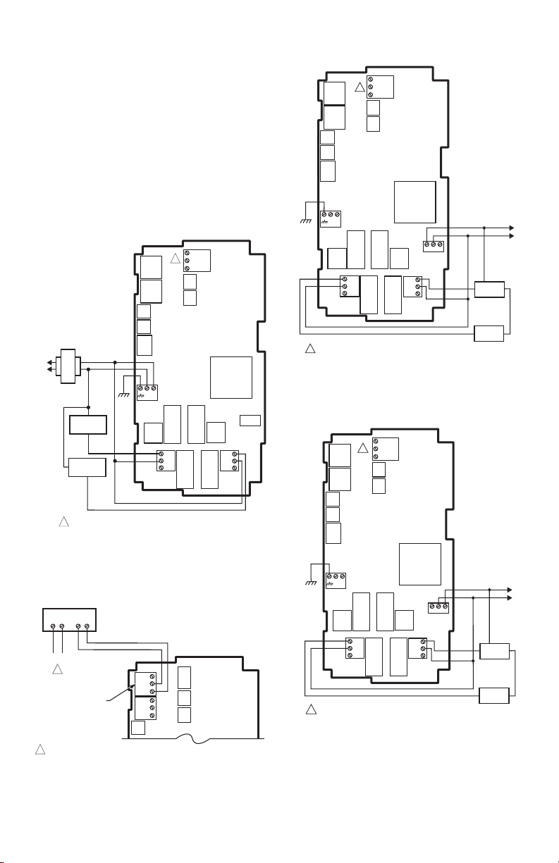
WIRING APPLICATION EXAMPLES
Fig. 12 – 19 illustrate typical controller wiring for various
applications.
NOTE: The electronic Series 90 output provided with
modulating T775 models can not drive electro-mechanical slidewire devices like older
Series 3 modulating meters (prior to Series
6), V9055s, and S984s.
NOTE: For a wiring example of three Series 90
Modutrol Motors, refer to the T775A/B/M
Series 2000 Electronic Stand-alone Controllers Installation Instructions (form 62-0254).
–
C
T
1
S
+
T
V
L1
(HOT)
L2
LOAD 1
LOAD 2
24 VAC
NO
COM
C
+
NO
C
NC
NO
C
NC
Fig. 14. Wiring for Two-stage Control with 120 Vac
(120 Vac Input and 120 Vac Load).
–
C
T
S
+
1
T
V
FOR SPECIFIC SENSOR WIRING (TEMPERATURE, HUMIDITY,
1
PRESSURE, ETC), REFER TO THE SENSOR WIRING SECTIONS
BEGINNING ON PAGE 4.
Fig. 12. Wiring for Two-stage Control – 24 Vac Input
Fig. 13. Wiring for mod motor or direct coupled
actuator with 4 to 20 mA control input.
and 24 Vac Load.
COM
NO
M24554A
C
+
NO
COM
1
NO
C
NC
FOR SPECIFIC SEN SOR WIRING (TEMPERATURE , HUMIDITY,
PRESSURE, ETC), REFER TO THE SENSOR WIRING SECTIONS
BEGINNIN G ON PAGE 4.
NO
C
NC
240V
COM
120
240
COM
NO
LOAD 2
COM
LOAD 1
M33845
Fig. 15. Wiring for Two-stage Control with 240 Vac.
9 62-0255—09
Page 10
T775U SERIES 2000 ELECTRONIC STAND-ALONE CONTROLLER
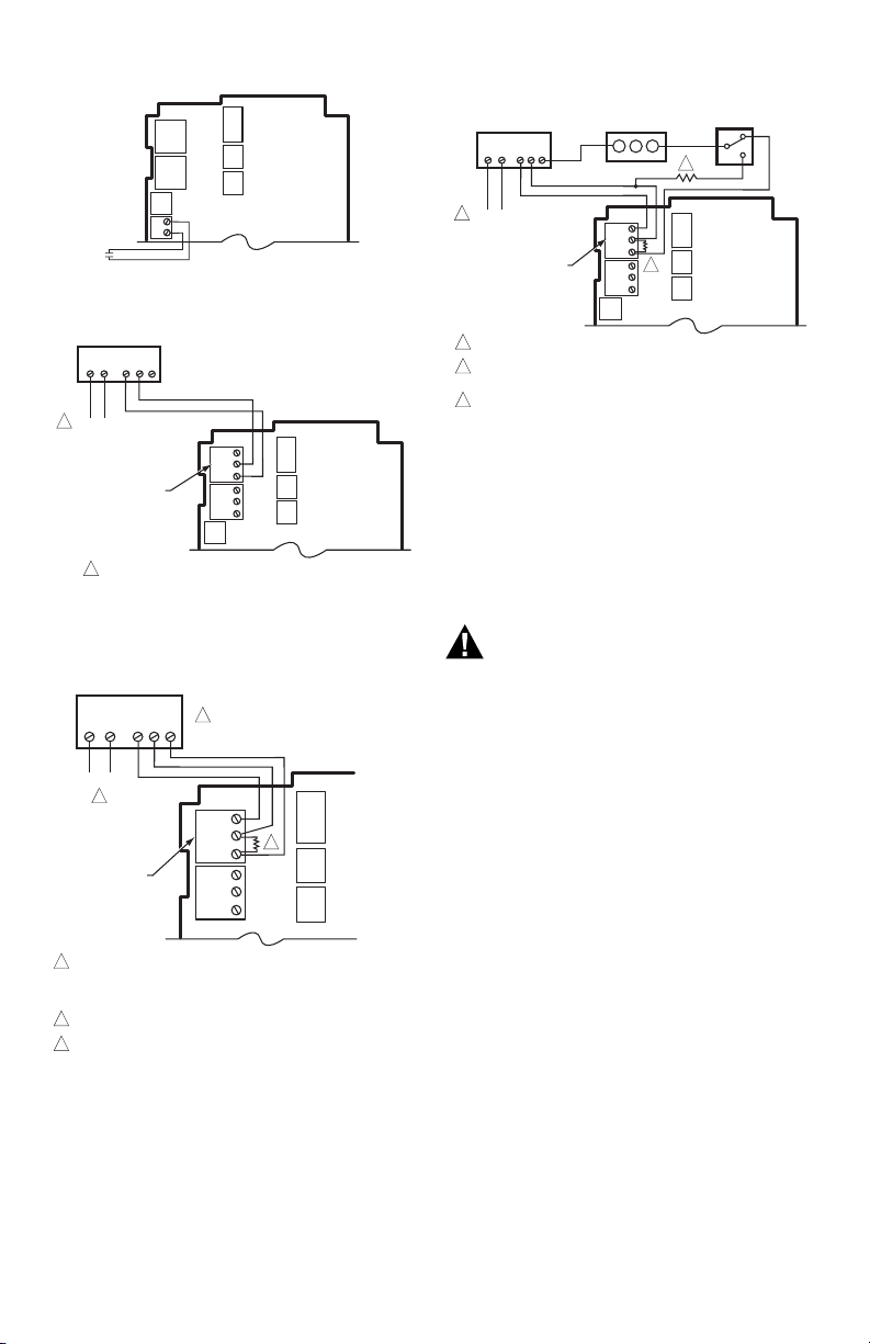
WARNING
M24560B
TO VERIFY OUTPUT, TEST OPEN CIRCUIT VOLTAGE BETWEEN
THE MOD 1 TERMINALS W AND R.
- MINIMUM (DRIVE CLOSED) SIGNAL LESS THAN 0.17 VDC
- MAXIMUM (DRIVE OPEN) SIGNAL IS GREATER THAN 1.7 VDC
USE SEPARATE TRANSFORMER FOR T775 WHEN USING 24 VAC.
INSERT 340 OHM RESISTOR (INCLUDED) ACROSS TERMINALS R AND W.
1
2
3
MODULATING
OUTPUT
TERMINAL
(MOD 1)
B
R
W
+
–
B
R
W
+
–
T1 T2 B WR
POWER
HONEYWELL ELECTRONIC
SERIES 90 MODUTROL MOTOR
1
2
3
INPUT
–
+
M24559
DIGITAL
Fig. 16. Wiring for Digital Input (dry contact).
HONEYWELL MODUTROL MOTOR WITH
VOLTAGE CONTROL INPUT
–
+
T1 T2 C R
F
1
POWER
B
–
R
+
MODULATING OUTPUT
TERMINAL (MOD 1)
1
USE SEPARATE TRANSFORMER FOR T775 WHEN USING 24 VAC.
Fig. 17. Wiring for mod motor or direct coupled
actuator with 0-10 Vdc control input.
W
B
–
R
+
W
HONEYWELL
ELECTRONIC SERIES 90
MODUTROL MOTOR
T1 T2 B WR
1
POWER
MODULATING OUTPUT
TERMINAL (MOD 1)
1
USE SEPAR ATE TRA NSFORMER FOR T775 W HEN USING 24 VAC.
A 250 OHM RES ISTOR PROVIDES 40% AUTH ORITY WHEN
2
USING A 150 OH M MINIMUM POSIT ION POTENTIOME TER.
3
INSERT 340 OHM RESISTOR (INCLUDED) ACROSS TERMINALS R AND W.
Fig. 19. Wiring for Changeover Relay and
Minimum Position Potentiometer used with
MINIMUM POSITION
POTENTIOMETER
(Q209)
W R B
B
–
R
+
W
B
3
–
R
+
W
Series 90 Modutrol Motors.
CHECKOUT
Inspect all wiring connections at the controller terminals,
and verify compliance with the installation wiring
M24558B
diagrams.
Electrical Shock Hazard.
Can cause severe injury, death or property
damage.
Disconnect power supply before beginning wiring
or making wiring connections, to prevent electrical
shock or equipment damage.
If any wiring changes are required, first be sure to remove
power from the controller before starting work. Pay
particular attention to verifying the power connection
(24, 120, or 240 Vac).
After the controller is mounted and wired, apply power.
SPDT CHANGEOVER
(H205 OR H705)
2
M24561B
Fig. 18. Wiring for Series 90 Modutrol Motor Control.
62-0255—09 10
Power Loss
The date and time settings are retained for 24 hours after
a power outage. After a power loss of more than 24 hours,
the date and time settings may need to be reentered. All
other settings are stored permanently.
Page 11
T775U SERIES 2000 ELECTRONIC STAND-ALONE CONTROLLER
M24304
TEMPERATURE (DEGREES)
RESISTANCE (OHMS)
1403
1317
1231
1145
1059
973
20 40 60 80 100 120 140 160 180 200 220
0 10 20 30 40 50 60 70 80 90 100
°F
°C
0-20-40
120
110
250
-40 -20 -10-30
1489
887
801
1097 ± 0.08 OHMS
AT 77°F (25°C)
POSITIVE TEMPERATURE COEFFICIENT (PTC) OF 2.1 OHMS PER °F
1
1
Humidity, Pressure, and Universal Sensor Calibration
A calibration parameter is available using Setup mode.
The calibration range is +/- 10% of the Min Value to Max
Value range setup for the sensor. See examples in
Tabl e 3 .
Table 3. Calibration Range Examples.
Units
Min.
Val ue
Example
Max.
Val ue
Example
Min-Max
Range
Result
PSI 100 400 300 ± 30 PSI
Inches
W.C .
Pa or
kPa
-20.0 20.0 40 ± 4 in. W.C.
-2,000 3000 5000 ± 500 Pa/kPa
% 10 100 90 ± 9%
The calibration value is set in section “1.2.2.3.
CALIBRATE (Sensor A or B)” on page 17.
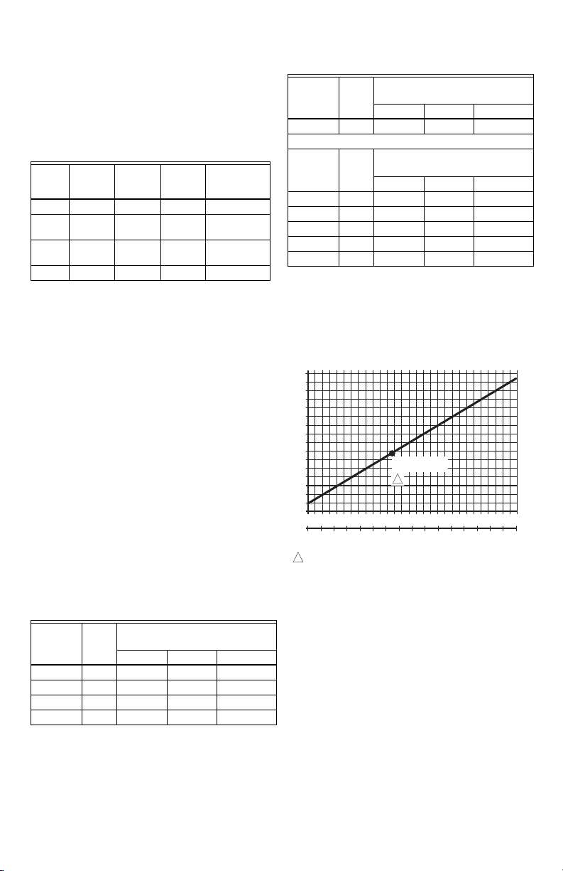
Temperature Sensor Calibration
As wire length increases, resistance increases and thus
the temperature reading increases. If necessary, calibrate
the sensor input by reducing the value by the amount
shown in the Table 4 on page 11. For example, a wire run
with 18 gauge wire of 1,000 feet, requires a calibration
offset of -6.0°F.
IMPORTANT
If the calibration value in the table exceeds the
controller’s calibration limits of +/-10°F (+/-6°C),
you must use a heavier gauge wire.
For example, with a wire run of 1,000 feet you
must use 20 AWG wire or heavier in order to calibrate for wire loss within the limits of the controller.
See “1.2.2.3. CALIBRATE (Sensor A or B)” on page 17 for
the instructions to enter the calibration value.
NOTE: The resistance output on the temperature
sensors change at the rate of 2.2 Ohms per
°F (3.85 Ohms per °C).
Table 4. Temperature Sensor Calibration for Resis-
tance Loss due to Wire Length.
Temperature Offset in
AWG
Rating m /ft
200 ft 500 ft 1,000 ft
°F (Feet)
14 2.5 0.46 1.14 2.28
16 4.0 0.72 1.82 3.64
18 6.4 1.16 2.90 5.82
20 10.2 1.86 4.64 9.28
Calibration
Range
a
Table 4. Temperature Sensor Calibration for Resis-
tance Loss due to Wire Length. (Continued)
AWG
Rating m /ft
Temperature Offset in
200 ft 500 ft 1,000 ft
°F (Feet)
a
22 16.1 2.92 7.32 14.64
AWG
Rating m /m
Temperature Offset in
°C (Meter)
100 m 200 m 300 m
a
14 8.3 0.44 0.86 1.30
16 13.2 0.68 1.38 2.06
18 21.0 1.10 2.18 3.28
20 33.5 1.74 3.48 5.22
22 52.8 2.74 5.48 8.22
a
This is the distance from the controller to the sensor
(already accounts for round trip distance).
Fig. 20 shows how sensor resistance varies with
temperature for a sensor having a positive temperature
coefficient (PTC) of 2.1 Ohms per degree F (3.85 Ohms
per degree C).
Fig. 20. Sensor Resistance vs. Temperature.
INTERFACE OVERVIEW
The T775U controller uses an LCD panel and 6-button
keypad to provide status information and permit user input
of the programming, setup, and scheduling parameters.
The following figure describes the display areas of the
LCD and the keypad.
11 62-0255—09
Page 12
T775U SERIES 2000 ELECTRONIC STAND-ALONE CONTROLLER
RELA
HOME
YS 1 2
MENU AREA
ON
SENSORS
SENSOR A
78
SENSOR B
84
o
F
o
F
DATA AREA
MOD1 40%
MOD2 60%
DI ON
home menu
LOCK ICON
6 BUTTON KEYPAD
M24563
Fig. 21. LCD Display - Home Screen And Keypad.
Menu Area – On the home screen, the LCD displays the
configured relays and whether they are active. In
Program, Setup or Schedule mode, the LCD displays the
current menu selection and its order within the menu
hierarchy.
Data Area – On the home screen, the LCD displays the
sensors and outputs status. In Setup or Program mode,
the LCD displays menu choices, parameter selections,
and data values.
Lock Icon – The icon indicates the MENU button is
locked and prevents access to the Setup and Program
menus.
NOTE: Pressing and holding the HOME and MENU
buttons simultaneously for five seconds
locks/unlocks the MENU button.
6-Button Keypad – The keypad is used to access the
menus and enter values (see “Using the LCD Panel
Interface”).
Up and Down Arrow Buttons (p and q)
Use these buttons to move your selection up and down
through a menu or list.
• When the desired item is highlighted, you press the u
arrow button to display that item’s content.
• When a value is displayed (e.g. 70°F), the up and
down arrows increase and decrease the value.
NOTE: Once you select an item from a list or enter a
value, pressing the t or u or HOME button
accepts your selection or value and stores it
in the controller’s memory.
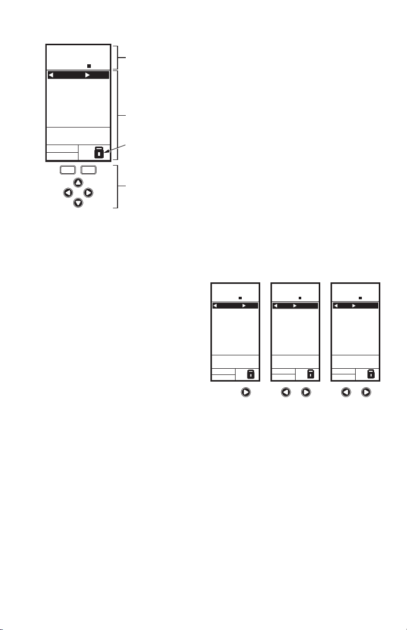
Home Screen
In the normal run state, the LCD home screen displays
the current sensed temperatures, the modulating outputs
status, the active status of the output relays, and error and
status codes.
When using Reset, the Heat/Cool setpoint(s) display on
the home screen for the Mod and Relay outputs; see
Fig. 22.
Active relays are indicated by the small black square (¢)
just below the relay number. Fig. 22 shows the home
screen with relay 2 energized.
Pressing the t and u buttons from the home screen cycles
through each modulating output that is paired with the
sensor it controls and the active output relays.
HOME
RELAYS 1 2
ON
SENSORS
SENSOR A
78
SENSOR B
84
MOD1 40%
MOD2 60%
DI ON
o
F
o
F
HOME
RELAYS 1 2
ON
MOD 1 40%
COOL
SETPOINT
74
SENSOR A
62
MOD1 40%
MOD2 60%
DI ON
o
F
o
F
HOME
RELAYS 1 2
ON
REL 2 ON
HEAT
SETPOINT
60
SENSOR A
62
RT 12345 HRS
MOD1 40%
MOD2 60%
DI ON
o
F
o
F
Using the LCD Panel Interface
The 6-button keypad is used to move through the menus
and enter or change parameter values.
Home Button
Pressing the HOME button at any time exits the current
Programming or Setup display screen and returns to the
home screen as shown in Fig. 21 and Fig. 22.
Menu Button
• Pressing the MENU button always displays the
Program menu. If you are in Setup mode, you exit
setup and return to the Program menu.
• Pressing and holding the MENU button for five
seconds leaves the current screen and displays
the Setup menu.
Left and Right Arrow Buttons (t and u)
Use these buttons to move backward (t) and forward (u)
through the Program and Setup menus.
62-0255—09 12
M24564
Fig. 22. LCD Display - Home Screen Displaying
Sensors, Mod Outputs, and Active Relays.
NOTES:
1. The modulating output home screen and the
relay home screen do not dynamically update
the active relay status, sensor values, and
modulating output percentages. The information is a snapshot taken when you press the t
or u button to display the screen.
2. In Reset mode, the home screen displays the
effective setpoint.
IMPORTANT
After four minutes of inactivity (no buttons
pressed), the LCD display reverts to the home
screen display.
Accessing the Menus
Menus are used for programming, scheduling, viewing the
summary settings, and setup of advanced options.
Page 13

T775U SERIES 2000 ELECTRONIC STAND-ALONE CONTROLLER
Program, Schedule, and Summary
Menus
To access these menus from the home screen, press the
MENU button. See Fig. 23.
HOME
RELAYS 1 2
ON
SENSORS
SENSOR A
78
SENSOR B
84
MOD1 40%
MOD2 60%
DI ON
home
menu
MENU DISPLAY WHEN
SCHEDULING IS SET
o
F
o
F
MENU
PROGRAM
SCHEDULE
SUMMARY
EXIT
SCHEDULING IS NOT SET
OR
MENU DISPLAY WHEN
MENU
PROGRAM
EXIT
M24565
Fig. 23. Menus.
Depending on whether scheduling is enabled or not, the
LCD displays one of two menus as shown in Fig. 23.
Scheduling is enabled from the Setup menu’s Output
settings (see “1.3.3.1. USE SCHED” on page 22).
Setup Menu
To access the Setup menu, press and hold the MENU
button for five seconds. See Fig. 24.
HOME
RELAYS 1 2
ON
SENSORS
SENSOR A
78
SENSOR B
84
MOD1 40%
MOD2 60%
DI ON
menu
home
o
F
o
F
SECONDS
FIVE
SENSORS
OUTPUTS
EXIT
SETUP
M24566
Fig. 24. Setup Menu.
Using the Menus
When you are working with the menus, use the:
• Left arrow button (t) to scroll backward through the
menus
• Right arrow button (u) to select the highlighted menu
item and display its content
• Up and Down arrow buttons (p and q) to scroll up and
down through a list of items or to increase or decrease
the value of a displayed parameter
NOTES:
1. If you press the HOME button or there is no
keypad activity for four minutes, you exit
Program mode and return to the home
screen.
2. If you press the MENU button, you exit and
return to the menu.
PROGRAMMING OVERVIEW
The controller must be programmed before being placed
into service.
IMPORTANT
During programming, the controller is live at all
times. For example, the contacts may open and
close when adjusting the setpoint.
The Programming process uses a hierarchical menu
structure that is easy to use. You press the t and u arrow
buttons to move forward and backward through the
menus.
NOTES:
1. The T775U controller interface is intuitive. You
may find that you do not need the following
procedure instructions to program the controller. You may want to use this procedure simply as a reference to locate the particular
option or parameter of interest.
2. The menus can display only those relays that
are defined in Setup (see “1.3.2. NBR OF
RELAYS” on page 22). For example, if you
configure only one relay, then only one relay
displays on the appropriate menus.
3. If you press the HOME button or there is no
keypad activity for four minutes, you exit Program mode and return to the home screen.
4. If you press the MENU button, you exit
Program mode and return to the menu.
Setpoint and Differential
The following describes the relationship between setpoint
and differential for heating and cooling. These settings are
programmed for each output relay.
In heating mode, reverse acting mode, and humidify
mode, the differential falls below the setpoint. The relay
de-energizes when the temperature rises to the setpoint.
As the temperature drops to the setpoint minus the
differential, the relay energizes.
In cooling mode, direct acting mode, and dehumidify
mode, the differential falls above the setpoint. The relay
de-energizes when the temperature falls to the setpoint.
As the temperature rises to the setpoint plus the
differential, the relay energizes.
Setpoint High Limit
You can set an irreversible setpoint high limit maximum
value for any single displayed setpoint value.
Adjust the setpoint (at any output) to the desired
maximum setpoint. Then, simultaneously press the
HOME, t, and u buttons and continue to press all three
buttons for five seconds to set the setpoint high limit
maximum to this value.
NOTE: You must press all three buttons at exactly
the same time for this action to occur.
13 62-0255—09
Page 14

T775U SERIES 2000 ELECTRONIC STAND-ALONE CONTROLLER
IMPORTANT
1. This action sets the maximum setpoint value of
all outputs to the setpoint high limit maximum.
2. Setting the high limit setpoint maximum is irre-
versible. If you perform the action inadvertently
and this setpoint adversely affects the control of
your system, you must replace the controller.
Programming the T775U Controller
To program the controller, perform the setup configuration
(see “1. Setup”) and then select one of the following
procedures depending on whether the Reset function is to
be used:
• Program the Outputs for No Reset — see
“2. Programming Outputs (MOD and Relay) with No
Reset” on page 26.
• Program the Outputs for Reset — see
“3. Programming Outputs (MOD and Relay) with
Reset” on page 29.
When programming is complete, you may continue with
“4. Scheduling” on page 34.
1. SETUP
Setup provides the ability to change the factory default
settings for the temperature sensors and outputs, to
enable/disable reset control, and to enable/disable
scheduling.
NOTE:
1. The T775U controller interface is intuitive. You
may find that you do not need the following
setup instructions for the sensors and outputs. You may want to use this procedure simply as a reference to locate the particular
option or parameter of interest.
2. If you press the HOME button or there is no
keypad activity for four minutes, you exit
Setup mode and return to the home screen.
3. If you press the MENU button, you exit Setup
mode and return to the menu.
Once in Setup mode, you use the —
• Left arrow button (t) to scroll backward through the
Setup menus
• Right arrow button (u) to select the highlighted menu
item and display its content
• Up and Down arrow buttons (p and q) to scroll up and
down through a list of items or to increase or decrease
the value of a displayed setup parameter
62-0255—09 14
Page 15

T775U SERIES 2000 ELECTRONIC STAND-ALONE CONTROLLER
Setup Procedure
The Setup process uses a hierarchical menu structure
that is easy to use. You press the t and u arrow buttons to
move forward and backward through the menus.
NOTE: The menus can display only those relays that
are defined in Setup (see “1.3.2. NBR OF
RELAYS” on page 22). For example, if you
configure only two relays, then only two
relays display on the appropriate menus.
SETUP
SENSORS
Fig. 25. Setup - Sensors Menu.
SETUP
SENSORS
# SENSORS
Fig. 26. Setup - Sensors - Number of Sensors.
SETUP
SENSORS
# SENSORS
SENSOR A
SENSOR B
EXIT
SETUP
SENSORS
# SENSORS
ENTER
NUMBER OF
SENSORS
M24586
2
M24587
To change the controller’s sensors and output setup
parameters, perform the following procedures in the order
listed:
1. Enter Setup mode — see “1.1. Entering Setup
Mode”
2. Setup Sensors — see “1.2. Setting up the Sensors”
3. Setup Outputs — see “1.3. Setting up the Outputs”
on page 18
4. Exit Setup Mode — see “1.4. Exiting Setup” on
page 26
1.1. Entering Setup Mode
To enter Setup mode, press and hold the MENU button for
five seconds to display the Setup menu. See Fig. 24 on
page 13.
1.2. Setting up the Sensors
1. From the Setup menu, use the p and q buttons to
highlight SENSORS.
2. Press the u button to display the Sensors menu.
1.2.1. Number of SENSORS
The value entered here determines the number of
sensors displayed on the home screen.
NOTE: For applications that do not use Reset, only
one sensor (Sensor A) is available for use.
1.
From the Sensors menu, highlight # SENSORS then
u
press the
2. Use the p and q buttons to enter the number of sen-
sors (1 or 2).
3. Press the u button to accept the value and display
the SENSOR A selection.
button to display the number of sensors.
Default: 2
SENSOR A
TYPE = PT1000
SETUP
SENSORS
SENSOR A
SETUP
SENSORS
SENSOR A
TYPE
UNITS
CALIBRATE
LABEL
EXIT
Fig. 27. Setup - Sensors - Sensor A Menu.
SENSOR A
TYPE = 0-5V, 0-10V,
OR 4-20MA
SETUP
SENSORS
SENSOR A
TYPE
UNITS
MIN VAL
MAX VAL
CALIBRATE
LABEL
EXIT
M24588A
1.2.2. SENSOR A
If you are implementing two-sensor reset control, Sensor A
must always be the controlled temperature and Sensor B must
always be the controlling temperature. For example, in a reset
control based on outside temperature, Sensor A must be the
inside sensor and Sensor B must be the outside sensor.
1. From the Sensors menu, highlight SENSOR A.
2. Press the u button to display the Sensor A selec-
tions.
The menu selections change depending on whether the
sensor type is 1097 PTC (temperature) or 0-10V / 4-
20MA.
15 62-0255—09
Page 16

T775U SERIES 2000 ELECTRONIC STAND-ALONE CONTROLLER
A
SETUP
SENSORS
SENSOR A
TYPE
SENSORS
SENSOR A
PT 1000
0-5V
0-10V
4-20MA
TYPE FOR
SENSOR A
SETUP
TYPE
SELECT
Fig. 28. Setup - Sensors - Sensor A - Type.
SETUP
SENSORS
SENSOR A
UNITS
SENSORS
SENSOR A
DEG F
DEG C
UNITS FOR
SENSOR A
SETUP
UNITS
SELECT
Fig. 29. Setup - Sensors - Sensor A - Units.
1.2.2.1. TYPE (Sensor A only)
1. From the Sensor A selections, use the p and q but-
tons to highlight TYPE.
2. Press the u button to display the type values.
3. Use the p and q buttons to highlight the desired
value PT1000 (1097 PTC), 0-5V, 0-10V, or 420MA.
Default: PT1000
NOTE: The default label PT1000 refers to a 1097
PTC temperature sensor.
M24589
4. Press the u button to accept the units and return to
the Sensor A selections.
5. For PT1000 (1097 PTC) temperature sensors, go
to “1.2.2.2.1. UNITS (Sensor A or B; PT1000
[1097W PTC)]”.
For 0-5V, 0-10V, and 4-20MA sensors, go to
“1.2.2.2.2. UNITS (Sensor A only; 0-5V, 0-10V, or 420mA)”
1.2.2.2.1. UNITS (Sensor A or B; PT1000
[1097 PTC)]
If Sensor A is configured for °F or °C units, then the units
selection does not appear for Sensor B, since Sensor B
uses the units specified for Sensor A.
1. From the Sensor A selections, use the p and q but-
tons to highlight UNITS.
2. Press the u button to display the temperature units.
3. Use the p and q buttons to highlight F or C.
Default: F (Fahrenheit)
M24590
4. Press the u button to accept the units and return to
the Sensor A selections.
Continue with “1.2.2.3. CALIBRATE (Sensor A or B)”.
SETUP
SENSORS
SENSOR A
UNITS
SENSORS
SENSOR A
DEG F
DEG C
PSI
IN WC
% RH
PA
KPA
PPM
NONE
UNITS FOR
SENSOR A
SETUP
UNITS
SELECT
M24591A
Fig. 30. Setup - Sensors - Sensor A - Units.
62-0255—09 16
1.2.2.2.2. UNITS (Sensor A only; 0-5V, 0-10V, or
4-20mA)
1. From the Sensor A selections, use the p and q but-
tons to highlight UNITS.
2. Press the u button to display the units list.
3. Use the p and q buttons to scroll through the list and
highlight the desired unit of measure.
You may need to scroll up or down to view all units.
Default: F (Fahrenheit)
4. Press the u button to accept the units and return to
the Sensor A selections.
Page 17

T775U SERIES 2000 ELECTRONIC STAND-ALONE CONTROLLER
ENTER
MINIMUM
VALUE FOR
SENSOR A
SETUP
SENSORS
SENSOR A
MIN VAL
0.0
F
o
M24592A
ENTER
MAXIMUM
VALUE FOR
SENSOR A
SETUP
SENSORS
SENSOR A
MAX VAL
0.0
F
o
SETUP
SENSORS
SENSOR A
MIN VAL
OR
MAX VAL
Fig. 31. Setup - Sensors - Sensor A - 0-5V, 0-10V, OR 4-
20MA - MIN and MAX Value (showing °F).
SETUP
SENSORS
SENSOR A
CALIBRATE
SETUP
SENSORS
SENSOR A
CALIBRATE
0.0
ENTER
VALUE TO
CALIBRATE
SENSOR A
o
F
M24594
Fig. 32. Setup - Sensors - Sensor A - Calibrate.
1.2.2.2.3. MIN or MAX VALUE
(Sensor A only;
0-5V, 0-10V or 4-20mA)
The minimum and maximum values display only for
Sensor A when its type is
1. From the Sensor A selections, use the p and q but-
tons to highlight MIN VAL or MAX VAL.
2. Press the u button to display the units.
3. Use the p and q buttons to increase/decrease the
desired value.
Sensor Ranges:
PPM 0 to 9990
NONE -9999 to 9999
4. Press the u button to accept the units and return to
the Sensor A selections.
0-5V,
0-10V or 4-20MA.
°F-60.0 to 270.0
°C-51.0 to 132.0
PSI-500 to 500
IN WC-30.0 to 30.0
%0.0 to 100.0
PA-3000 to 3000
KPA-3000 to 3000
1.2.2.3. CALIBRATE (Sensor A or B)
Ensure that the wire size calibration value is within the
limits for the sensor.
• For temperature sensors, see “Temperature Sensor
Calibration” on page 11.
• For other sensors, see “Humidity, Pressure, and
Universal Sensor Calibration” on page 11.
1. From the Sensor A selections, use the p and q but-
tons to highlight CALIBRATE.
2. Press the u button to display the calibration value.
3. Use the p and q buttons to increase/decrease the
desired calibration value.
Default: 0.0
Sensor Range Temperature: +/-10°F (+/-6°C)
Other Sensor Range: +/-10% of the Min to Max
values specified previously. See Table 3 on
page 11 for examples.
4. Press the u button to accept the value and return to
the Sensor A selections.
SETUP
SENSORS
SENSOR A
LABEL
Fig. 33. Setup - Sensors - Sensor A - Label.
SETUP
SENSORS
SENSOR A
LABEL
SENSOR A
BOILER A
OUTDOOR A
DUCT A
DISCHRG A
CHILLER A
ROOM A
SELECT
LABEL FOR
SENSOR A
1.2.2.4. LABEL (Sensor A or B input)
For a sensor already labeled, the display positions to and
highlights that label.
1. From the Sensor A selections, use the p and q but-
tons to highlight LABEL.
2. Press the u button to display the label list.
3. Use the p and q buttons to scroll through the list and
highlight the desired label.
You may need to scroll up or down to view all possible labels.
M24595
4. Use the u button to accept the highlighted label and
exit the list.
NOTE: The label names in list order are: Sensor,
Boiler, Outdoor, Duct, Dischrg, Chiller, Room,
Supply, Return, and Animals.
17 62-0255—09
Page 18

T775U SERIES 2000 ELECTRONIC STAND-ALONE CONTROLLER
A
SETUP
SENSORS
SENSOR A
UNITS
CALIBRATE
LABEL
EXIT
Fig. 34. Setup - Sensors - Sensor A - Exit.
SETUP
SENSORS
SETUP
SENSORS
# SENSORS
SENSOR A
SENSOR B
EXIT
Fig. 35. Setup - Sensors - Sensor B Menu.
1.2.2.5. Exit Sensor A Setup
Press the t button to exit Sensor A selections and return
to the Sensors menu.
or
Use the p and q buttons to highlight EXIT and press the u
button.
Continue with “1.2.3. SENSOR B (Temperature only)”
M24596
1.2.3. SENSOR B (Temperature only)
For two-sensor reset control, Sensor B must always be
the controlling temperature. For example, in a reset
control based on outside temperature, Sensor B must be
the outside sensor.
NOTE: Sensor B is available only for reset on the
T775U2006, but can be controlled just like
Sensor A on the T775U2016.
1. From the Sensors menu, use the q button to high-
M24597
light SENSOR B.
2. Press the u button to display the Sensor B menu.
3. Repeat the selections described in “1.2.2. SENSOR
A” through “1.2.2.4. LABEL (Sensor A or B input)”
beginning on page 15, but perform only those steps
applicable to Sensor B.
4. Press the t button to exit SENSOR B and return to
the Sensors menu.
or
Use the p and q buttons to highlight EXIT and press
the u button.
5. Press the t button to exit the Sensors menu and
return to the Setup menu.
SETUP
OUTPUTS
MOD 1
SETUP
OUTPUTS
MOD 1
TYPE
MIN OUT %
INTEGRAL
DERIVATIV
SCHEDULE
RESET
HIDE
EXIT
Fig. 36. Setup - Outputs Menu.
62-0255—09 18
M24599
Continue with “1.3. Setting up the Outputs”.
1.3. Setting up the Outputs
1. From the Setup menu, use the pand q buttons to
highlight OUTPUTS.
2. Press the u button to display the Outputs menu.
NOTE: The menus (e.g. the Outputs menu shown
here) can display only those relays that are
defined in Setup (see page 22). For example,
if you configure only two relays, then only
two relays display on the appropriate menus.
The following procedures set up each modulating output
and relay output.
Page 19

T775U SERIES 2000 ELECTRONIC STAND-ALONE CONTROLLER
SETUP
OUTPUTS
MOD 1
SETUP
OUTPUTS
MOD 1
TYPE
MIN OUT %
INTEGRAL
DERIVATIV
SCHEDULE
RESET
EXIT
M24599
Fig. 37. Setup - Outputs - Modulating Output Menu.
SETUP
OUTPUTS
MOD 1
TYPE
SETUP
OUTPUTS
MOD 1
TYPE
4 - 20 mA
0-10 V
2-10 V
SERIES 90
SELECT
TYPE FOR
MOD 1
M24600
Fig. 38. Setup - Outputs - Mod Out - Type.
SETUP
OUTPUTS
MOD 1
MIN OUT %
Fig. 39. Setup - Outputs - Mod Out - Minimum Output
Perce ntage.
SETUP
OUTPUTS
MOD 1
MIN OUT %
0
ENTER
MINIMUM
PERCENT FOR
MOD 1
%
M24601
1.3.1. Setting up the Modulating Outputs
1. From the Output menu, use the p and q buttons to
highlight the desired modulating output (MOD 1 or
MOD 2).
2. Press the u button to display the selected MOD
menu.
Use the remaining procedures, beginning with “1.3.1.1.
TYPE (of output signal)”, to set up each modulating
output. If you have two modulating outputs, repeat these
procedures for each modulating output.
1.3.1.1. TYPE (of output signal)
1. From the Mod menu, use the p and q buttons to
highlight TYPE.
2. Press the u button to display the Type selections.
3. Use the pand q buttons to highlight the desired out-
put type.
Default: 4-20 mA
4. Press the u button to accept the selected type and
return to the Mod menu.
1.3.1.2. MIN OUT %
The minimum output % prevents the output from dropping
below the value entered. This value can be useful to
maintain minimum damper position.
Using the time clock or digital input to disable the output
forces the output to 0%.
1. From the Mod menu, use the p and q buttons to
highlight MIN OUT %.
2. Press the u button to display the Min Out %.
3. Use the p and q buttons to increase/decrease the
desired value from 0% to 100% in 1% increments.
Default: 0%
Range: 0 to 100%
4. Press the u button to accept the percentage and
return to the Mod menu.
SETUP
OUTPUTS
MOD 1
INTEGRAL
Fig. 40. Setup - Outputs - Mod Out - Integral.
SETUP
OUTPUTS
MOD 1
INTEGRAL
400
ENTER
INTEGRAL
TIME FOR
MOD 1
SEC
1.3.1.3. INTEGRAL
1. From the Mod menu, use the p and q buttons to
highlight INTEGRAL.
2. Press the u button to display the Integral seconds.
3. Use the p and q buttons to increase/decrease the
value from 0 to 3,600 in 10 second increments.
Default: 400 seconds
Range: 0 to 3,600 seconds
4. Press the u button to accept the seconds and return
to the Mod menu.
M24602
See the Notes on page 20 for Integral timing information.
19 62-0255—09
Page 20

T775U SERIES 2000 ELECTRONIC STAND-ALONE CONTROLLER
NOTES: (Integral Timing)
1. The Integral time is factory set for 400 seconds. This
is a good middle range and should satisfy many
applications. The integral time can be increased for
applications where sensed response is slow, and can
be decreased for applications where sensed
response is fast (e.g. discharge air control).
2. As a starting point, an optimal integral time for
discharge air typically ranges from 12 to 200
seconds. An optimal integral time for room control
typically ranges from 60 to 2,500 seconds. The
purpose of integral action is to reduce or eliminate
the offset from setpoint during steady state control
that is often seen in proportional only control.
3. Keep in mind that control is most sensitive to
throttling range. Adjust the throttling range first before
any adjustment to integral time. Adjust throttling
range to be as wide as possible to start since this will
provide the most stable control. Remember that the
integral will eliminate the steady state error so you do
not need to have a small throttling range to have
accurate control. (Integral action allows for controlling
to a setpoint even with a wide throttling range).
SETUP
OUTPUTS
MOD 1
DERIVATIV
SETUP
OUTPUTS
MOD 1
DERIVATIV
0
ENTER
DERIVATIVE
TIME FOR
MOD 1
SEC
Fig. 41. Setup - Outputs - Mod Out - Derivative.
SETUP
OUTPUTS
MOD 1
SCHEDULE
OUTPUTS
SCHEDULE
YES
NO
SCHEDULE
OUTPUTS
SETUP
MOD 1
USE
FOR
Fig. 42. Setup - Outputs - Mod Out - Schedule.
1.3.1.4. DERIVATIVE
The Derivative default value is factory set to zero (no
derivative control). It is strongly recommended that the
derivative remain at zero (0) unless you have a very good
reason to adjust it. Derivative control is not needed in the
vast majority of HVAC applications.
1. From the Mod menu, use the p and q buttons to
highlight DERIVATIV.
2. Press the u button to display the Derivative sec-
onds.
M24603
3. Use the p and q buttons to increase/decrease the
value.
Default: 0 (zero)
Range: 0 to 3,600 seconds
4. Press the u button to accept the seconds and return
to the Mod menu.
1.3.1.5. SCHEDULE
The Schedule option displays only if the USE SCHED
parameter is set to Yes (see page 22).
1. From the Mod menu, use the p and q buttons to
highlight SCHEDULE.
2. Use the p and q buttons to highlight YES or NO.
Default: YES
3. Press the u button to accept the selection and
return to the Mod menu.
Each output can be set up to follow or ignore the built in
M24604
scheduler. To disable the scheduler for all outputs, see
“1.3.3.1. USE SCHED” on page 22.
62-0255—09 20
Page 21

T775U SERIES 2000 ELECTRONIC STAND-ALONE CONTROLLER
SETUP
OUTPUTS
MOD 1
RESET
SETUP
OUTPUTS
MOD 1
RESET
YES-BOILER
YES-OTHER
NO
USE
RESET
FOR
MOD1
Fig. 43. Setup - Outputs - Mod Out - Reset.
SETUP
OUTPUTS
MOD 1
HIDE
SETUP
OUTPUTS
MOD 1
HIDE
YES
NO
HIDE MOD 1 ON
HOME SCREEN
Fig. 44. Setup - Outputs - Mod 1/2- Hide.
1.3.1.6. RESET
This selection enables the controller’s Reset function, and
allows each output to be individually programmed for
Reset or No Reset.
IMPORTANT
To use the Reset function of the controller, the
first modulating output (MOD1) must be set for
Reset here.
The RESET choice is offered for all outputs in setup
mode, and you can set any or all of them for Reset=YES
M24605
or Reset=NO. The default is Reset=NO.
For the remaining outputs, if Reset=YES, then these
outputs use the reset curve programmed for the first
output.
1. From the Mod menu, use the p and q buttons to
highlight RESET.
2. Use the p and q buttons to highlight the desired
value.
Default: NO
3. Press the u button to accept the selection and
return to the Mod menu.
1.3.1.7. Hide
The Hide option is used to prevent the MOD 1 and MOD 2
outputs from displaying on the Home screen.
1. From the Mod menu, use the p and q buttons to
highlight HIDE.
2. Use the p and q buttons to highlight YES or NO.
Default: YES
3. Press the u button to accept the selection and
return to the MOD menu.
NOTE: The MOD1 and MOD2 outputs are still active
M28656
even when hidden from the Home screen.
SETUP
OUTPUTS
MOD 1
TYPE
MIN OUT %
INTEGRAL
DERIVATIV
SCHEDULE
EXIT
Fig. 45. Setup - Outputs - Mod Out - Exit.
1.3.1.7. Exit Modulating Outputs Setup
Press the t button (or highlight EXIT and press the u
button) to exit the Mod menu and return to the Outputs
menu.
To configure the second modulating output, go to “1.3.1.
Setting up the Modulating Outputs” on page 19.
When you finish setting up the two modulating outputs,
continue with “1.3.2. NBR OF RELAYS”.
M24606
21 62-0255—09
Page 22

T775U SERIES 2000 ELECTRONIC STAND-ALONE CONTROLLER
A
SETUP
OUTPUTS
OPTIONS
USE SCHED
SETUP
OUTPUTS
OPTIONS
USE SCHED
USE
SCHEDULE
FOR
OUTPUTS
YES
NO
M24609
SETUP
OUTPUTS
# RELAYS
SETUP
OUTPUTS
# RELAYS
2
ENTER
NUMBER OF
RELAYS
Fig. 46. Setup - Outputs - Number of Relays.
SETUP
OUTPUTS
OPTIONS
Fig. 47. Setup - Outputs - Options Menu.
Fig. 48. Setup - Outputs - Options - Schedule.
SETUP
OUTPUTS
OPTIONS
USE SCHED
MIN OFF
MIN ON
DI OPTS
SHOW RT
EXIT
M24607
M24608
1.3.2. NBR OF RELAYS
1. From the Outputs menu, use the pand q buttons to
highlight # RELAYS.
2. Press the u button to display the number of relays.
3. Use the p and q buttons to display the number from
1 to 2.
4. Press the u button to accept the value and display
the Outputs menu.
The number of relay outputs entered here determines
how many relays display on the home screen.
1.3.3. OPTIONS
1. From the Outputs menu, use the pand q buttons to
highlight OPTIONS.
2. Press the u button to display the Options menu.
1.3.3.1. USE SCHED
1.
Press the u button to display the schedule selections.
2. Use the pand q buttons to highlight YES or NO.
Default: NO
3. Press the u button to accept the value and display
the MIN OFF option.
Selecting NO disables scheduling for all outputs.
Selecting YES enables scheduling for all outputs. When
YES is selected, all individual outputs default to follow the
schedule. However, each individual output can be
removed from scheduling as desired.
With Scheduling enabled, when you return to Program
mode, the new option for Scheduling displays. You can
press the HOME button and then the MENU button to
view the Schedule options in the menu.
See “1.3.1.5. SCHEDULE” on page 20.
62-0255—09 22
Page 23

T775U SERIES 2000 ELECTRONIC STAND-ALONE CONTROLLER
M24610A
SETUP
OUTPUTS
OPTIONS
ENTER
MINIMUM
OFF TIME
FOR RELAYS
SETUP
OUTPUTS
OPTIONS
MIN OFF
0
SEC
OR
MIN ON
SETUP
OUTPUTS
OPTIONS
MIN ON
0
SEC
MIN OFF
ENTER
MINIMUM
ON TIME
FOR RELAYS
Fig. 49. Setup - Outputs - Options - Min Off/On Time.
1.3.3.2. MIN OFF or MIN ON
This is the minimum number of seconds of “off time” or
“on time” for all relays.
1. Press the u button to display the Min Off/On value.
2. Use the p and q buttons to increase/decrease the
desired number of seconds from 0 to 990 seconds
in 10 second increments.
Default: 0 (zero)
Range: 0 to 990 seconds
3. Press the u button to accept the seconds and
display the DI OPTIONS.
NOTES:
1. The minimum off time applies to all relay
outputs.
2. When minimum off time is active, relays
waiting to be energized display a flashing
square underneath the relay number on the
home screen.
3. If the minimum off time is not equal to zero
(0), the minimum off time activates at powerup. To manually override, press the t button at
any time.
23 62-0255—09
Page 24

T775U SERIES 2000 ELECTRONIC STAND-ALONE CONTROLLER
SETUP
OUTPUTS
OPTIONS
DI OPTS
SETUP
OUTPUTS
OPTIONS
DI OPTS
DISABLE
SETPOINT
SETBACK
ENABLE
IGNORE
SELECT DI
OPTIONS
FOR
OUTPUTS
M24611A
Fig. 50. Setup - Outputs - Options - DI Options.
SETUP
OUTPUTS
OPTIONS
SHOW RT
YES
NO
SETUP
OUTPUTS
OPTIONS
SHOW RT
USE
RUNTIME
FOR
RELAYS
M24612
Fig. 51. Setup - Outputs - Options - Show Runtime.
1.3.3.3. DI OPTIONS (digital input options)
The DI Option you select applies to all outputs. This
option overrides any Setpoint/Setback values entered in
the Schedule.
1. Press the u button to display the DI Option selec-
tions.
2. Use the p and q buttons to highlight DISABLE, SET-
BACK, or IGNORE.
Default: DISABLE
3. Press the u button to accept the value and display
the SHOW RT option.
When the digital input (DI) closes, all outputs follow the DI
option value (Disable, Setback, or Ignore):
• DISABLE disables the outputs; relays return to deenergized state and Mod outputs return to 0% output.
• SETPOINT forces the control to the setpoint
temperature.
• SETBACK enables a setback temperature value to be
programmed for each output.
— To program the Setback temperature with Reset,
see Fig. 74 on page 32.
— To program the Setback temperature without
Reset, see Fig. 61 on page 27.
• ENABLE energizes all relays to 100%. Use this option
carefully.
• IGNORE causes the digital input to have no effect on
the Relay or Mod outputs.
1.3.3.4. SHOW RT (show run time hours)
1. Press the u button to display the Show RT values.
2. Use the p and q buttons to select YES or NO.
Default: YES
3. Press the u button to accept the value and return to
the Options menu.
Selecting YES shows the RT (run time) hours for each
relay on the home screen displays.
NOTE: Run times can be reset to zero for each indi-
vidual relay. You must do this for each relay
that you want to reset to zero. See “1.3.4.3.
RESET RT (run time)” on page 26.
SETUP
OUTPUTS
OPTIONS
USE SCHED
MIN OFF
DI OPTION
SHOW RT
EXIT
M24613
Fig. 52. Setup - Outputs - Options - Exit.
62-0255—09 24
1.3.3.5. Exit Options Setup
Press the t button to exit the Options set up and return to
the Outputs menu.
or
Use the p and q buttons to highlight EXIT and press the u
button.
Continue with “1.3.4. Setting up the Relays”.
Page 25

T775U SERIES 2000 ELECTRONIC STAND-ALONE CONTROLLER
SETUP
OUTPUTS
RELAY 1
RESET
USE
RESET
FOR
RELAY 1
YES
NO
SETUP
OUTPUTS
RELAY 1
RESET
M24616
SETUP
OUTPUTS
RELAY 1
SETUP
OUTPUTS
RELAY 1
SCHEDULE
RESET
RESET RT
EXIT
Fig. 53. Setup - Outputs - Relay Menu.
SETUP
OUTPUTS
RELAY 1
SCHEDULE
OUTPUTS
SCHEDULE
YES
NO
SCHEDULE
OUTPUTS
SETUP
RELAY 1
USE
FOR
Fig. 54. Setup - Outputs - Relay - Schedule.
Fig. 55. Setup - Outputs - Relay - Reset.
1.3.4. Setting up the Relays
1. From the Outputs menu, use the p and q buttons to
highlight the desired relay (1 or 2).
2. Press the u button to display the selected Relay
menu.
Continue with the remainder of this section to setup the
relay outputs.
M24614
1.3.4.1. SCHEDULE
This selection displays only if “Use Sched = YES” is
selected during the Output Options setup (see page 22).
When selected, individual outputs default to follow the
schedule.
1. Press the u button to display the Schedule values.
2. Use the p and q buttons to select YES or NO.
Default: YES
3. Press the u button to accept the value and return to
the Relay menu.
An individual output can be selected to be controlled or
M24615
not controlled by the schedule.
If NO is selected, the Setback selection does not appear
in the Program menu for this output.
1.3.4.2. RESET
IMPORTANT
For relays to use the Reset function of the controller, both modulating outputs (MOD 1 and
MOD 2) must be set for Reset.
Relays that have Reset set to YES use the reset curve
configured for MOD 1.
1. Press the u button to display the Reset values.
2. Use the p and q buttons to select YES or NO.
Default: NO
3. Press the u button to accept the value and return to
the Relay menu.
• If you select YES, then all other outputs display this
Setup option and will use the reset curve programmed
for th e first output .
• If you select NO, then No Reset is configured for that
output and all other subsequent outputs.
25 62-0255—09
Page 26

T775U SERIES 2000 ELECTRONIC STAND-ALONE CONTROLLER
SETUP
OUTPUTS
RELAY 1
RESET RT
YES
NO
SETUP
OUTPUTS
RELAY 1
RESET RT
RESET
RUN TIME
FOR
RELAY 1
M24617
Fig. 56. Setup - Outputs - Relay - Reset Runtime.
SETUP
OUTPUTS
RELAY 1
RESET
SCHEDULE
RESET RT
EXIT
M24618
Fig. 57. Setup - Outputs - Relay - Exit.
1.3.4.3. RESET RT (run time)
This selection displays only if “Show RT = YES” is
selected during Output Options setup (see page 24).
1. Press the u button to display the Reset RT values.
2. Use the p and q buttons to select YES or NO.
Default: NO
3. Press the u button to accept the value and return to
the Relay menu.
Selecting YES immediately resets the output run time
hours to zero for this output. When you subsequently
return to this screen, the RESET RT defaults to NO.
NOTE: Run times can be reset to zero for each indi-
vidual relay. You must do this for each relay
that you want to reset to zero.
1.3.4.4. EXIT Relay Setup
Press the t button to exit the selected relay set up and
return to the Outputs menu.
To setup the next relay output go to “1.3.4. Setting up the
Relays” on page 25.
When you finish setting up the relay outputs, continue with
“1.4. Exiting Setup”.
1.4. Exiting Setup
Press the HOME button to exit Setup mode and return to
the home screen display.
or
Use the p and q buttons to highlight EXIT from the menu
and press the u button.
This completes the Setup procedure.
2. PROGRAMMING OUTPUTS
(MOD AND RELAY) WITH NO
RESET
The T775U can be programmed for Reset or No Reset.
From the factory, the T775U is programmed for No Reset.
This section describes the steps necessary to program
the controller for No Reset.
62-0255—09 26
NOTE: For applications where Reset is not used,
only one sensor (Sensor A) is available for
use.
Page 27

T775U SERIES 2000 ELECTRONIC STAND-ALONE CONTROLLER
MENU
PROGRAM
MENU
PROGRAM
MOD 1
MOD 2
RELAY 1
RELAY 2
EXIT
M24567
PROGRAM
MOD 1
MENU
PROGRAM
MOD 1
SETPOINT
SETBACK
SENSOR
THROT RNG
ACTION
EXIT
M24580A
2.1. Entering Program Mode
Press the MENU button, then select PROGRAM and
press the u button to view the Program menu.
Fig. 58. Program Menu.
2.1.1. Program Menu for Outputs with
No Reset
From the Program menu, select MOD 1, MOD 2,
RELAY 1, or RELAY 2 to view the parameters. This
section illustrates the screens for selecting MOD 1, but
other than as noted below, the programming is the same
for each output.
NOTE: For Relays, DIFFRNTL replaces THROT RNG.
NOTE: The Setback parameter displays only if
scheduling is enabled (see Fig. 48 on
Fig. 59. Program Menu - No Reset.
page 22) or the DI Option is set to Setback.
(see Fig. 50 on page 24).
Continue with “2.1.2. SETPOINT”.
PROGRAM
MOD 1
SETPOINT
Fig. 60. Program - Setpoint.
PROGRAM
MOD 1
SETBACK
Fig. 61. Program - Setback.
MENU
PROGRAM
MOD 1
SETPOINT
70
ENTER
SETPOINT
FOR
MOD 1
MENU
PROGRAM
MOD 1
SETBACK
60
ENTER
SETBACK
SETPOINT
FOR MOD 1
2.1.2. SETPOINT
1. From the menu, use the p and q buttons to highlight
SETPOINT.
2. Press the u button to display the setpoint value.
3. Use the p and q buttons to increase/decrease the
o
F
M24581
desired setpoint temperature.
Default: 70°F (21°C)
Range: -40°F to 248°F (-40°C to 120°C)
4. Press the u button to accept the setpoint tempera-
ture and display the next option.
2.1.3. SETBACK
The Setback temperature option displays only if
scheduling is enabled (see Fig. 48 on page 22) or the DI
Option is set to Setback. (see Fig. 50 on page 24).
This is the desired setpoint temperature that you want to
o
F
use during setback mode for this output. For example, if
your setpoint is 70°F and you want the temperature to
drop 10°F during setback mode, enter 60°F as the setpoint for this output.
M24584
1. From the menu, use the p and q buttons to highlight
SETBACK.
2. Use the p and q buttons to increase/decrease the
desired setpoint temperature.
27 62-0255—09
Page 28

T775U SERIES 2000 ELECTRONIC STAND-ALONE CONTROLLER
Default: 60°F (16°C)
Range: -40°F to 248°F (-40°C to 120°C)
3. Press the u button to accept the value and display
the menu.
PROGRAM
MOD 1
SENSOR
MENU
PROGRAM
MOD 1
SENSOR
SENSOR A
SENSOR B
SELECT
SENSOR
FOR
MOD 1
M28660
Fig. 62. Program - Sensor.
PROGRAM
MOD1
THROT RNG
MENU
PROGRAM
MOD 1
THROT RNG
20
ENTER
THROTLLING
RANGE FOR
MOD 1
o
F
M24582
Fig. 63. Program - Throttling Range or Differential.
2.1.3. SENSOR
This sub-menu choice is only available on the T775U2016
model.
1. From the menu, use the p and q buttons to highlight
SENSOR A or SENSOR B.
2. Press the u button to accept the sensor selection
and display the next option.
2.1.5. THROTTLING RANGE or
DIFFERENTIAL
Throttling Range displays for Modulating outputs.
Differential is used for the Relay outputs.
1. From the menu, use the p and q buttons to highlight
THROT RNG or DIFFERNTL.
2. Press the u button to display the throttling range
value.
3. Use the p and q buttons to increase/decrease the
desired value.
Default: 20°F (-6.6°C)
Range: 1°F to 150°F (1°C to 66°C)
4. Press the u button to accept the value and display
the next option.
The Throttling Range brackets the setpoint setting, e.g., if
the setpoint is 72°F and the throttling range is 10°F, then
the effective throttling temperature range is 67°F to 77°F.
In heating mode, the Differential is below the setpoint. The
relay de-energizes when the temperature rises to the
setpoint. As the temperature drops to the setpoint minus
the Differential, the relay energizes.
In cooling mode, the Differential is above the setpoint. The
relay de-energizes when the temperature falls to the
setpoint. As the temperature rises to the setpoint plus the
Differential, the relay energizes.
PROGRAM
MOD 1
ACTION
MENU
PROGRAM
MOD 1
ACTION
HEAT
COOL
REV ACT
DIR ACT
HUMID
DEHUMID
SELECT
ACTION
MOD 1
FOR
M24583
Fig. 64. Program - Action.
62-0255—09 28
2.1.6. ACTION
1. From the menu, use the p and q buttons to highlight
ACTION.
Default: HEAT
2. Press the u button to display the action selections.
3. Use the p and q buttons to select the desired value.
4. Press the u button to accept the highlighted selec-
tion and display the next option.
Page 29

T775U SERIES 2000 ELECTRONIC STAND-ALONE CONTROLLER
SETUP
OUTPUTS
MOD 1
RESET
SETUP
OUTPUTS
MOD 1
RESET
USE RESET
FOR
MOD 1
YES-BOILER
YES-OTHER
NO
M24568
2.2. Program Next Output (Modulating
Output or Relay)
For the next output, select the desired MOD or Relay from
the Program menu (see Fig. 58 on page 27).
Go to “2.1.2. SETPOINT” on page 27 to continue
programming.
When you finish programming the outputs, continue with
“1.3. Exit Programming without Reset”.
1.3. Exit Programming without Reset
Press the HOME button to leave programming mode and
return to the home screen.
This completes the programming procedure for controllers
that do not use Reset.
3. PROGRAMMING OUTPUTS
(MOD AND RELAY) WITH
RESET
The T775U can be programmed for Reset or No Reset for
each output. From the factory, the T775U is programmed
for No Reset. This section describes the steps necessar y
to program the controller for Reset.
To use the Reset feature, the first output (MOD 1) must be
set to Reset=YES in Setup mode (see “3.1. Setting Up the
Controller for Reset”).
Fig. 65. Reset Setup.
Determining and Setting the Reset Val ues
NOTE: When using the Reset feature, Sensor A must
be sensing the controlled temperature (e.g.
Boiler), Sensor B must be sensing the resetting temperature (e.g. outdoor temp).
To program an output for Reset, refer to the values as
shown in the examples below. Choose your own
appropriate values for Sensor A maximum and minimum
and Sensor B maximum and minimum.
Reset Example: (see Fig. 66)
• Sensor A is the boiler sensor and Sensor B is the
outdoor sensor.
NOTE: Even if the MOD outputs are not used, both
MOD 1 and MOD 2 must be set to Reset in
order to configure Reset for the relay(s).
The reset curve established when programming the first
output (MOD 1) is then used for all subsequent outputs
that are configured for Reset, and each of those outputs
will be offset from this curve.
For all outputs that will follow a reset curve, be sure to
configure for Reset=YES in the setup mode. Choose
Reset YES or NO for all other outputs you wish to reset,
then press the HOME button to record your selection.
NOTE: The first output, Mod 1, must be set for Reset
to enable the controller’s Reset function.
3.1. Setting Up the Controller for Reset
1. Press and hold the MENU button for five seconds to
enter Setup mode.
2. Then choose:
OUTPUTS u
MOD1 u
RESET u
then select YES-BOILER or YES-OTHER (Fig. 65).
You can now press the HOME button to exit Setup mode
and continue with “Determining and Setting the Reset
Val ues ”.
• Maximum boiler temperature desired is 210°F when
the outdoor temperature is 20°F.
• Minimum boiler temperature desired is 160°F when the
outdoor temperature is 70°F.
• With the above settings example, when the outdoor
temperature is 50°F, the effective setpoint is 180°F.
Setback (optional) Example: (see Fig. 66)
• Setback of -10°F is used to drop the temperature at
night by 10°F.
• With the above settings example, when the outdoor
temperature is 50°F, the effective setback setpoint is
170°F (180°F setpoint minus the 10°F setback).
NOTE: A single reset curve is programmed for the
MOD 1 output and is used by all outputs
setup with RESET=YES.
29 62-0255—09
Page 30

T775U SERIES 2000 ELECTRONIC STAND-ALONE CONTROLLER
CAUTION
SENSOR B
SP MAX A1
(BOILER MAX)
SP MIN A2
(BOILER MIN)
200
140
10
SETBACK
OFFSET
-10°F
190
20
30 40 50 60
70
°F80
150
160
170
210
220
180
°F
RESET B1
(OUTSD MIN)
RESET B2
(OUTSD MAX)
S
E
N
S
O
R
A
M24570
If using the time clock or DI to go to setback,
the T775P will shift the reset curve up or down
and cause the controlled setpoint to exceed
either the entered reset max. temp or min.
temp (dropping below reset minimum is most
common, since setback is normally below
setpoint). If this is not desired, either do not
use setback, or adjust the min. and max.
values entered so that critical setpoints are
not exceeded in the setback mode.
When Reset is programmed, the home screen displays
the calculated Heat/Cool setpoint(s) for the Mod and
Relay outputs based on the reset curve. See Fig. 22 on
page 12.
Fig. 66. Reset Curve for MOD 1 with Setback Offset.
PROGRAM
MOD 1
MOD 1 RESET:
YES-OTHER AND
DI OPTION = SETBACK
MENU
PROGRAM
MOD 1
SP MAX A1
RESET B1
SP MIN A2
RESET B2
THROT RNG
ACTION
SETBACK
EXIT
MOD 1 RESET:
YES-BOILER AND
DI OPTION = SETBACK
MENU
PROGRAM
MOD 1
OR
BOILR MAX
OUTSD MIN
BOILR MIN
OUTSD MAX
THROT RNG
ACTION
SETBACK
EXIT
M24571
3.2. Program Menus for Outputs with
Reset
Press the MENU button, select PROGRAM, then highlight
MOD 1 and press the u button to view the parameters.
The Reset curve settings (Fig. 68 through Fig. 71) are
programmed for the first output (MOD 1) and these
settings apply to all outputs that are configured for Reset.
See Fig. 66 for the reset curve values used in the
following section.
NOTE: The Setback parameter displays only if
Fig. 67. Setpoint Values for Reset and Setback.
scheduling is enabled (see Fig. 48 on
page 22) or the DI Option is set to Setback
(see Fig. 50 on page 24).
PROGRAM
MOD 1
SP MAX A1
MENU
PROGRAM
MOD 1
SP MAX A1
210
ENTER
MAXIMUM
SETPOINT FOR
SENSOR A
Fig. 68. Program - Sensor A Max. Setpoint.
62-0255—09 30
PROGRAM
MOD 1
RESET B1
SENSOR B VALUE
MENU
PROGRAM
MOD 1
RESET B1
ENTER
FOR MAXIMUM
SETPOINT
20
3.2.1. SP MAX A1 or BOILER MAX
(Setpoint maximum for Sensor A)
1. From the menu, use the p and q buttons to highlight
BOILER MAX or SP MAX A1.
2. Press the u button to display the maximum setpoint
o
F
M24572
o
F
M24573
value.
3. Use the p and q buttons to increase/decrease the
desired maximum setpoint temperature.
Default: 180°F (82°C)
Range: -40°F to 248°F (-40°C to 120°C)
4. Press the u button to accept the setpoint tempera-
ture and display the next option.
Fig. 69. Program -Sensor B Max. Setpoint.
Page 31

T775U SERIES 2000 ELECTRONIC STAND-ALONE CONTROLLER
3.2.2. RESET B1 or OUTSD MIN
(Sensor B value when at SP MAX A1 Setpoint)
1. From the menu, use the p and q buttons to highlight
RESET B1 or OUTSD MIN.
2. Press the u button to display the setpoint value.
3. Use the p and q buttons to increase/decrease the
desired setpoint temperature.
Default: 10°F (-12°C)
Range: -40°F to 248°F (-40°C to 120°C)
4. Press the u button to accept the value and display
the next option.
PROGRAM
MOD 1
SP MIN A2
MENU
PROGRAM
MOD 1
SP MIN A2
160
ENTER
MINIMUM
SETPOINT FOR
SENSOR A
o
F
Fig. 70. Program - Sensor A Min. Setpoint.
PROGRAM
MOD 1
RESET B2
Fig. 71. Program - Sensor B Min. Setpoint.
PROGRAM
MOD 1
THROT RNG
MENU
PROGRAM
MOD 1
RESET B2
70
ENTER
SENSOR B VALUE
FOR MINIMUM
SETPOINT
MENU
PROGRAM
MOD 1
THROT RNG
20
ENTER
THROTTLING
RANGE FOR
FOR MOD 1
o
F
o
F
Fig. 72. Program - Throttling Range or Differential.
3.2.3. SP MIN A2 or BOILER MIN
(Setpoint minimum for Sensor A)
1. From the menu, use the p and q buttons to highlight
BOILER MIN or SP MIN A2.
2. Press the u button to display the setpoint value.
3. Use the p and q buttons to increase/decrease the
desired minimum setpoint temperature.
Default: 140°F (60°C)
Range: -40°F to 248°F (-40°C to 120°C)
4. Press the u button to accept the setpoint tempera-
M24574
ture and display the next option.
3.2.4. RESET B2 or OUTSD MAX
(Sensor B value when at MIN A2 Setpoint)
1. From the menu, use the p and q buttons to highlight
RESET B2.
2. Press the u button to display the setpoint value.
3. Use the p and q buttons to increase/decrease the
desired setpoint temperature.
Default: 60°F (16°C)
Range: -40°F to 248°F (-40°C to 120°C)
4. Press the u button to accept the value and display
M24575
the next option.
3.2.5. THROTTLING RANGE or
DIFFERENTIAL
Throttling Range displays for Modulating outputs.
Differential is used for the Relay outputs.
1. From the menu, use the p and q buttons to highlight
THROT RNG or DIFFERNTL.
2. Press the u button to display the throttling range
value.
3. Use the p and q buttons to increase/decrease the
desired value.
M24577
Default: 20°F (-6.6°C)
Range: 1°F to 150°F (1°C to 66°C)
4. Press the u button to accept the value and display
the next option.
The Throttling Range brackets the setpoint setting, e.g., if
the setpoint is 72°F and the throttling range is 10°F, then
the effective throttling temperature range is 67°F to 77°F.
In heating mode, the Differential is below the setpoint. The
relay de-energizes when the temperature rises to the
setpoint. As the temperature drops to the setpoint minus
the Differential, the relay energizes.
In cooling mode, the Differential is above the setpoint. The
relay de-energizes when the temperature falls to the
setpoint. As the temperature rises to the setpoint plus the
Differential, the relay energizes.
31 62-0255—09
Page 32

T775U SERIES 2000 ELECTRONIC STAND-ALONE CONTROLLER
PROGRAM
RELAY 1
ACTION
MENU
PROGRAM
RELAY 1
ACTION
HEAT
COOL
REV ACT
DIR ACT
HUMID
DEHUMID
SELECT
ACTION
RELAY 1
FOR
Fig. 73. Program - Action Selection.
PROGRAM
RELAY 1
SETBACK
MENU
PROGRAM
RELAY 1
SETBACK
-10
ENTER
SETBACK
SETPOINT
FOR RELAY 1
Fig. 74. Program - Setback (Offset).
3.2.6. ACTION
For the MOD 1 output (and for outputs with RESET=NO),
the ACTION selection displays.
For all other outputs with RESET=YES, the ACTION
selection does not display; continue with “3.2.7.
SETBACK OFFSET (if configured)” on page 32.
1. From the menu, use the p and q buttons to highlight
ACTION.
Default: HEAT
M24578
2. Press the u button to display the action selections.
3. Use the p and q buttons to select the desired value.
4. Press the u button to accept the highlighted selec-
tion and display the next option.
3.2.7. SETBACK OFFSET (if configured)
The Setback temperature option displays only if
scheduling is enabled (see Fig. 48 on page 22) or the DI
Option is set to Setback. (see Fig. 50 on page 24).
This value is the number of degrees plus (+) or minus (-)
o
F
that you want the temperature to be offset from the
setpoint.
For example, If you want the temperature to be 10°F less
than the setpoint during setback mode, enter -10°F. In
M24579
normal operations for heating, the offset will be negative.
For cooling, the offset will be a positive value.
1. From the menu, use the p and q buttons to highlight
SETBACK.
2. Use the p and q buttons to increase/decrease the
desired setpoint temperature.
Default: 0°F
Range: -150°F to 150°F (-101°C to 66°C)
3. Press the u button to accept the value and display
the menu.
This completes the programming of the MOD 1 output.
To program the second Modulating output and the two
relays, continue with “3.3. Second Modulating Output and
Relays”.
62-0255—09 32
Page 33

T775U SERIES 2000 ELECTRONIC STAND-ALONE CONTROLLER
SENSOR B
SP MAX A1
(BOILER MAX)
SP MIN A2
(BOILER MIN)
200
140
10
MOD 2
SETPOINT
OFFSET
-10°F
190
20
30 40 50 60
70
°F80
150
160
170
210
220
180
°F
RESET B1
(OUTSD MIN)
RESET B2
(OUTSD MAX)
S
E
N
S
O
R
A
M24569
MOD 1
SETPOINT
MENU
PROGRAM
MOD 2
OFFSET
PROGRAM
MOD 2
MENU
PROGRAM
MOD 2
OFFSET
THROT RNG
ACTION
SETBACK
EXIT
-10
ENTER
SETPOINT
OFFSET
FOR
MOD 2
Fig. 75. Program - Setpoint Offset (MOD 2 only).
Fig. 76. Reset Curve with Offset for MOD 2.
o
M24547
3.3. Second Modulating Output and
Relays
For the second Modulating Output and the two Relays (if
they are configured for Reset), the Offset parameter
displays on the Program menu as shown in Fig. 75.
F
3.3.1. SETPOINT OFFSET (MOD 2 only)
This value is the number of degrees plus (+) or minus (-)
that you want the temperature to be offset from the
MOD 1 setpoint. See Fig. 76. For example, If you want the
MOD 2 setpoint to be 10°F less than the MOD 1 setpoint,
enter -10°F.
1. From the menu, use the p and q buttons to highlight
OFFSET.
2. Press the u button to display the value.
3. Use the p and q buttons to increase/decrease the
desired temperature.
OFFSET Default: 0°F
OFFSET Range: -150°F to 150°F (-101°C to
66°C)
4. Press the u button to accept the value and display
the next option.
3.3.2. Second Modulating Output and
Relays Programming
To complete the programming of MOD 2 or a Relay,
perform the procedures in “3.2.5. THROTTLING RANGE
or DIFFERENTIAL” through “3.2.7. SETBACK OFFSET (if
configured)” beginning on page 31.
3.4. Exit Programming with Reset
When you finish programming the Modulating outputs and
the Relays, press the HOME button to leave programming
mode and return to the home screen.
This completes the programming procedure for controllers
that use Reset.
33 62-0255—09
Page 34

T775U SERIES 2000 ELECTRONIC STAND-ALONE CONTROLLER
4. SCHEDULING
Scheduling provides the ability to set daily temperature
settings for up to two events per day. Typically, these are
the daytime (setpoint) and the nighttime (setback)
settings.
IMPORTANT
To enable Scheduling, you must first enter Setup
mode (press and hold the MENU button for 5
seconds), select OUTPUTS, select OPTIONS,
select USE SCHED, and then select YES. (see
“1.3.3.1. USE SCHED” on page 22).
IMPORTANT
To properly account for Daylight Saving time, be
sure to set the Date before setting the Time.
See “4.2.2. SET DATE” on page 35.
NOTE: The T775U controller interface is intuitive.
You may find that you do not need the
following scheduling instructions. You may
want to use this procedure simply as a
reference to locate the particular option or
parameter of interest.
NOTE: Each output is independently configurable to
follow the schedule or not. For modulating
outputs, see “1.3.1.5. SCHEDULE” on
page 20. For relay outputs, see “1.3.4.1.
SCHEDULE” on page 25.
NOTES:
To create or change a schedule, you use the —
• Left arrow button(t) to scroll backward through the
Setup menus
• Right arrow button (u) to select the highlighted menu
item and display its content
• Up and Down arrow buttons (p and q) to scroll up and
down through a list of items or to increase or decrease
the value of a displayed setup parameter
Creating a Schedule
To create a schedule, perform the following in the order
listed:
1. Enable Scheduling in Setup mode - see “1.3.3.1.
2. Enter Schedule mode — see “4.1. Entering Sched-
3. Set the Schedule Options — see “4.2. OPTIONS”
4. Set Individual Schedules — begin with “4.3. Setting
5. Exit Schedule Mode — see “4.4. Exiting Scheduling
1. If you press the HOME button or there is no
keypad activity for four minutes, you exit
Scheduling mode and return to the home
screen.
2. If you press the MENU button, you exit
Scheduling mode and return to the menu.
USE SCHED” on page 22
ule Mode”
Individual Schedules” on page 36
Mode” on page 37
MENU
SCHEDULE
MENU
SCHEDULE
OPTIONS
MON-FRI
SAT-SUN
MONDAY
TUESDAY
WEDNESDAY
THURSDAY
FRIDAY
SATURDAY
SUNDAY
EXIT
Fig. 77. Schedule - Menu.
MENU
SCHEDULE
OPTIONS
MENU
SCHEDULE
OPTIONS
SET TIME
SET DATE
DAYLIGHT
EXIT
Fig. 78. Schedule - Options Menu.
62-0255—09 34
4.1. Entering Schedule Mode
Press the MENU button, then select SCHEDULE and
press the u button to view the Schedule menu.
M24620
4.2. OPTIONS
1. From the Schedule menu, use the p and q buttons
to highlight OPTIONS.
2. Press the u button to display the Options menu.
M24621
Page 35

Fig. 79. Schedule - Options - System Time.
MAIN
SCHEDULE
OPTIONS
SET TIME
SET
SYSTEM
TIME
MAIN
SCHEDULE
OPTIONS
SET TIME
08:12 AM
M24622
T775U SERIES 2000 ELECTRONIC STAND-ALONE CONTROLLER
4.2.1. SET TIME
Setting the system time is required to enable the
controller to follow daylight saving time.
IMPORTANT
Set the Date before setting the Time. See “4.2.2.
SET DATE”.
1. From the Options menu, use the p and q buttons to
highlight SET TIME.
2. Press the u button to display the current system
time setting.
3. Use the u button to cycle between the hour, minute,
and AM/PM values.
4. Use the p and q buttons to increase/decrease the
desired value for the hour, minute, and AM/PM.
5. Press the t button to accept the Time and return to
the Options menu.
MAIN
SCHEDULE
OPTIONS
SET DATE
MAIN
SCHEDULE
OPTIONS
SET DATE
01/01/2007
SET
SYSTEM
DATE
M24623
Fig. 80. Schedule - Options - System Date.
MAIN
SCHEDULE
OPTIONS
DAYLIGHT
SCHEDULE
OPTIONS
DAYLIGHT
YES
NO
DAYLIGHT
MAIN
USE
SAVING
TIME
M24624
Fig. 81. Schedule - Options - Daylight Saving Time .
4.2.2. SET DATE
Setting the system date is required to enable the
controller to follow daylight saving time.
IMPORTANT
To properly account for Daylight Saving time, be
sure to set the Date before setting the Time.
1. From the Options menu, use the p and q buttons to
highlight SET DATE.
2. Press the u button to display the current system
date setting.
3. Use the u button to cycle between the month, day,
and year values.
4. Use the p and q buttons to increase/decrease the
desired value for the month, day, and year.
5. Press the t button to accept the Date and return to
the Options menu.
4.2.3. DAYLIGHT (daylight saving time)
1. From the Options menu, use the p and q buttons to
highlight DAYLIGHT.
2. Press the u button to display the current system set-
ting for daylight saving time.
3. Use the p and q buttons to select YES or NO.
Default: YES
4. Press the u button to accept the value and return to
the Options menu.
5. From the Options menu, use the Use the p and q
buttons to highlight EXIT.
6. Press the u button to return to the Schedule menu.
35 62-0255—09
Page 36

T775U SERIES 2000 ELECTRONIC STAND-ALONE CONTROLLER
MENU
SCHEDULE
MON-FRI
MENU
SCHEDULE
MON-FRI
E1 SETPT
E1 TIME
E2 SETPT
E2 TIME
EXIT
M24625
Fig. 82. Schedule Event Menu (Showing MON-FRI).
4.3. Setting Individual Schedules
As shown in the Schedule menu (Fig. 77 on page 34),
schedules can be set for the following time periods:
• Monday through Friday
• Saturday and Sunday
• Individual days of the week
1. From the Schedule menu, use the p and q buttons
to highlight the desired time period.
2. Press the u button to display the Schedule menu for
the selected time period.
For each selected time period, the schedule event (E1
and E2) parameters are exactly the same as shown in
Fig. 82.
SCHEDULING EXAMPLE
Setting the schedule is independent of the temperature
settings for the relay outputs. Table 5 illustrates a weekly
schedule for daytime (setpoint) and night time (setback)
use and shows the factory default settings.
Table 5. Mon-Fri Schedule Defaults
DAY EVENT SETPT ACTION TIME
Mon-Fri Event 1 (E1) Setpoint
Mon-Fri Event 2 (E2) Setback
Sat-Sun Not used; remains in Setback from the
a
Setpoint time span is 6:00 AM until 5:59 PM because
setback starts at 6:00 PM.
b
Setback time span is 6:00PM until 5:59 AM because
setpoint starts at 6:00 AM.
To set a schedule, continue with “4.3.1. E1 SETPT
(setpoint for event 1)”.
The following figures show the MON-FRI menu, but the
menu selections are the same for any time period.
Mon-Fri E2 settings
6:00 AM
6:00 PM
a
b
MAIN
SCHEDULE
MON-FRI
E1 SETPT
MENU
SCHEDULE
MON-FRI
E1 SETPT
SETPOINT
SETBACK
NOT USED
SELECT
SETPOINT
FOR
EVENT 1
Fig. 83. Schedule - Event 1 Setpoint.
62-0255—09 36
4.3.1. E1 SETPT (setpoint for event 1)
1. From the selected time period menu, use the p and
q buttons to highlight E1 SETPT.
2. Press the u button to display the setpoint options.
3. Use the p and q buttons to highlight the desired
option.
4. Press the u button to accept the value and return to
the selected time period menu.
M24626
Page 37

T775U SERIES 2000 ELECTRONIC STAND-ALONE CONTROLLER
MAIN
SCHEDULE
MON-FRI
E1 TIME
Fig. 84. Schedule - Event 1 Time.
MAIN
SCHEDULE
MON-FRI
E1 TIME
6:00 AM
SET
TIME
FOR
EVENT 1
4.3.2. E1 TIME (time for event 1)
1. From the selected time period menu, use the p and
q buttons to highlight E1 TIME.
2. Press the u button to display the current time setting
for even t 1.
3. Use the u button to cycle between the hour, minute,
and AM/PM values.
4. Use the p and q buttons to increase/decrease the
desired value for the hour, minute, and AM/PM.
5. Press the t button to accept the time and return to
M24627
the selected time period menu.
4.3.3. E2 SETPOINT (setpoint for event 2)
Creating the setpoint for event 2 is accomplished the
same way as the first event. See “4.3.1. E1 SETPT
(setpoint for event 1)” on page 36 above.
4.3.4. E2 TIME (time for event 2)
Creating the time for event 2 is accomplished the same
way as the first event. See “4.3.2. E1 TIME (time for event
1)” above.
4.3.5. EXIT (exit from selected time period
settings)
After entering the time for event 2, use the t button to exit
the schedule time period and return to the Schedule
menu to select a different time period.
When you finish scheduling the time periods, continue
with “4.4. Exiting Scheduling Mode”.
MENU
PROGRAM
SCHEDULE
SUMMARY
EXIT
Fig. 85. Scheduling Mode Exit.
4.4. Exiting Scheduling Mode
Press the HOME button to exit the Schedule menu and
return to the home screen display.
or
Press the t button to return to the menu, then use the p
and q buttons to highlight EXIT from the menu and press
the u button.
This completes the Scheduling procedure.
M24628
37 62-0255—09
Page 38

T775U SERIES 2000 ELECTRONIC STAND-ALONE CONTROLLER
MENU
SUMMARY
MENU
SUMMARY
MONDAY
RELAY 1-2
E1: 06:00AM (72)
E2: 06:00PM (65)
M24629
SUMMARY MENU
The Summary menu provides the ability to view the
schedule (E1 and E2 times) for each relay for each day of
the week.
NOTE: Scheduling must be enabled for the
Summary menu to display. Enabling the
schedule is determined in the Setup process
for the Output Options (see page 22).
Fig. 86. Summary Example - Monday Settings.
For each relay, the Summary display indicates the time
and temperature (in parenthesis) for each of the two
scheduled events E1 and E2.
1. Press the MENU button to view the menu.
2. Use the p and q buttons to highlight SUMMARY.
3. Press the u button to display the Summary settings.
4. Use the u button to scroll forward through each day
of the week (Monday, Tuesday, Wednesday,
Thursday, Friday, Saturday, and Sunday).
5. While viewing a specific day, use the p and q
buttons to cycle through the individual relay
schedules for that day.
When finished, press the HOME button to return to the
home display screen.
If programmed for Reset control, the Summary setpoints
display as “RES” instead of a temperature value. For
example, the display would show:
MONDAY
STAGES
E1: 06:00AM (RES) - indicating Reset
E2: 06:00PM (05) - setback/offset degrees
TROUBLESHOOTING
Power Loss
The date and time settings are retained for 24 hours after
a power outage. After a power loss of more than 24 hours,
the date and time settings may need to be reentered. All
other settings are stored permanently.
Errors and Diagnostics
The controller provides an error message and diagnostic
status as described below.
Error Message
There is a two-character error code that displays in
response to controller software problems:
EE
EEPROM Failure— The values read back from
the EEPROM are not the same as written into the
EEPROM. This error cannot be field repaired. Replace
the device.
Diagnostic Messages
There are two diagnostic messages that can display in
response to sensor problems. The diagnostic codes that
can flash on the display are:
– –
Sensor Open or Shorted — Two dashes display
when a sensor (typically temperature) is open or
shorted. An open circuit is considered anything
greater than 1570 ohms (greater than 300F), shorted
anything less than 770 ohms (less than -73F). Whichever stages are operating with this sensor cease to
control (meaning relays go to OFF and propor tional
outputs go to zero percent).
This message can also mean that the sensor is programmed, but not physically connected.
-60°F or 270°F (-51°C or 132°C) Blinking
Temperature Out of Range — The temperature
display blinks when the sensed temperature range is
outside of the display range, below -60°F (-51°C) or
above 270°F (132°C). The displayed value remains at
that displayed limit and control continues. Controller
continues to function unless an open or shorted state
is detected.
Blinking relay status
Relay Minimum Off Time is Active — On the home
screen, each relay’s indicator (¢) blinks while the
relay’s minimum off time is active.
SPECIFICATIONS
Power : 24, 120, or 240 Vac; 50/60 Hz
A separate earth ground is required for any power
source.
Power Consumption:
• 8 VA maximum at 60 Hz
• 10 VA maximum at 50 Hz
Operating & Storage Temperature Ambient Rating:
• -40°F to 125°F (-40°C to 52°C) @ 50 Hz
• -40°F to 140°F (-40°C to 60°C) @ 60 Hz
Relative Humidity: 5% to 95% non-condensing
Relay Contact Output Ratings (N.O. and N.C.):
• 1/2 hp; 9.8 AFL, 58.8 ALR @ 120 Vac
• 1/2 hp; 4.9 AFL, 29.4 ALR @ 240 Vac
• 125 VA pilot duty @ 120/240 Vac
• 10A @ 24 Vac (resistive)
Modulating Outputs:
• 0-10 Vdc; drive a minimum of 2,000 Ohms
• 2-10 Vdc; drive a minimum of 2,000 Ohms
• 4-20 mA; drive a maximum of 600 Ohms
• Electronic Series 90
• Floating
62-0255—09 38
Page 39

T775U SERIES 2000 ELECTRONIC STAND-ALONE CONTROLLER
DoC
Emissions Compliance
EN 55022: 2006
CISPR 22: 2006
VCCI V-3/2006.04
ICES-003, Issue 4: 2004
FCC PART 15 SUBPART B Class B Limit
Immunity Compliance
EN 61000-6-1: 2001 covering
EN 61000-4-2: 1995 + A1: 1998 + A2: 2001
EN 61000-4-3: 2002
EN 61000-4-4: 2004
EN 61000-4-5: 1995 + A1: 2001
EN 61000-4-6: 1996 + A1: 2001
EN 61000-4-8: 1993 + A1: 2001
EN 61000-4-11 2nd Ed.: 2004
Safety Compliance
UL 60730-1 for US and Canada
FCC Compliance Statement:
This equipment has been tested and found to comply with
limits for a Class B digital device, pursuant to Part 15 of
the FCC rules. These limits are designed to provide
reasonable protection against harmful interference in
residential installations. This equipment generates, uses,
and can radiate radio frequency energy, and if not
installed and used in accordance with the instructions,
may cause harmful interference to radio communications.
However, there is no guarantee that interference will not
occur in a particular installation. If this equipment does
cause interference to radio or television equipment
reception, which can be determined by turning the
equipment off and on, the user is encouraged to try to
correct the interference by one or more of the following
measures:
— Reorient or relocate the receiving antenna
— Move the equipment away from the receiver
— Plug the equipment into an outlet on a circuit different
from that to which the receiver is connected
— Consult the dealer or an experienced radio/television
technician for additional suggestions
You are cautioned that any change or modifications to the
equipment not expressly approve by the party responsible
for compliance could void Your authority to operate such
equipment.
This device complies with Part 15 of the FCC Rules.
Operation is subjected to the following two conditions 1)
this device may not cause harmful interference and 2) this
device must accept any interference received, including
interference that may cause undesired operation.
39 62-0255—09
Page 40

T775U SERIES 2000 ELECTRONIC STAND-ALONE CONTROLLER
Automation and Control Solutions
Honeywell International Inc.
1985 Douglas Drive North
Golden Valley, MN 55422
customer.honeywell.com
® U.S. Registered Trademark
© 2012 Honeywell International Inc.
62-0255—09 M.S. Rev. 05-12
Printed in United States
 Loading...