

Page 1
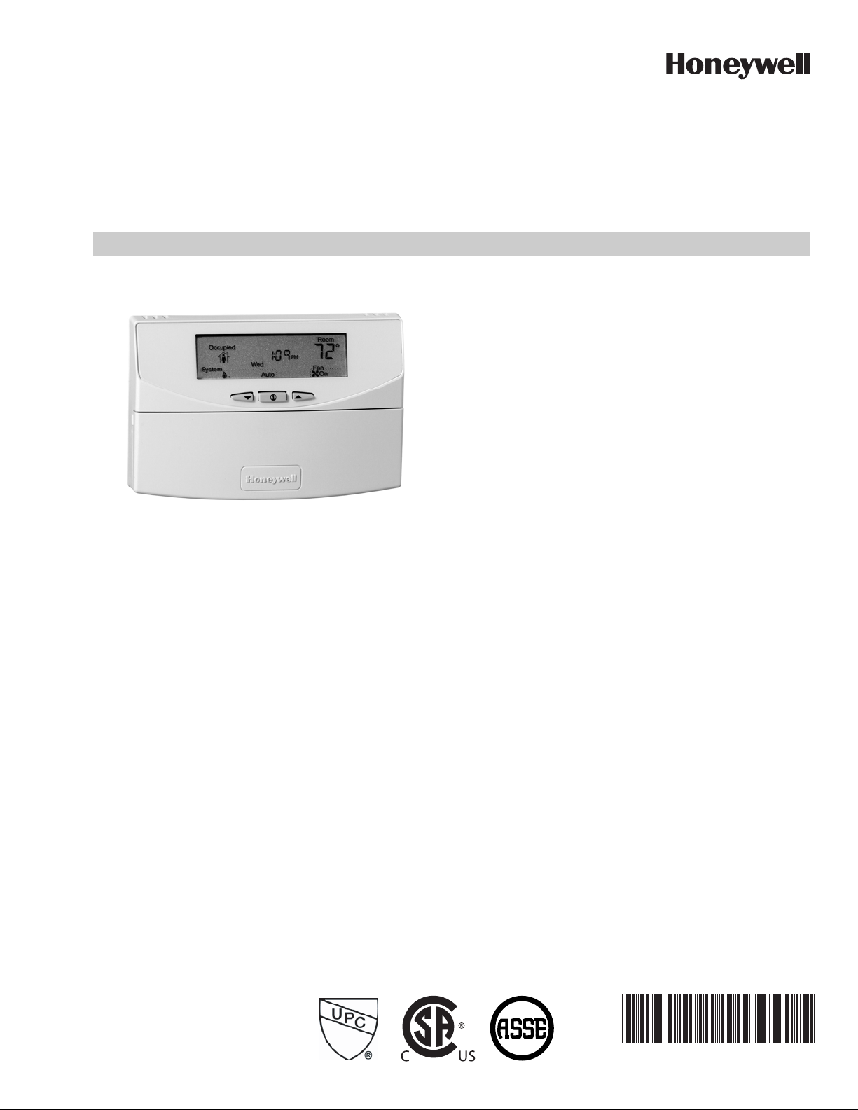
T7351 Commercial Programmable Thermostat
FOR SINGLE- OR MULTI-STAGE CONVENTIONAL/HEAT PUMP SYSTEMS
PRODUCT DATA
FEATURES
• Typically used in buildings (including: restaurants,
shopping malls, office buildings and banks) under
55,000 square feet.
• For single zone rooftop units, split systems, heat
pumps or hot/chilled water systems.
• 365-day programming.
• Two Occupied and two Not Occupied periods per day.
• Individual heat and cool setpoints available for
Occupied and Not Occupied periods.
• P+I+D control minimizes temperature fluctuations.
• Recovery ramp control automatically optimizes
equipment start times based on building load.
• Convenient overrides allow temporary setpoint
APPLICATION
The T7351 Commercial Programmable Thermostat controls
24 Vac commercial single zone heating, ventilating and air
conditioning (HVAC) equipment. The T7351 consists of a
thermostat and subbase. The thermostat includes the keypad
and display for 365-day programming. The subbase includes
equipment control connections. The subbase mounts on the
wall and the thermostat mounts to the subbase.
changes.
• Keypad multi-level lockout available with all models.
• Remote sensor capability for temperature (including
outdoor air and discharge air) and humidity sensors.
• Auxiliary subbase contact typically interface with a
Honeywell Economizer System (for total rooftop
control integration) or act as dehumidification output.
• Universal Versaguard Thermostat guards available.
Contents
Application ........................................................................ 1
Features ........................................................................... 1
Specifications ................................................................... 2
Ordering Information ........................................................ 2
Setting .............................................................................. 6
Installer Setup .................................................................. 7
Operation .......................................................................... 12
Troubleshooting Guide (Table 11) .................................... 17
Wiring Diagram (Figures 14 and 15) ................................ 19
63-2666-02
Page 2

T7351 COMMERCIAL PROGRAMMABLE THERMOSTAT
SPECIFICATIONS
IMPORTANT
The specifications given in this publication do not
include normal manufacturing tolerances. Therefore,
this unit might not exactly match listed specifications.
This product is tested and calibrated under closely
controlled conditions; minor performance differences
can be expected if those conditions are changed.
Table 1. T7351 Thermostat Features
Maximum Stages
Model Application
T7351F Conventional or
Heat Pump
a
This model is down-selectable and can be configured to control fewer stages than the maximum allowed.
b
Heat pump applications for this model have a maximum of two heat stages and two cool stages.
Mounting Means:
Mounts on subbase.
Subbase Mounts On:
Wall: Using two 5/8 in. long #6-32 screws (included).
Outlet Box: Using sheet metal screws.
Clock Accuracy at 77° F (25° C): ±1 min./month (30 days).
Minimum Stage Operation Time (fixed):
Minimum On
Heat: 1 minutes.
Cool: 3 minutes.
Minimum Off (Cool and Heat Pump): 1 minute.
Electrical Ratings:
Power: 24 Vac, 50/60 Hz.; 20 to 30 Vac, 50/60 Hz.
Input:
Temperature: 20K ohms.
Humidity: 0-10 Vdc.
Outdoor: 3000 PTC.
Discharge Air: 20K ohms.
Occupancy Sensor: Dry contact switching 30 Vdc at 1 mA.
All Relay Outputs (at 30 Vac):
Running: 1.5A maximum.
Inrush: 7.5A maximum.
System Current Draw (without load):
5 VA maximum at 30 Vac, 50/60 Hz.
NOTE: Relays are N.O. Single-Pole, Single-Throw (SPST).
3 (2)
b
Models: See Table 1.
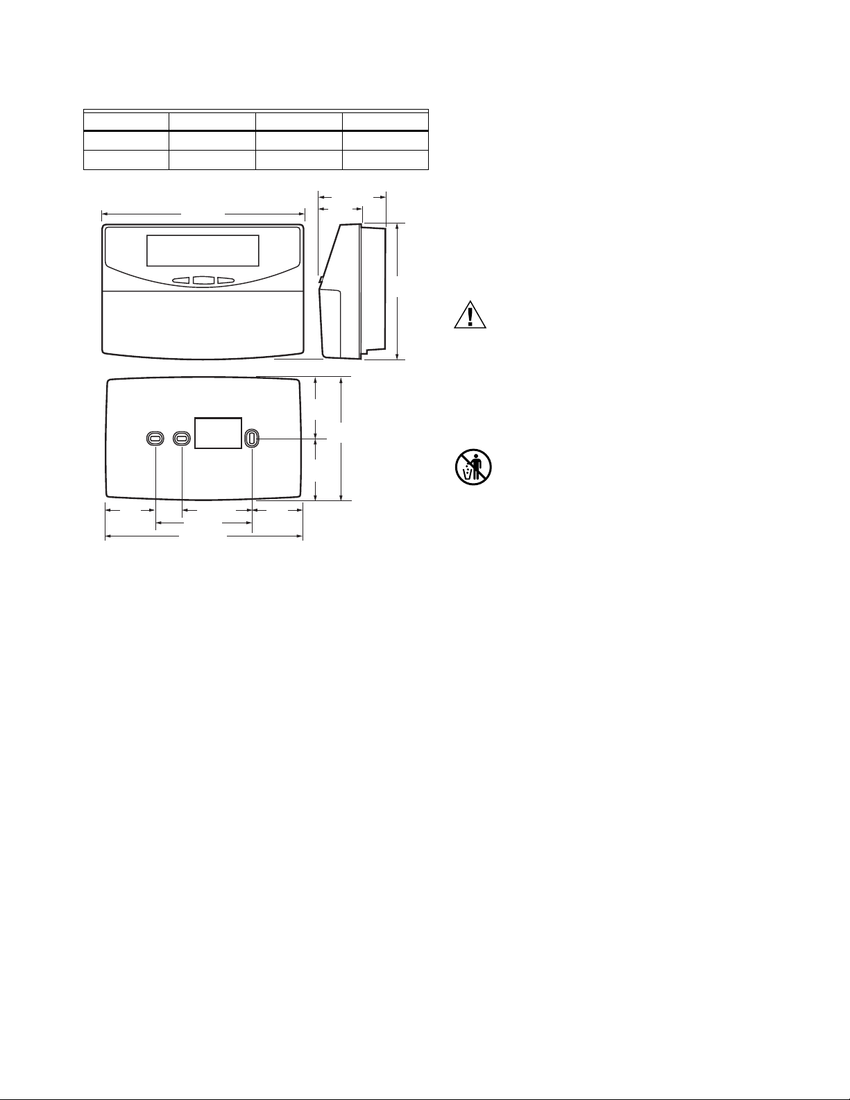
Dimensions: Refer to Fig. 1.
Finish (color): Trident White.
Batteries: No batteries required
a
Features
b
3 (4)
Outdoor Sensor Wiring: Requires 18 gauge wire.
Humidity Ratings: 5% to 90% RH, noncondensing.
Emergency Heat Indication:
Display indicates when Emergency Heat is activated (Em).
Temperature:
Ratings:
Display Accuracy: ±1° F (±1° C).
Setpoint:
Loss of Power: The thermostat maintains programmed times
NOTE: To achieve the 48-hour power-loss clock retention,
Approvals:
European Community Mark (CE) Listed.
UL 873 Recognized, NEC Class 2.
FCC Part 15 subpart J Class A.
cUL.
Humidity, Occupancy,
Outdoor, Discharge Air Capability
Operating Ambient: 30° to 110° F (-1° to 43° C).
Shipping: -30° to +150° F (-34° to +66° C).
Range:
Heating: 40° to 90° F (4° to 32° C).
Cooling: 45° to 99° F (7° to 37° C).
Deadband: 2° F (1° C).
Default Settings: Refer to Table 2.
and temperatures for the life of the product. Clock and day
information is retained for a minimum of 48 hours.
the T7351 must be powered for at least 5 minutes.
Auxiliary
RelayHeat Cool
Yes
ORDERING INFORMATION
When purchasing replacement and modernization products from your TRADELINE® wholesaler or distributor, refer to the
TRADELINE® Catalog or price sheets for complete ordering number.
If you have additional questions, need further information, or would like to comment on our products or services, please write or
phone:
1. Your local Honeywell Automation and Control Products Sales Office (check white pages of your phone directory).
2. Honeywell Customer Care
1885 Douglas Drive North
Minneapolis, Minnesota 55422-4386
In Canada—Honeywell Limited/Honeywell Limitée, 35 Dynamic Drive, Toronto, Ontario M1V 4Z9.
International Sales and Service Offices in all principal cities of the world. Manufacturing in Australia, Canada, Finland, France,
Germany, Japan, Mexico, Netherlands, Spain, Taiwan, United Kingdom, U.S.A.
63-2666—02
Page 3
T7351 COMMERCIAL PROGRAMMABLE THERMOSTAT
Table 2. Default Setpoints.
Control Occupied Not Occupied Standby
Heating 70° F (21° C) 55° F (13° C) 67° F (19° C)
Cooling 75° F (24° C) 85° F (29° C) 78° F (26° C)
2-3/16 (56)
2-1/32
(52)
2-1/32
(52)
1-9/16
(40)
4-1/16
(104)
M22432
4-1/2
(114)
SUBBASE
1-5/8
(42)
6-3/4 (171)
2-3/8 (60)
3-1/4 (83)
6-9/16 (166)
1-5/8
(42)
Fig. 1. Thermostat and Subbase Dimensions
in inches (mm).
Accessories:
Duct Discharge Air Sensors:
C7041B (6 or 12 in. [152 or 305 mm]),
C7041C (18 in. [457 mm]),
C7041J (12 ft. [3.66 m] averaging),
C7770A (8 in. [203 mm] probe).
Outdoor Air Sensors: C7089A, C7170A,
C7031G2014 (weatherproof).
Temperature Sensors (Remote): C7772A, TR21, TR22, TR23,
and TR24 series, TR21-WK, TR23-WK, T7771.
Economizer Logic Modules: W7210, W7212, W7215, W7459.
Humidity Sensors: H7625, H7635.
Others:
209541B FTT network termination module.
209651A Vertical Mounting Hardware Wallplate Adapter
(Trident white).
50000452-001 Troubleshooting Cable.
TG512 Universal Versaguard Thermostat guards.
INSTALLATION
When Installing this Product...
1. Read these instructions carefully. Failure to follow them
could damage the product or cause a hazardous
condition.
2. Check ratings given in instructions and on the product to
ensure the product is suitable for your application.
3. Installer must be a trained, experienced service
technician.
4. After installation is complete, check out product
operation as provided in these instructions.
CAUTION
Electrical Shock or Equipment Damage Hazard.
Can shock individuals or short equipment circuitry.
Disconnect power supply before installation.
IMPORTANT
All wiring must agree with applicable codes,
ordinances and regulations.
MERCURY NOTICE
If this control is replacing a control that contains
mercury in a sealed tube, do not place your old control
in the trash. Dispose of properly.
Contact your local waste management authority for
instructions regarding recycling and the proper disposal
of an old control. If you have questions, call Honeywell
Customer Care Center at 1-800-468-1502.
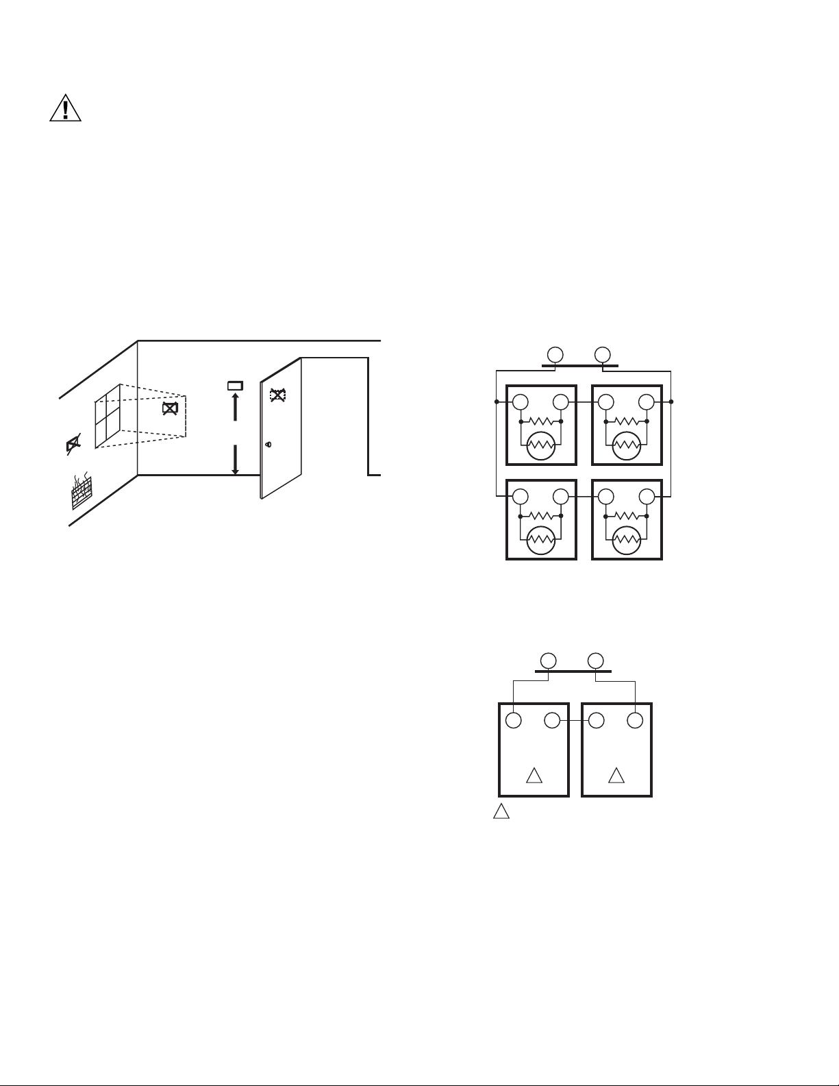
Location
Do not install the thermostat where it can be affected by:
— drafts, or dead spots behind doors and in corners.
— hot or cold air from ducts.
— radiant heat from sun or appliances.
— concealed pipes and chimneys.
— unheated (uncooled) areas such as an outside wall behind
the thermostat.
Subbase
WHEN USED TO SENSE ROOM TEMPERATURE
Install the thermostat about 5 ft. (1.5 m) above the floor in an
area with good air circulation at average temperature. (Refer to
Fig. 3.)
WHEN NOT USED TO SENSE ROOM TEMPERATURE
When using the remote-mounted temperature (and humidity)
sensor(s) to sense ambient conditions, install the thermostat in
an area that is accessible for setting and adjusting the
temperature and settings.
3 63-2666—02
Page 4
T7351 COMMERCIAL PROGRAMMABLE THERMOSTAT
CAUTION
Equipment Damage Hazard.
Can damage the TIM connection beyond repair.
Disconnect the TIM cable prior to opening or closing
the thermostat cover.
NOTE: Allow sufficient clearance below the thermostat to
plug in the TIM cable.
Install the remote-mounted sensor(s) about 5 ft. (1.5 m) above
the floor in an area with good air circulation at average
temperature. (See Fig. 2.)
NOTE: Only TR21 models with neither setpoint adjustment
nor bypass can be used for temperature averaging.
NO
NO
YES
5 FEET
(1.5 METERS)
NO
1. Position and level the subbase.
NOTE: A level wallplate is only for appearance. The
thermostat functions properly when not level.
2. Use a pencil to mark the mounting holes.
(Refer to Fig. 6.)
3. Remove the subbase from the wall and drill two 3/16 in.
(4.76 mm) holes in the wall (if drywall) as marked. For
firmer material such as plaster or wood, drill two 7/32 in.
(5.56 mm) holes.
4. Gently tap anchors (provided) into the drilled holes until
flush with the wall.
5. Position the subbase over the holes, pulling wires
through the wiring opening.
6. Loosely insert the mounting screws into the holes.
7. Tighten mounting screws.
SUBBASE
T4 T3
TR21
TT
TR21
TT
M4823A
Fig. 2. Typical Location of Thermostat or Remote-Mounted
Sensor.
IMPORTANT
To avoid electrical interference, which can cause
erratic performances, keep wiring runs as short as
possible and do not run thermostat wires adjacent to
the line voltage electrical distribution systems. Use
shielded cable (Belden type 8762 or equivalent for
2-wire). The cable shield must be grounded only at
the controlled equipment case.
Mounting Subbase
The subbase mounts horizontally or vertically.
IMPORTANT
• When using the internal temperature sensor, the
device must be mounted horizontally (with the LCD
facing upwards). Precise leveling is not needed.
• When using remote sensors, thermostat mounting
orientation does not matter.
Wall mounting (using standard drywall screws) is standard.
Mounting to a 2 in.(50.8 mm) by 4 in. (101.6 mm) wiring box
can be accomplished:
— for a horizontal box, no extra hardware is required.
— for a vertical box, part 209651A is required.
— Mount to European standard wall box 2.4 in. (having 61 mm
between mounting screws in a horizontal line) with or
without adaptive hardware.
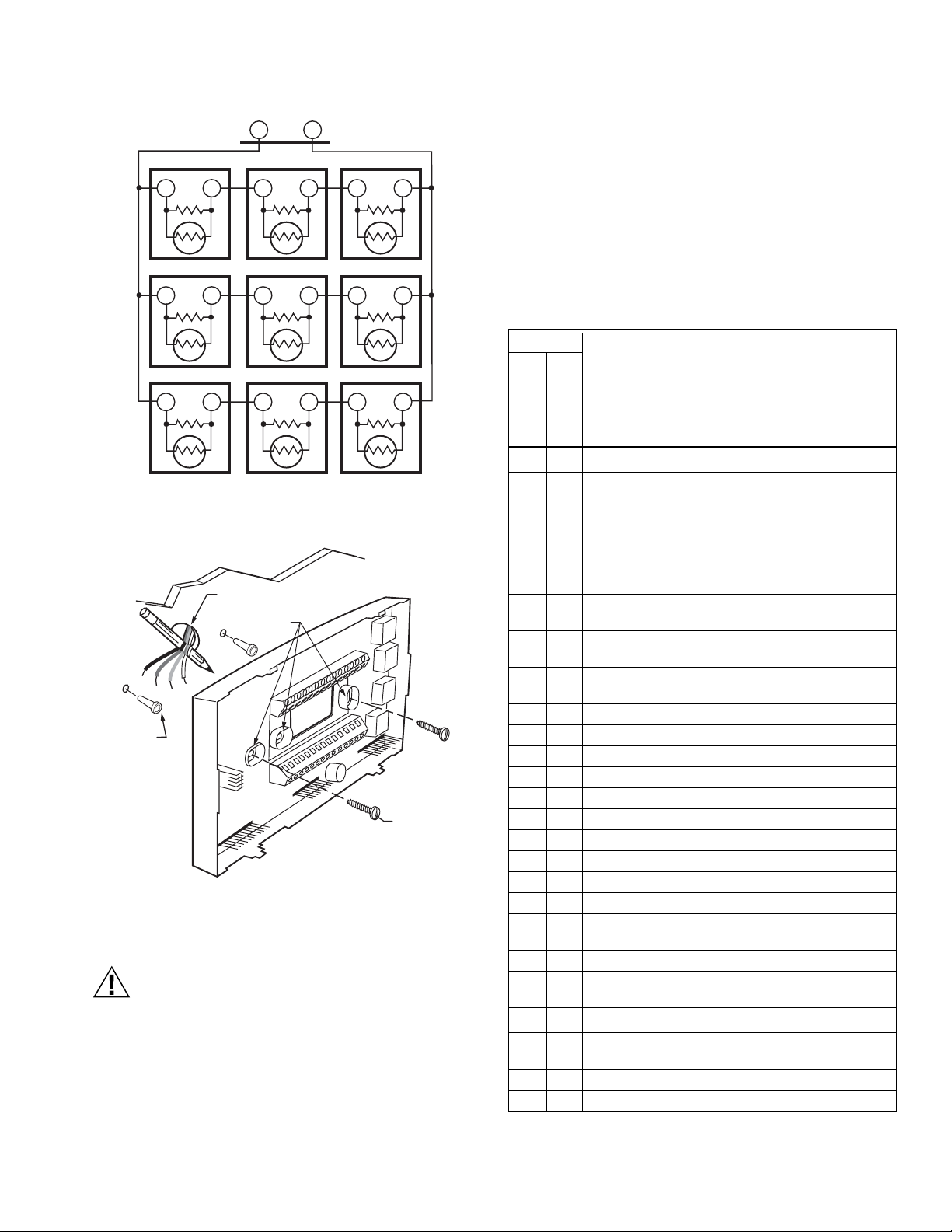
TR21
TT
TR21
TT
M29184
Fig. 3. Four TR21 Sensors providing a Temperature
Averaging Network for T7351 Thermostat.
T7350 SUBBASE
T4 T3
T4 T3
TR21-A
THE TR21-A IS A 10K OHM SENSOR.
1
T4 T3
1 1
TR21-A
M29256
Fig. 4. Two TR21-A Sensors Providing a Temperature
Averaging Network for T7351 Thermostat.
63-2666—02 4
Page 5
T7351 COMMERCIAL PROGRAMMABLE THERMOSTAT
SUBBASE
T4 T3
TR21
TT
TR21
TT
TR21
T
TR21
TT
TR21
TT
TR21
T
T
TR21
TT
TR21
TT
TR21
T
TT
M29257
Fig. 5. Nine TR21 Sensors Providing a Temperature
Averaging Network for T7351 Thermostat.
WIRES THROUGH WALL
MOUNTING
HOLES
WALL
ANCHORS
(2)
MOUNTING
SCREWS
Fig. 6. Mounting the Subbase.
Wiring
CAUTION
Electrical Shock or Equipment Damage Hazard.
Can shock individuals or short equipment circuitry.
Disconnect power supply before installation.
IMPORTANT
All wiring must comply with local electrical codes and
ordinances.
M19608
Follow equipment manufacturer wiring instructions when
available. Refer to the Wiring Diagram section for typical
hookups. A letter code is located near each terminal for
identification. Refer to Tables 3 for terminal designations.
1. Loosen subbase terminal screws and connect system
wires.
2. Securely tighten each terminal screw.
3. Push excess wire back into the hole in the wall.
4. Plug the hole with nonflammable insulation to prevent
drafts from affecting the thermostat.
Table 3. T7351 Subbase for Three-stage Heat, Three-stage
Cool Systems.
Terminal
Conventional
RCaRC
a
RH
RH
Heat Pump
a
24 VAC Cooling transformer.
a
24 VAC Heating transformer.
Description
X X Common.
aux aux Auxiliary relay.
W1 O/B Conventional: Stage 1 heating relay.
Heat Pump: Changeover relay for heating (B) or
b
cooling (O)
.
W2 W1 Conventional: Stage 2 heating relay.
Heat Pump: 1st Stage auxiliary heat relay.
Y1 Y1 Conventional: Stage 1 cooling relay.
Heat Pump: Stage 1 compressor relay.
Y2 Y2 Conventional: Stage 2 cooling relay.
Heat Pump: Stage 2 compressor relay.
AS AS Discharge Air Sensor connection (1).
AS AS Discharge Air Sensor connection (2).
OS OS Outdoor Air Sensor connection (1).
OS OS Outdoor Air Sensor connection (2).
G G Fan relay.
T3 T3 TR20 Series Remote Sensor connection (1).
T4 T4 TR20 Series Remote Sensor connection (2).
T5 T5 TR20 Series Remote Sensor connection (5).
T6 T6 TR20 Series Remote Sensor connection (9).
T7 T7 TR20 Series Remote Sensor connection (7).
W3 W2 Conventional: Stage 3 heat or stage 4 cool relay.
Heat Pump: 2nd Stage auxiliary heat relay.
Y3 — Conventional: Stage 3 cooling relay.
HS HS Humidity Sensor connection (signal: 0-10 Vdc).
TR23-H connection (11)
HC HC
Humidity Sensor connection (common).
c
HP HP Humidity Sensor connection (power). TR23-H
connection (12)
M M Motion Sensor connection (1).
M M Motion Sensor connection (2).
NOTE: Maximum (and recommended) wire size is 18-gauge
(ø 1.02 mm). Do not use wire smaller than 22-gauge
(ø 0.644 mm).
5 63-2666—02
Page 6

T7351 COMMERCIAL PROGRAMMABLE THERMOSTAT
a
Factory jumper between RC and RH for systems with one
transformer.
b
For changeover functional details, see Operation section.
c
HC connection is not needed when using a TR23-H sensor.
Mounting Thermostat on Subbase (Fig. 7)
With the subbase installed, mount the thermostat:
1. Engage the tabs at the top of the thermostat and subbase.
2. Swing the thermostat down.
3. Press the lower edge of the case to latch.
SETTING
Using Thermostat Keys
The thermostat keys are used to:
• set current time and day,
• program times and setpoints for heating and cooling,
• override the program temperatures,
• display present setting,
• set system and fan operation,
• perform simple configuration.
NOTE: Refer to Fig. 8 for keypad information.
NOTE: To remove the thermostat from the wall, first
pull out at the bottom of the thermostat; then
remove the top.
A. ENGAGE TABS AT TOP OF THERMOSTAT AND SUBBASE OR WALLPLATE.
B. PRESS LOWER EDGE OF CASE TO LATCH.
Setting Temperature
Refer to Table 2 for the default temperature setpoints. See
Programming section for complete instructions on changing
the setpoints.
Setting System and Fan
System default setting is Auto. Fan default setting is On.
NOTE: Use System and Fan keys to change settings.
System Settings
— Auto: Thermostat automatically changes between heating
and cooling based on indoor temperature.
— Cool: Thermostat controls only cooling.
— Off: Heating, cooling, and fan are all off.
— Heat: Thermostat controls only heating.
— Em Heat: Auxiliary heat serves as first stage. Compressor
stages are locked off.
Fan Settings.
— On: See Table 4.
— Auto: Fan always cycles with call for heating or cooling.
— Conventional: The equipment (i.e. plenum switch)
controls fan operation in heat mode. The thermostat
controls fan operation in cool mode.
— Electric Heat: The thermostat controls fan operation in
both heat and cool modes.
M19609
Fig. 7. Mounting Thermostat on Subbase.
63-2666—02 6
NOTE: Fan operation can extend (delay Off) after the
heating/cooling turns off:
— Heating choices are 0 or 90 seconds.
— Cooling choices are 0 or 40 seconds.
Page 7

T7351 COMMERCIAL PROGRAMMABLE THERMOSTAT
Table 4. T7351 Intelligent™ Fan ON control logic
Call for
Scheduled
Period
Occupancy
Motion Sensor
Signal
Effective
Occupancy Yes No
Heat/Cool
Notes
Occupied No Sensor Wired Occupied Fan On Fan On
Occupied Motion Sensed Occupied Fan On Fan On
Effective Occupancy is Standby. Standby
Occupied No Motion Sensed Standby Fan On
Fan Off
a
space is unoccupied. Fan is on only when there
setpoints are used and it assumes that the
is a call for heating or cooling.
Not Occupied No Sensor Wired Not Occupied Fan On
Not Occupied Motion Sensed Not Occupied Fan On
Not Occupied No Motion Sensed Not Occupied Fan On
a
In heat mode, when set for conventional heat, the equipment (i.e. plenum switch) could power the fan despite the T7350.
Fan Off
Fan Off
Fan Off
a
Occupancy sensor will only be active during
scheduled Occupied periods. During scheduled
a
Not Occupied periods, the effective occupancy
will always be Not Occupied.
a
Temperature
Occupied
HEAT HEATCOOL COOL
Not Occupied
Schedule
Start Time
Fig. 8. Thermostat Key Locations.
INSTALLER SETUP
For most applications, the thermostat factory settings do not
need to be charged. Review the factory settings in Table 2.
NOTE: When power is first applied to the thermostat, the
display will show all segments (See Fig. 9).
Temporary Standby
Not Occupied12
System
StartTime
MonTueWedTh uFri
Set ScheduleSet
EmHeat Off Cool Auto
Fig. 9. LCD Display of all Segments.
AM
PM
SatSunHol
Dehumid OnAuto
Room
MinsDays
Fan
%
M19611
Clear
Set Day/Time
Day Time
HEAT COOL
CopyNot OccupiedOccupiedDay
System Fan
Override
Temporary
Occupied
ON AUTO
Tem po rar y
Not Occupied
Run
Schedule
M19610
Setup Using Keypad
The installer uses the Installer Setup to customize the
thermostat to specific systems.
A combination of key presses are required to use the Installer
Setup features.
1. To enter the Installer Setup, press and hold both the Run
Schedule and the Copy keys until DEGREES 00 (or
DEGREES 01) displays.
NOTE: Installer Setup will display WAIT and is
unavailable for 30 seconds after power up.
2. To advance to the next Installer Setup number, press
.
CAUTION
Possible Equipment Damage.
Fan must be running when system is operating.
Heat pump and electric heat systems must be
configured correctly to prevent equipment damage
caused by the system running without the fan.
NOTE: Pressing Run/Copy again while in this mode
displays the T7351 firmware version number.
3. To return to a Setup item, cycle through the options.
4. To change a setting, use the up
or down key.
5. To exit the Installer Setup, press Run Schedule.
6. Display prompts SAV CFG (save configuration).
7 63-2666—02
Page 8

T7351 COMMERCIAL PROGRAMMABLE THERMOSTAT
a. If you want to save the new configuration, use the up
or down key to change NO to YES before
pressing Run Schedule.
b. If you want the configuration to remain as it was
before starting this change, ensure the
display indicates SAV CFG NO and press Run
Schedule.
NOTE: Installer Setup is automatically exited after five
minutes with no key pressed. Upon this automatic
exit, all changes are lost.
Configuration
Configuration can be done with the keypad using the Installer Setup (ISU).
Table 5. Installer Setup.
Text Default Choices Notes
DEGREES 0 0 -1 Degree Temperature Format
CLOCK 0 0 - 1 Clock Display Format
KEYLOCK 0 0 - 3 Keypad Lockout Level
HEATPMP 0 0 - 2 Application Type Selection
COOLSTG 1 0 - 4 Number of Cooling Stages
HEATSTG 1 0 - 3 Number of Conventional Heating Stages (Not available if Heat Pump is selected)
AUX STG 0 0 - 2 Number of Heat Pump Heating Stages (Only shown when Heat Pump is selected)
AUX CON 0 0 - 3 Aux Contact Functionality
WALLMOD 0 0 - 3 Remote Room Sensor Selection
0: Degrees F
1: Degrees C
0: 12 hour
1: 24 hour
0: None
1: Lockout all keys except Set Day, Set Time, Set Date, Set Holidays, Temporary
Occupied, Temporary Not Occupied, System, Fan, Up, Down and Information
2: Lockout all keys except Set Day, Set Time. Set Date, Set Holidays, Temporary
Occupied, Temporary Not Occupied, Up, Down and Information
3: Lockout all keys except Information
0: Conventional
1: Heat Pump - Cooling (Energize O/B on call for cool)
2: Heat Pump - Heating (Energize O/B on call for heat)
0: 0 Stages of Cooling
1: 1 Stages of Cooling
2: 2 Stages of Cooling
3: 3 Stages of Cooling (Not available if Heat Pump is selected)
4: 4 Stages of Cooling (W3 will be used as 4th stage relay) (Not available if Heat Pump is
selected)
0: 0 Stages of Heating
1: 1 Stages of Heating
2: 2 Stages of Heating (This is the max if 4 cooling stages is selected)
3: 3 Stages of Heating
0: 0 Aux Stages
1: 1 Aux Stages
2: 2 Aux Stages
0: Time of Day
1: Economizer
2: Dehumid - Hot Gas Bypass
3: Simple Dehumid
0: Local sensor only
1: TR21/TR24 and T7770A/D (Remote Sensor, No Remote Setpoint, Bypass 0)
2: TR22/TR23 and T7770B/C (Remote Sensor, Remote Setpoint, Bypass 0)
3: T7771 (Remote sensor, Remote Setpoint, Bypass 1)
(Bypass 0 means that by pressing the override button the thermostat goes from
unoccupied to occupied and the LED will light up and the temporary occupied timer will
begin. If the button is pressed again, the timer will restart.)
(Bypass 1 means that by pressing the override button a second time the thermostat can
return to the unoccupied period.)
63-2666—02 8
Page 9

T7351 COMMERCIAL PROGRAMMABLE THERMOSTAT
Table 5. Installer Setup. (Continued)
Text Default Choices Notes
OATSENS 0 0 - 1 Outdoor Air Sensor Selection
0: None
1: Remote Outdoor Air Sensor
DATSENS 0 0 - 1 Discharge Air Sensor Selection
0: None
1: Remote Discharge Air Sensor
HUMSENS 0 0 - 2 Room Humidity Sensor selection
0: None
1: On Board Sensor
2: Remote Sensor
OCCSENS 0 0 - 1 Occupancy Sensor Selection
0: None
1: Remote Occ Sensor
FAN HT 0 0 - 1 Fan Operation on Heat
0: Conventional (Equipment controls Fan)
1: Electric (Thermostat turns on Fan with call for Heat)
XFAN HT YES YES or NO Extended Fan on Heat
NO: None
YES: 90 seconds
XFAN CL NO YES or NO Extended Fan on Cool
NO: None
YES: 40 seconds
STRTDEL 0 0 - 15 Sequential Start Delay
0 to 150 seconds in 10 second increments
ADVANCE NO YES or NO Advanced Settings
NO: Hide
YES: Show
TMP LIM 3 0 - 5 Temporary Setpoint Adjustment
0: 0 Deg. F
1: 1 Deg. F
2: 2 Deg. F
3: 3 Deg. F
4: 4 Deg. F
5: 5 Deg. F
TMP OCC 3 1 - 8 Temporary Occupied Duration
1 to 8 hours
TMP CAL 0 -4 - 3 Temporary Display Adjustment
0 - 3 = 0 to 3 DDF
4 - 7 = -4 to -1 DDF
MINCOOL 45° F
(7° C)
MAXHEAT 90° F
(32° C)
45° - 99° F
(7° - 37° C)
40° - 90° F
(4° - 32° C)
Min Cool Setpoint
Max Heat Setpoint
HEATLCK NO YES or NO Heating Lockout (Only displayed if Outdoor Air Sensor is selected)
NO: None
YES: Enabled
HTLCKSP 70° F
(21° C)
-40° - 120 ° F
(-40° - 49° C)
Heating Lockout Temperature
(Display only if Remote Outdoor Air Sensor is configured)
COOLLCK NO YES or NO Cooling Lockout (Only displayed if Outdoor Air Sensor is Selected)
NO: None
YES: Enabled
CLLCKSP 35° F
(2° C)
-40° - 120° F
(-40° - 49° C)
Cooling Lockout Temperature
(Display only if Remote Outdoor Air Sensor is configured)
DAT LL NO YES or NO Discharge Low Limit (Only displayed if Discharge Air Sensor is Selected)
NO: None
YES: Enabled
DATLLSP 45° F
(7° C)
35° - 60° F
(2° - 16° C)
Discharge Low Temp Limit
(Display only if Discharge Sensor is configured)
9 63-2666—02
Page 10

T7351 COMMERCIAL PROGRAMMABLE THERMOSTAT
Table 5. Installer Setup. (Continued)
Text Default Choices Notes
DAT HL NO YES or NO Discharge High Limit (Only displayed if Discharge Air Sensor is Selected)
DATHLSP 110° F
(43° C)
DEHUMID 0 0 - 5 Dehumidification
DEH MIN 5 5 - 15 Dehumidify Minutes On
DEH TMP 2 1 - 5 Dehumidify Temp Reset
MINHTRT 5 0 - 20 DDF/HR Minimum Heat Recovery Ramp Rate
MAXHTRT 8 0 - 20 DDF/HR Maximum Heat Recovery Ramp Rate (Only Displayed if Outdoor Sensor is Selected)
MINHTOA 0° F
(-18° C)
MAXHTOA 40° F
(4° C)
MINCLRT 3 0 - 20 DDF/HR Minimum Cool Recovery Ramp Rate
MAXCLRT 6 0 - 20 DDF/HR Maximum Cool Recovery Ramp Rate (Only Displayed if Outdoor Sensor is Selected)
MINCLOA 90° F
(32° C)
MAXCLOA 70° F
(21° C)
DSTMON1 3 0 - 12 DLS Spring Month
DSTDAY1 40 0 - 31, 32 - 74 DLS Spring Day
DSTMON2 11 0 - 12 DLS Fall Month
DSTDAY2 33 0 - 31, 32 - 74 DLS Fall Day
HT RESP 1 0 - 3 0: Standard - 3 cph
CL RESP 0 0 - 1 0: Standard - 3 cph
65° - 140° F
(18° - 60° C)
-20° - 120° F
(-29° - 49° C)
-20° - 120° F
(-29° - 49° C)
-20° - 120° F
(-29° - 49° C)
-20° - 120° F
(-29° - 49° C)
NO: None
YES: Enabled
Discharge High Temperature Limit
(Display only if Discharge Sensor is configured)
0: None
1: MinOn Time
2: Reset Temp Setpoint
3: Reset w/ MinOn
4: Reheat
5: Reheat w/ Min On
Minimum Heat Outdoor Air Temperature (Only Displayed if Outdoor Sensor is Selected)
Maximum Heat Outdoor Air Temperature (Only Displayed if Outdoor Sensor is Selected)
Minimum Cool Outdoor Air Temperature (Only Displayed if Outdoor Sensor is Selected)
Maximum Cool Outdoor Air Temperature (Only Displayed if Outdoor Sensor is Selected)
(DayLight Savings options only display when Date is valid)
0 - 31 = Day of Month
32 = Last Day of Month
33 = First Sunday
etc…
0 - 31 = Day of Month
32 = Last Day of Month
33 = First Sunday
etc…
1: Medium - 6 cph
2: Fast - 9 cph
3: Super Fast - 20 cph
1: Fast - 4 cph
Holidays and 365 - Day Clock
The T7351can be configured to schedule up to 10 separate
holidays, each with a duration of up to 99 days. To enable this
function, the user must set the date:
1. Press Set Day and Set Time keys simultaneously.
2. Use the Up/Down keys to set the date to YES, then
press the key.
3. Use the Up/Down keys to set the month, then press the
key.
63-2666—02 10
4. Use the Up/Down keys to set the day, then press the
key (Refer to Table 4 for valid day choices).
5. Use the Up/Down keys to set the year, then press the
key.
Holidays can be set in the following manner:
1. Press the “Temporary Occupied” and Temporary Not
Occupied” keys simultaneously.
2. The month (MON) of the first holiday is then displayed
(00 means the holiday is ignored).
3. Use the Up/Down keys to set the month, then press the
key.
Page 11

T7351 COMMERCIAL PROGRAMMABLE THERMOSTAT
4. Use the Up/Down keys to set the day, then press the
key (Refer to Table 6 for valid day choices).
5. Use the Up/Down keys to set the duration.
Table 6. Valid Day Values.
Value Description Value Description
1 to 31 Day of month 42 Second Tuesday 53 Third Saturday 64 Fifth Wednesday
32 Last Day of Month 43 Second Wednesday 54 Fourth Sunday 65 Fifth Thursday
33 First Sunday 44 Second Thursday 55 Fourth Monday 66 Fifth Friday
34 First Monday 45 Second Friday 56 Fourth Tuesday 67 Fifth Saturday
35 First Tuesday 46 Second Saturday 57 Fourth Wednesday 68 Last Sunday
36 First Wednesday 47 Third Sunday 58 Fourth Thursday 69 Last Monday
37 First Thursday 48 Third Monday 59 Fourth Friday 70 Last Tuesday
38 First Friday 49 Third Tuesday 60 Fourth Saturday 71 Last Wednesday
39 First Saturday 50 Third Wednesday 61 Fifth Sunday 72 Last Thursday
40 Second Sunday 51 Third Thursday 62 Fifth Monday 73 Last Friday
41 Second Monday 52 Third Friday 63 Fifth Tuesday 74 Last Saturday
.
Table 7. T7351 Key Function Summary.
Grouping Button Definition
Information Down Arrow Lowers setpoint, day, or time. When setting times or temperatures, hold key down to
Information Obtains information (where humidity “high-limit” can be set), cycles through setup
Up Arrow Raises setpoint, day, or time. When setting times or temperatures, hold key down to
Temperature Occupied
Heat
Occupied
Cool
Not Occupied
Heat
Not Occupied
Cool
Set Day Sets day of week. Tapping key with 'Set Value' segment on increases current day (same
Time Sets time. Tapping key with “Set Value” segment on increases time in one hour
Override Temporary
Occupied
Tem p or a ry No t
Occupied
Schedule Day Selects day schedule to modify. (Used also with copy key.)
continuously decrease value. Also can make temporary change in temperature setpoint.
options.
continuously increase value. Also can make temporary change in temperature setpoint.
Sets Occupied Heat setpoint.
Sets Occupied Cool setpoint.
Sets Not Occupied Heat setpoint.
Sets Not Occupied Cool setpoint.
effect as Up Arrow key).
increments.
Temporary occupied setting for length of time defined by installer. User can modify
setpoints.
Sets holiday length. User selects number of days (“0”-”99”), or “---” for continuous
override.
The first holiday is now set and pressing the key will take
you to programming the second holiday (denoted by the
number 2 on the screen)
Occupied Selects occupied event start times for specified day. Repeatedly press this key to toggle
Not Occupied Selects not occupied event start times for specified day. Repeatedly press this key to
Clear Start Time Clears start time for specified period and day.
Copy Copies schedule from one day to another.
System Selects System Mode. Toggles through Em Heat, Off, Cool, and Auto.
between two occupied events.
toggle between two not occupied events.
11 63-2666—02
Page 12

T7351 COMMERCIAL PROGRAMMABLE THERMOSTAT
Table 7. T7351 Key Function Summary. (Continued)
Grouping Button Definition
Schedule Fan
Selects fan operation mode. Toggles between On and Auto.
a
Run Schedule Resumes running schedule (cancels Temporary Occupied action, Holiday, and/or
a
On: Continuous fan operation during occupied periods. During not occupied periods and in standby mode when no motion is
sensed, fan cycles with call for heat or cool.
Auto: Fan cycles with call for heat or cool during all periods. (See Product Data Sheet, form 63-2605, for more details).
NOTES: The display returns to default screen after pressing Run Schedule (or after a period of time without keypress):
— ten seconds: when returning from temporary setpoint changes, info screen, temp occ, and temp not occ.
— one minute: when returning from setting clock/day.
— ten minutes: when returning from System Checkout.
— five minutes: when returning from all other modes.
Special Functions
Restore Factory Configuration (Run/Clear)
IMPORTANT
Get Factory Schedule (Info/Clear)
Performing this operation reverts the schedules to the factory
defaults:
Test Mode (Occupied/Not Occupied/
Schedule Day)
This operation erases current configuration and
restores factory defaults for all configuration,
parameters, setpoints and schedules. To regain the
old requires device reconfiguration.
1. Press both Run Schedule and Clear Start Time.
2. The display gives the option to revert to FAC CFG.
a. To restore the factory defaults, press up
down
b. To cancel this option, ensure the display
3. Press Run Schedule.
1. Press both Info and Clear Start Time.
2. The display gives the option to revert to FAC SCH.
a. To restore the factory schedule, press up
b. To cancel this option, ensure display indicates NO.
3. Press Run Schedule.
until the display indicates YES.
indicates NO.
until the display indicates YES.
down
Temporary setpoint changes.)
NOTES:
Save User Schedule (Info/Copy)
or
or
Performing this operation saves the current schedule
(including holidays) to memory, overwriting the old saved
schedule:
Get User Schedule (Info/Run)
Getting the user schedule restores the schedule (including
holidays) from saved memory, overwriting the schedule
currently in use:
a. To enter test mode, press up
display indicates IN TEST.
b. To cancel this option, ensure display indicates NO
TEST.
3. Press Run Schedule.
— To verify whether or not the system test is still
active, repeat the above process.
— The system test times out after ten minutes with no
key pressed.
1. Press both Info and Copy.
2. The display gives the option to revert to SAV SHD.
a. To save the current schedule, press up
down
until the display indicates YES.
b. To cancel this option, ensure display indicates NO.
3. Press Run Schedule.
1. Press both Run Schedule and Info.
2. The display gives the option to GET SHD.
a. To retrieve the saved schedule, press up
b. To cancel this option, ensure display indicates NO.
3. Press Run Schedule
until the display indicates YES.
down
or downuntil the
or
or
CAUTION
Possible Equipment Damage.
Equipment damage can result if compressor is
cycled too quickly.
The minimum off time for compressors is bypassed
during Test Mode. Equipment damage can occur if the
compressor is cycled too quickly.
Use the Test Mode to check the thermostat configurations and
operation. To start the system test:
1. Press Schedule Day, Occupied and Not Occupied
simultaneously.
2. The display gives the option to TEST.
63-2666—02 12
OPERATION
Startup Operation
Upon initial thermostat power-up, a startup and initialization
program begins. This startup occurs only on initial power-up.
After total loss of power for an extended period, the current
time and day can be lost (requiring reset). However, the
thermostat retains the user program.
NOTE: With no program set, the thermostat controls to the
Occupied default setpoints of 70° F (21° C) for heat
and 75° F (24° C) for cool.
Page 13

T7351 COMMERCIAL PROGRAMMABLE THERMOSTAT
A
T7351 Relay Logic
All T7351 model thermostats contain at least four switching
relays. In conventional applications, the relays control first
stage cooling, first stage heating, fan, and auxiliary. In heat
pump applications, the relays control the heat pump
compressor, changeover, fan, and emergency heat.
O/B Terminal for Heat or Cool Changeover
The O/B terminal controls heat pump changeover. The default
operation is for the terminal to be powered when calling for
heat (or while the most recent call was for heat). This
corresponds to a typical B terminal.
NOTE: The O/B terminal can be configured to operate as a
typical O terminal (powered on call for cool).
Emergency Heat
With the system set for Em Heat, auxiliary heat serves as
stage one; compressor stages are locked off. The fan cycles
with the auxiliary heat.
Equipment Protection
As part of the operational sequence, the T7351
microprocessor incorporates cycle rate, and minimum on and
off times for all heating and cooling stages. This extends
equipment life as it prevents rapid cycling of equipment.
NOTE: Minimum on and off times are fixed.
Cycle Rates
The thermostat control algorithm maintains the temperature by
cycling stages of heating or cooling to meet setpoint. Cycle
rates, in cycles per hour (cph) are set in the installer setup.
NOTE: In the items that follow, the term “error” refers to the
difference between the measured space temperature
and the current actual space temperature setpoint:
— The Throttling Range (TR), also called Proportional Gain,
determines the impact of the error on the output signal.
Decreasing TR amplifies the error effect; that is, for a given
error, smaller TR causes higher output signal.
— The Integral Time (IT), also called Integral Gain,
determines the impact of the error-over-time on the output
signal. Error-over-time has two components making up its
value: amount of time the error exists; and size of the error.
The higher the IT, the slower the control response. In other
words, a decrease in IT causes a more rapid change to the
output signal.
— The Derivative Time (DT), also called Derivative Gain,
determines the impact of the error rate on the output signal.
The error rate is how fast the error value changes. It can
also be the direction the space temperature is going, either
toward or away from the setpoint, and its speed—rapid or
slow. A decrease in DT causes, for a given error rate, a
greater effect on output signal.
Recovery Ramping Logic
The T7351 incorporates a ramping feature that gradually
changes the space setpoints. During recovery operation, the
setpoint changes at a rate in degrees per hour depending on
the outdoor air temperature. If there is no outdoor air
temperature sensor available, the minimum ramp rate is used.
When recovering in heating, the control point raises gradually,
maximizing the use of the more economical first stage heat to
bring the sensed temperature to the desired comfort setpoint.
This minimizes using the typically more expensive later
stage(s) of heat.
NOTE: See Fig. 10 for a pictorial representation of the heat
ramp rate determination.
NOTE: Defaults are: heat: 6cph, cool: 3cph.
P+I+D Control
The T7351 microprocessor-based control requires that the
user understands temperature control and thermostat
performance. A conventional electromechanical or electronic
thermostat does not control temperature precisely at setpoint.
Typically, there is an offset (droop) in the control point as the
system load changes. This is a phenomenon that most people
in the industry know and accept.
IMPORTANT
• P+I+D (Loop Tuning) parameters are optimized for
proper operation of a vast majority of HVAC systems.
Only when completely certain of necessary and
proper changes should you alter these values.
• Improper changes result in poor system performance
and equipment problems such as compressor short
cycling. Other problems include wide swings in space
temperature and excessive overdriving of modulating
outputs.
All adjustments to Loop Tuning parameters should be gradual.
After each change, allow the system to stabilize to accurately
observe the effects of the change. Then, as needed, make
further refinements until the system operates as desired.
If adjustment of PID parameters is required, use the following:
Recovery Ramping for Conventional Systems
HEAT RECOVERY
RAMP RATE
(DEGREES/HOUR)
MaxHtRamp
MinHtRamp
OUTDOOR AIR
TEMPERATURE
OaTempMinHtRamp OaTempMaxHtRamp
Fig. 10. Heat Setpoint Ramping for Conventional Systems.
NOTES:
M10109
13 63-2666—02
Page 14

T7351 COMMERCIAL PROGRAMMABLE THERMOSTAT
— Recovery ramping applies between scheduled
heat or cool setpoint changes from not occupied to
standby and not occupied to occupied.
— Other setpoint changes use a setpoint step
change.
Recovery Ramping for Heat Pump Systems
During recovery with heat pump equipment, the heating
setpoint is split into a heat pump setpoint for compressors, and
two auxiliary heat setpoints for the auxiliary heat stages. (Refer
to Fig. 11 for the various setpoints.)
OCCUPIED
SETPOINT
NOT OCCUPIED
SETPOINT
RECOVERY TIME
Fig. 11. Heat Setpoint Ramping for Heat Pump Systems.
Heat pump ramping for heating proceeds
as follows:
1. The heat pump setpoint begins to ramp until the room
temperature and the compressor ramp intersect.
2. At this point, the heat pump setpoint performs a step
change to the Occupied (or Standby) setpoint and all
auxiliary heat stages are disabled.
NOTE: The heat pump setpoint remains here for the
rest of the Not Occupied period.
HEAT PUMP SETPOINT
(FOR COMPRESSORS)
NORMAL
RECOVERY RAMP
AUX HEAT
STAGE 2 RAMP
AUX HEAT
STAGE 1 RAMP
SPACE
TEMPERATURE
OCCUPIED
TIME
M19877
NOTE: The setpoint used during the cool recovery period is
similar to the heat mode in Fig. 10, except the slope
of the line reverses for cooling.
COOL RECOVERY
RAMP RATE
(DEGREES/HOUR)
MaxClRamp
MinClRamp
OUTDOOR AIR
TEMPERATURE
OaTempMinClRamp OaTempMaxClRamp
M10111A
Fig. 12. Setpoint Ramping Parameters with Ramp Rate
Calculation.
Advantages:
• Comfort setting is achieved at the programmed time and
maintained regardless of weather conditions; occupants are
comfortable.
• Drafts from low-temperature discharge air are minimized
during Occupied periods.
• Use of the more economical first stage of heat is maximized
during recovery, minimizing use of the expensive later heat
stage(s).
• Comfort and energy savings can be achieved in both
heating and cooling.
• Heat cycling reduced, extending equipment life.
Auxiliary Relay
The auxiliary relay can be used with a variety of controls:
• Time-of-day (TOD).
• Economizer minimum position control.
• Dehumidification (see Dehumidification section).
3. The stage one auxiliary heat ramp is calculated based on
a steeper slope starting 1° F (0.5° C) below the not
occupied setpoint.
4. When the room temperature intersects this auxiliary heat
ramp, the first stage of auxiliary heat is enabled.
5. The stage two auxiliary heat ramp is calculated based on
an even steeper slope starting 2° F (1° C) below the not
occupied setpoint.
6. When the room temperature intersects this auxiliary heat
ramp, the second stage of auxiliary heat is enabled.
During the cool recovery period, the setpoint changes at a rate
in degrees per hour relative to the outdoor air temperature. If
there is no outdoor air temperature sensor available, the
minimum ramp rate is used.
See Fig. 12 for the various setpoints.
NOTE: For cooling, the same method is used in both
conventional and heat pump systems.
63-2666—02 14
Relay for Time-Of-Day (Table 8)
Time-of-day (TOD) is the Auxiliary Relay default configuration.
TOD logic operates strictly according to programming:
— Occupied: Relay contacts closed.
— Not Occupied: Relay contacts open.
— Standby (Scheduled): Relay contacts closed.
Relay for Economizers
Mechanical cooling is often used with outside temperatures in
the 50° F (10° C) to 60° F (16° C) range and humidity below 50
percent. In central and northern climates, hundreds of hours
fall into this temperature category. By permitting 80 to 100
percent outside air into the system, mechanical cooling may
not be needed at all, particularly during Spring and Fall.
Economizers take advantage of outside air. The typical
economizer consists of an outside air damper, motor, outdoor
air changeover control and a minimum position potentiometer.
The motor controls the dampers. Suitability of the outside air
for cooling is determined by the outdoor air changeover
Page 15

T7351 COMMERCIAL PROGRAMMABLE THERMOSTAT
control. The potentiometer adjusts the minimum position of the
economizer dampers, which provide a minimum amount of
fresh air for ventilation.
The economizer reduces compressor run time, thereby saving
energy and extending compressor life. The drawback to using
the economizer is that during the Not Occupied period, if there
is no call for cool or outdoor air is not suitable for free cooling,
the economizer is controlled to minimum position. This position
allows some percentage of outdoor air to enter the building,
regardless of air suitability. The situation can cause the heating
or cooling to run more often than when only suitable air is
permitted to enter the building.
Table 8. T7351 Auxiliary Relay Logic (Economizer and TOD)
Occupancy Auxiliary Contacts
Scheduled
Period
Occupied No Sensor
Occupied Motion Sensed Occupied
Occupied No Motion
Not Occupied No Sensor
Not Occupied Motion Sensed Not
Not Occupied No Motion
Motion Sensor
Signal
Wired
Sensed
Wired
Sensed
Effective
Occupancy Economizer TOD
Occupied
Closed
Closed
b
b
Standby Open; Closed only
during calls for cool
Not
Occupied
Open; Closed only
during calls for cool
Open; Closed only
Occupied
Not
Occupied
during calls for cool
Open; Closed only
during calls for cool
The T7351 can take advantage of an economizer by closing
the auxiliary relay contacts to control the economizer minimum
position potentiometer. (See Table 8 for details.)
— Powered: Allows normal economizer operation.
— Unpowered: Disables the economizer minimum position.
The lack of power causes the economizer to drive dampers
fully closed instead of staying at minimum open position.
This reduces the possibility of unsuitable outdoor air
entering the building, which lowers the internal load on the
HVAC system and saves additional energy.
Notes
Closed
Closed
Open Effective Occupancy is Standby. Standby
a
setpoints are used and it assumes that the space
is unoccupied. Economizer relay is energized
only on calls for cooling.
Open
a
Occupancy sensor will only be active during
Open
a
scheduled Occupied periods. During scheduled
Not Occupied periods, the effective occupancy
will always be Not Occupied.
Open
a
a
Unless otherwise, noted, Economizer logic ignores calls for heat. The Economizer relay will be energized during calls for cooling.
b With fan set to AUTO and call for neither heat nor cool, the relay is open in order to disable damper minimum position.
Other Uses for the Auxiliary Relay
Examples of other uses of the auxiliary relay are hot water
heaters, lighting, or baseboard heat. The additional loads are
connected to the auxiliary relay contacts on the subbase. The
contacts are rated for 1.5A at 30 Vac, but can be adapted to
higher current applications using an external relay
(See Fig. 13).
T7350A,B,D,M SUBBASE
AUX
AUXILIARY
RELAY
CONTACT
1
RH
X
RELAY REQUIRED (R8222 OR SIMILAR).
1
TO
LOAD
M19613
Default Auxiliary Relay Operations
Unless configured as a stage of heating or cooling, terminals
W2, W3, and Y3 operate for specific auxiliary functions. Each
output takes on different auxiliary functions depending on
configuration for Conventional or Heat Pump operation. See
Table 9 for details.
NOTE: The default functions cannot be modified. They are
limited to firmware version 1.3.0 or higher.
Fig. 13. Using T7351 Models with an External Relay (with
loads greater than 1.5A).
15 63-2666—02
Page 16

T7351 COMMERCIAL PROGRAMMABLE THERMOSTAT
Table 9. Default Auxiliary Relay Operations.
Heat Pump or
Conventional
Contact Not Used as
Heat or Cool Stage Contact Configuration of Contact Not Used as Stage
Heat Pump Y3 Simple
Dehumidification
W2 not aux heat Economizer Time of Day Economizer Economizer
Conventional W3 not Simple
Dehumidification
Y3 not (W3 not) Economizer Time of Day Time of Day Economizer
Y3 not (W3 used) Simple
Dehumidification
Simple
a
Dehumidification
Simple
a
Dehumidification
Simple
a
Dehumidification
Time of Day Time of Day
a
Simple
a
Dehumidification
a
Simple
a
Dehumidification
a
Time of Day
Time of Day
Auxiliary Contact Configuration Time of Day Economizer Hot Gas Bypass
Dehumidification
a
Simple dehumidification uses a normally closed contact. The relay is closed when humidity is below the high limit. When the
Simple
Dehumidification
humidity is above the high limit, the contact is open.
Dehumidification
There are five methods through which the T7351 can control
for dehumidification. Three of them modify the control
algorithm, thus providing limited dehumidification through
cooling. The other two use the auxiliary output to control
another device.
NOTE: The dehumidification high limit can be set within the
range of 10 to 90 percent relative humidity.
IMPORTANT
At times during Reheat dehumidification, the T7351
operates heating and the cooling simultaneously. This
is normal.
NOTES:
— The heat stage never energizes during Reheat if
more than one cool stage is on.
— Reheat mode cannot occur during heating.
RESET TEMP SETPT
Control Through Cooling
Configure using some combination of the following:
— Minimum On.
— Reheat.
— Reset.
NOTES:
— These methods operate only during cooling.
— Selecting both Reheat and Reset can cause
frequent setpoint adjustments. This selection
is not recommended.
MIN ON TIME
Dehumidifies by increasing the compressor minimum on time
(normally 3 minutes) by a programmable amount. This is useful
The room temperature set point resets to a specified number of
degrees below the actual set point when room relative humidity
(RH) rises above humidity high limit. The default value is 2
degrees.
Though this may not technically reduce RH, it reduces the dew
point to provide the customer with a sense of comfort due to a
lower temperature setting in the room.
As long as RH stays above humidity high limit, this set point is
maintained.
NOTE: Hysteresis and a minimum timer prevent the set point
from short interval alternation (between standard and
reset set points).
with oversized systems in that it forces the coils to cool to a
point where dehumidification can occur.
Options Utilizing Auxiliary Output
There are two dehumidification options that utilize the auxiliary
NOTES:
— Can force wider temperature swings by cooling
when setpoint control does not require it.
output. They are:
— Simple Dehumidification.
— Hot Gas Bypass Dehumidification.
— The minimum on time can be set within the range
of 5 to 15 minutes.
— Hysteresis and a minimum timer are used to
ensure this behavior does not change with every
equipment cycle.
SIMPLE DEHUMID(IFICATION)
The auxiliary output:
— Energizes when RH rises above humidity high limit.
— De-energizes when RH drops below humidity high limit.
a
REHEAT
Dehumidifies by operating cooling during typical off time. The
T7351 maintains the proper setpoint by running the heat at the
same time.
63-2666—02 16
NOTES:
— 5% Hysteresis and a minimum timer prevent short
cycling of this output.
— Unlike Dehumid Hot Gas BP the relay remains
energized during calls for multiple cooling stages.
Page 17

T7351 COMMERCIAL PROGRAMMABLE THERMOSTAT
DEHUMID HOT GAS BP
The auxiliary output operates as shown in Table 10.
Table 10. Hot Gas Bypass Dehumidification Logic.
Humidity Cooling Stages Active Auxiliary Output
High more than one De-energized
High one or less Energized
Low more than one De-energized
Low one or less De-energized
Auxiliary output during call for multiple cooling stages for two
reasons:
1. This method assumes that the cooling provides
dehumidification.
2. Multiple cooling stages probably provide necessary
dehumidification.
NOTE: Hysteresis and a minimum timer prevent short cycling
of this output.
TROUBLESHOOTING GUIDE (TABLE 11)
Table 11. Troubleshooting Information.
Symptom Possible Cause Action
Display will not
come on.
Temperature
display is incorrect.
Temperature
settings will not
change.
(Example: Cannot
set heating higher
or cooling lower.)
Room temperature
is out of control.
Thermostat is not being powered. Check that X terminal is connected to the system
transformer.
Check for 24 Vac between X and RH or RC terminals.
If missing 24 Vac:
• Check if circuit breaker is tripped; if so, reset circuit
breaker.
• Check if system fuse is blown; if so, replace fuse.
• Check if the HVAC equipment power switch is in the Off
position; if so, set to the On position.
• Check wiring between thermostat and HVAC equipment.
Replace broken wires and tighten loose connections.
If 24 Vac is present, proceed with troubleshooting.
Thermostat is configured for ° F or ° C display. Press both Run Schedule and Copy, then reconfigure the
display.
Bad thermostat location. Relocate the thermostat.
Display shows three dashes and a degree sign
(all systems shut down).
Upper or lower temperature limits were
reached.
Occupied setpoint temperature range stops
were configured.
Keypad is locked. When a locked key is
pressed, LOCKED appears momentarily on the
LCD.
Remote temperature sensing is not working. Check all remote sensors.
T7351 is set for the remote sensing and sensor is missing or
circuit is either open or shorted.
Check the temperature setpoints:
• Heating limits are 40° to 90° F (4° to 32° C)
• Cooling limits are 45° to 99° F (7° to 37° C)
Check setpoint stops. If necessary, reconfigure the stop(s).
Change keypad lock level.
17 63-2666—02
Page 18

T7351 COMMERCIAL PROGRAMMABLE THERMOSTAT
Table 11. Troubleshooting Information. (Continued)
Symptom Possible Cause Action
Heat will not come
on.
No power to the thermostat. Check that X terminal is connected to the system
transformer.
Check for 24 Vac between X and RH terminals.
If missing 24 Vac:
• Check if circuit breaker is tripped; if so, reset circuit
breaker.
• Check if system fuse is blown; if so, replace fuse.
• Check if the HVAC equipment power switch is in the Off
position; if so, set to the On position.
• Check wiring between thermostat and HVAC equipment.
Replace broken wires and tighten loose connections.
If 24 Vac is present, proceed with troubleshooting.
Thermostat minimum off time is activated. • Wait up to five minutes for the system to respond.
• Configure heating response.
System selection is set to Off or Cool. Set system selection to Heat or Auto.
DAT high limit has been reached, or
OAT lockout is engaged.
• If the setpoints are correct, do nothing.
• Adjust or disable DAT high limit and/or OAT lockout.
• Check HVAC equipment to ensure proper operation.
Cooling will not
come on.
No power to the thermostat. Check that X terminal is connected to the system
transformer.
Check for 24 Vac between X and RC terminals.
If missing 24 Vac:
• Check if circuit breaker is tripped; if so, reset circuit
breaker.
• Check if system fuse is blown; if so, replace fuse.
• Check if the HVAC equipment power switch is in the Off
position; if so, set to the On position.
• Check wiring between thermostat and HVAC equipment.
Replace broken wires and tighten loose connections.
If 24 Vac is present, proceed with troubleshooting.
Thermostat minimum off time is activated. • Wait up to five minutes for the system to respond.
• Configure cooling response.
System selection is set to Off or Heat. Set system selection to Cool or Auto.
DAT low limit has been reached, or
OAT lockout is engaged.
• If the setpoints are correct, do nothing.
• Adjust or disable DAT low limit and/or OAT lockout.
• Check HVAC equipment to ensure proper operation.
System indicator
(flame: heat,
snowflake: cool) is
displayed, but no
warm or cool air is
coming from the
registers.
The call for heat or cool is not yet given. Check if any stage indicators (dots next to the system
indicator) are displayed. With no display of stage indicators,
no call for cool/heat via relay is yet given.
Conventional heating equipment turns the fan
on only after the furnace has warmed to a
Wait one minute after seeing the on indicator and then
check the registers.
setpoint.
Heating or cooling equipment is not operating. Verify operation of heating or cooling equipment in Test
Mode.
63-2666—02 18
Page 19

T7351 COMMERCIAL PROGRAMMABLE THERMOSTAT
WIRING DIAGRAM (FIGURES 14 AND 15)
TR23-H REMOTE SENSOR
GND
SENSOR
SET PT
LED
76
8
9
HUMIDITY
SENSOR
BYPASS
10
4
21
5
3
SUBBASE
T5 T6 T7 T4 T3
L2
2
1
L1
(HOT)
POWER SUPPLY. PROVIDE DISCONNECT MEANS AND OVERLOAD PROTECTION AS REQUIRED.
1
2
ENSURE TRANSFORMER IS SIZED TO HANDLE THE LOAD.
3
HEAT/COOL SYSTEMS WITH ONE TRANSFORMER REQUIRE THE FACTORY-INSTALLED JUMPER.
4
USE ECONOMIZER INSTRUCTIONS FOR INSTALLATION DIRECTIONS.
WHEN USING THE TR23-H FOR HUMIDITY SENSING THERE IS NO NEED TO WIRE HC TERMINAL
5
BECAUSE THE T3 TERMINAL IS INTERNALLY TIED TO HC, WHICH IS ALSO TIED TO TERMINAL 1
COMMON AT THE SENSOR.
OUTDOOR
AIR
SENSOR
12
11
5
M
MOTION
SENSOR
DISCHARGE
AIR
SENSOR
OSOS ASAS
MHC HPHS
HEAT
RELAY 3
W3/Y4 Y3 W2 Y2
RCX
AUXRH
3
4
ECONOMIZER
HEAT
RELAY 2
W1 GY1
HEAT
RELAY 1
COMPRESSOR
CONTACTOR 1
COMPRESSOR
CONTACTOR 2
COMPRESSOR
CONTACTOR 3
FAN
RELAY
M29255
Fig. 14. Typical Hookup of T7351F2010 in Three-Stage Heat and Three-Stage Cool Conventional System with One
Transformer.
TR23-H REMOTE SENSOR
GND
SENSOR
SET PT
LED
76
8
9
HUMIDITY
SENSOR
BYPASS
10
4
21
5
3
SUBBASE
T5 T6 T7 T4 T3
L2
2
1
L1
(HOT)
POWER SUPPLY. PROVIDE DISCONNECT MEANS AND OVERLOAD PROTECTION AS REQUIRED.
1
2
ENSURE TRANSFORMER IS SIZED TO HANDLE THE LOAD.
3
HEAT/COOL SYSTEMS WITH ONE TRANSFORMER REQUIRE THE FACTORY-INSTALLED JUMPER.
4
USE ECONOMIZER INSTRUCTIONS FOR INSTALLATION DIRECTIONS.
5
WHEN USING THE TR23-H FOR HUMIDITY SENSING THERE IS NO NEED TO WIRE HC TERMINAL
BECAUSE THE T3 TERMINAL IS INTERNALLY TIED TO HC, WHICH IS ALSO TIED TO TERMINAL 1
COMMON AT THE SENSOR.
OUTDOOR
AIR
SENSOR
12
11
M
5
MOTION
SENSOR
DISCHARGE
AIR
SENSOR
OSOS ASAS
MHC HPHS
COMPRESSOR
CONTACTOR 4
W3/Y4 Y3 W2 Y2
RCX
AUXRH
3
4
ECONOMIZER
HEAT
RELAY 2
W1 GY1
HEAT
RELAY 1
COMPRESSOR
CONTACTOR 1
COMPRESSOR
CONTACTOR 2
COMPRESSOR
CONTACTOR 3
FAN
RELAY
M29254
Fig. 15. Typical Hookup of T7351F2010 in Two-Stage Heat and Four-Stage Cool Conventional System.
19 63-2666—02
Page 20

T7351 COMMERCIAL PROGRAMMABLE THERMOSTAT
TR23-H REMOTE SENSOR
GND
SENSOR
SET PT
LED
76
BYPASS
8
9
HUMIDITY
SENSOR
10
4
21
5
3
SUBBASE
T5 T6 T7 T4 T3
L2
1
L1
(HOT)
HEATING
TRANSFORMER
POWER SUPPLY. PROVIDE DISCONNECT MEANS AND OVERLOAD PROTECTION AS REQUIRED.
1
2
WHEN INSTALLED ON A SYSTEM WITH TWO TRANSFORMERS, REMOVE THE FACTORY-INSTALLED JUMPER.
3
USE ECONOMIZER INSTRUCTIONS FOR INSTALLATION DIRECTIONS.
4
WHEN USING THE TR23-H FOR HUMIDITY SENSING, THERE IS NO NEED TO WIRE THE HC TERMINAL
BECAUSE THE T3 TERMINAL IS INTERNALLY TIED TO HC, WHICH IS ALSO TIED TO TERMINAL 1
COMMON AT THE SENSOR.
OUTDOOR
AIR
SENSOR
12
11
4
MMHC HPHS
MOTION
SENSOR
DISCHARGE
AIR SENSOR
OS OS AS AS
2
AUX RH
CHANGEOVER
3
ECONOMIZER
AUX HEAT
STAGE 1
W1W2 Y2
RC X
O/B G Y1
COMPRESSOR
CONTACTOR 1
COMPRESSOR
CONTACTOR 2
FAN
RELAY
L2
L1
(HOT)
COOLING
TRANSFORMER
1
M29323
Fig. 16. Typical hookup of T7351F2010 in two-stage heat and two-stage cool heat pump system with two transformers.
Automation and Control Solutions
Honeywell International Inc.
1985 Douglas Drive North
Golden Valley, MN 55422
Honeywell Limited-Honeywell Limitée
35 Dynamic Drive
Toronto, Ontario M1V 4Z9
customer.honeywell.com
® U.S. Registered Trademark
© 2010 Honeywell International Inc.
63-2666—02 M.S. Rev. 09-10
Printed in U.S.A.
 Loading...