

Honeywell Steam Humidifier Professional Installation Manual
69-2285-09
Steam Humidifier
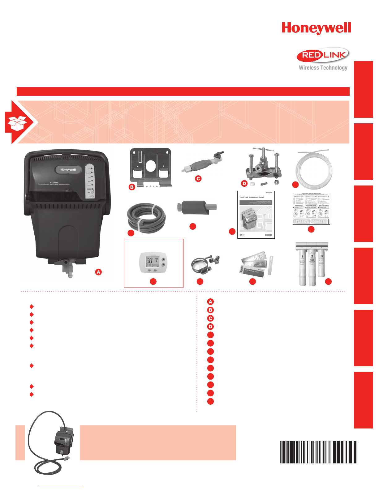
INCLUDED IN THIS HUMIDIFIER BOX
PROFESSIONAL INSTALLATION GUIDE
E
TM
STARTED
GETTING
MOUNTING PLUMBING WIRING APPENDICES
F
J3
Tools needed to install Steam Humidier
Wire cutter/stripper
1-3/4-in. diameter hole saw
1/8-in. drill bit
Standard screwdriver
18-gauge wire (up to 5 conductor)
Torx driver T-20 and T-30
Other Requirements
Steam Humidifier flushes water at or above 140°F (60°C).
Refer to local codes for proper draining practices
for hot water.
Condensate pump rating of 212°F (100°C) if used.
Drip pan with water sensor shut-off required underneath
Steam Humidifier if installed in or above finished space.
G
K L
E
F
G
H
I
J3
K
L
M
H
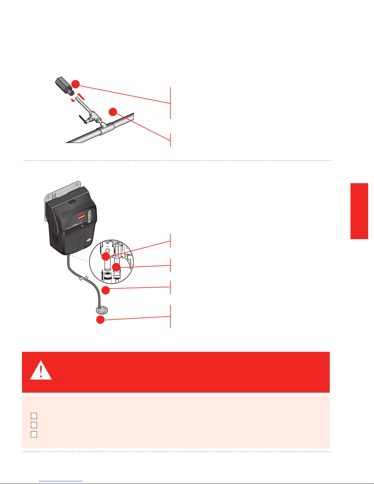
Steam Humidifier
Mounting bracket and hardware
Backflow preventer
Saddle valve
Water supply hose
Drain hose (10 feet)
Duct nozzle and gasket
Owner’s manual
Service label
HumidiPRO Digital Control
Hose clamp
Water Hardness Test Kit
RO Filter System
*RO Tank not needed with installation
I
M*
AND SERVICE
OPERATION
Remote installation requires separate purchase of the
Honeywell Remote Mounting Kit (#50024917)


Steam Humidier
Critical Installation Information ................................2
Water Quality and Hardness ...............................................2
Testing Water Quality and Interperting Results ....................2
Choosing the Filter ...............................................................2
Set the Automatic Flush Cycle Timing .................................3
Proper Sizing of a Steam Humidier Humidier ..................5
Steam Humidier Pre-Install Information .............................7
Safety Denitions and Precautions ..........................8
Safety Denitions ................................................................ 8
Safety Precautions .............................................................. 8
Setting Homeowner Expectations ............................9
Important Installation Requirements ......................10
Personal Safety .................................................................10
Mounting Location ............................................................10
Duct Nozzle ......................................................................10
Water Drainage .................................................................10
Choosing a Mounting Method .................................11
Which is right for you? .......................................................11
Duct Mounting ..........................................................12
STEP ONE: Select a Mounting Location ...........................12
STEP TWO: Connect the Duct Nozzle ...............................12
STEP THREE: Install Mounting Bracket to the Duct ..........13
STEP FOUR: Install Steam Humidier onto the
Mounting Bracket ...............................................................13
Reverse Osmosis Filter ...........................................24
Parts of the RO Filter .........................................................24
Setting up the RO Filter ....................................................25
Maintaining the RO Filter ..................................................26
Before Wiring Steam Humier .................................27
Using the DIP Switches .....................................................27
STEP ONE: Remove the Steam Humidier Cover .............27
STEP TWO: Understand the DIP Switches........................27
Deciding on the Wiring Conguration ....................29
STEP ONE: Make Power Monitoring Decision ...................29
STEP TWO: Make System Fan Regulation Decision .........31
STEP THREE: Make Add-On Air Proving Decision ...........33
Using the Terminals ...........................................................34
Routing the Wires ..............................................................34
Using the Correct Control Diagram ........................35
Mounting the Outdoor Sensor ................................38
Startup and Checkout ..............................................43
Routine Maintenance ...............................................44
Automatic Cleaning Cycle ..................................................44
STEP ONE: Initiate a Flush Cycle .....................................44
STEP TWO: Remove the Water Tank .................................46
STEP THREE: Clean the Tank ...........................................47
STEP FOUR: Replace the Water Level Sensor .................47
STARTED
GETTING
MOUNTING PLUMBING WIRING APPENDICES
Water Supply and Drain Connections ....................14
STEP ONE: Connect the Cold Water Supply .....................14
STEP TWO: Tap into a Water Line .....................................14
STEP THREE: Connect Steam Humidier to the
Cold Water Pipe .................................................................15
STEP FOUR: Connect to the Water Drain .........................15
Water Level Sensor Troubleshooting Steps ...........48
Test Setup ..........................................................................48
Test Pins ............................................................................48
Testing for Shorts ...............................................................48
Good Water Sensor ...........................................................48
Bad Water Sensor ..............................................................48
STEP FIVE: Reinstall the Tank .........................................49
Other Plumbing Options ..........................................16
For All Options Shown: ......................................................16
Connect to Steam Humidier .............................................16
Remote Installation ..................................................19
Proper Hose Installation ..........................................21
Troubleshooting .......................................................50
A: Specications ......................................................54
B: Advanced Steam Humier Wiring ....................55
C: Parts List ..............................................................66
NEED HELP? For assistance with this product please visit http://yourhome.honeywell.com
?
or call Honeywell Customer Care toll-free at 1-800-468-1502.
Read and save these instructions.
® U.S. Registered Trademark. Patents pending. Copyright © 2014 Honeywell International Inc. All rights reserved.
AND SERVICE
OPERATION
Steam Humidier System 69-2285—09
1
GETTING
A
STARTED
Critical Installation Information
Water Quality and Hardness
Proper ltration is critical for the operation of the steam humidier. Failure to address water quality will lead to
increased maintenance requirements and possible failure of the steam humidier and its components. Be sure to
complete the following procedure well in advance of installation to ensure any additional costs are documented
and understood.
It is imperative to fully understand the quality and hardness of the water that will be used on each individual steam
humidier. Water quality and water hardness can vary greatly from home to home, and even between two homes
on the same street. Water test kits are included with every steam humidier and are also available for purchase
separately (50044721-001). Proper use of these kits will help determine which ltration option is right for each
particular installation.
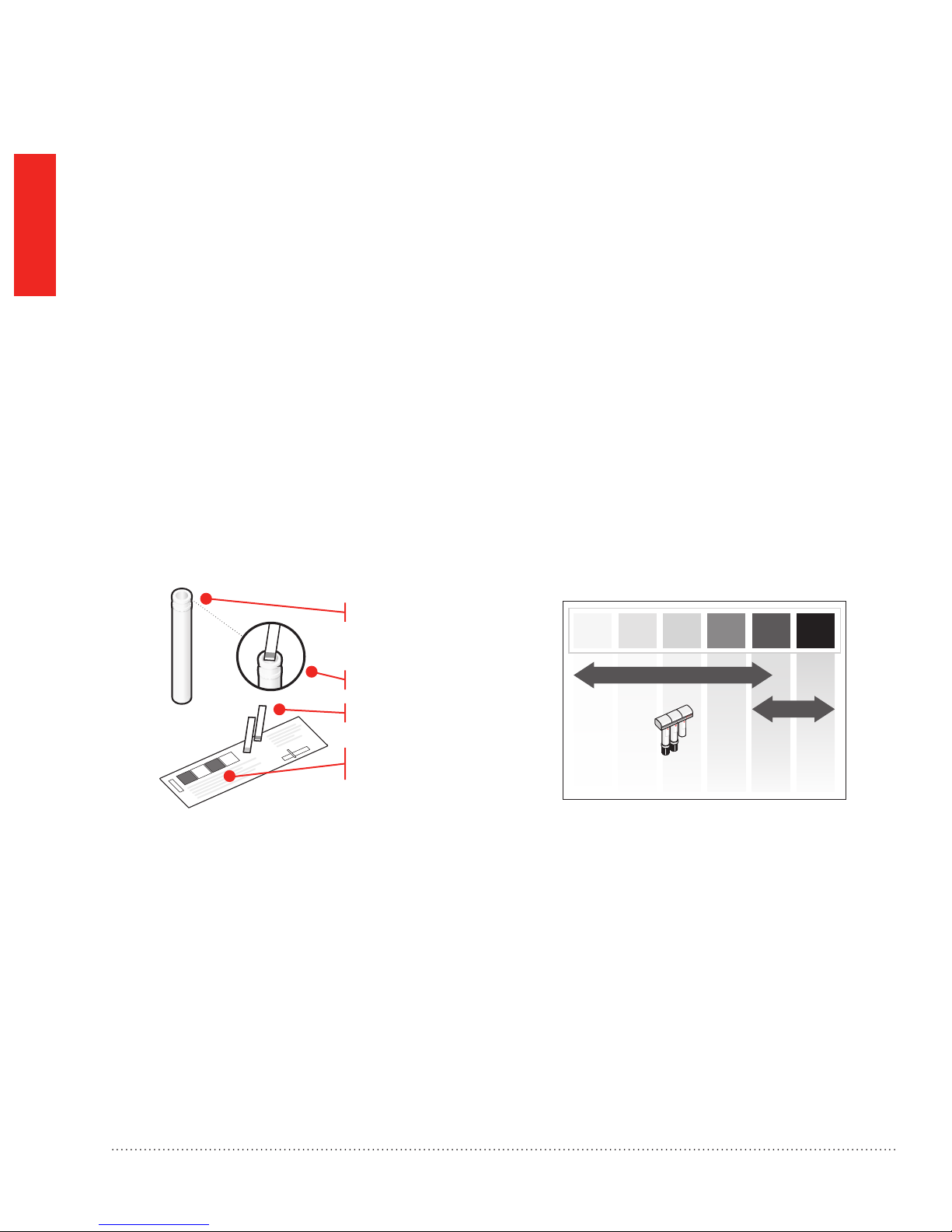
Testing Water Quality and Interpreting Results
• The color block will recommend the best water ltration method for the home.
• Water test strips will be green when new.
• Honeywell always recommends installing a reverse osmosis lter.
1
3
4
Fill the plastic tube with water directly from the
steam humidifier input water source.
Note: It is important to test the specific input to steam
humidifier, as it may differ from the faucet taps in the home.
2
Dip the colored end of one of the test strips into
the tube’s water for 3 seconds.
Remove the test strip. Do not shake the strip.
Wait 20 seconds and then match the test strip’s
color to the closest color block on the water
hardness scale.
Note: Strip color results are no longer valid after one minute.
Honeywell
Recommends
RANGE 1
RO Filter Part No.
HM600XROF1
RANGE 2
Water
Softener
MCR35268
Choosing the Filter
If the water tests in range 2 then the steam humidier will require the use of a whole-house water softener for
optimal performance. Failure to use softened water in this situation can potentially lead to drastically increased
maintenance requirements and premature failure of the steam humidier and its components. Water hardness in
this range negatively affects all facets of a home including shower heads, faucets, laundry machines (as well as
steam humidier).
2
Steam Humidier System 69-2285—09
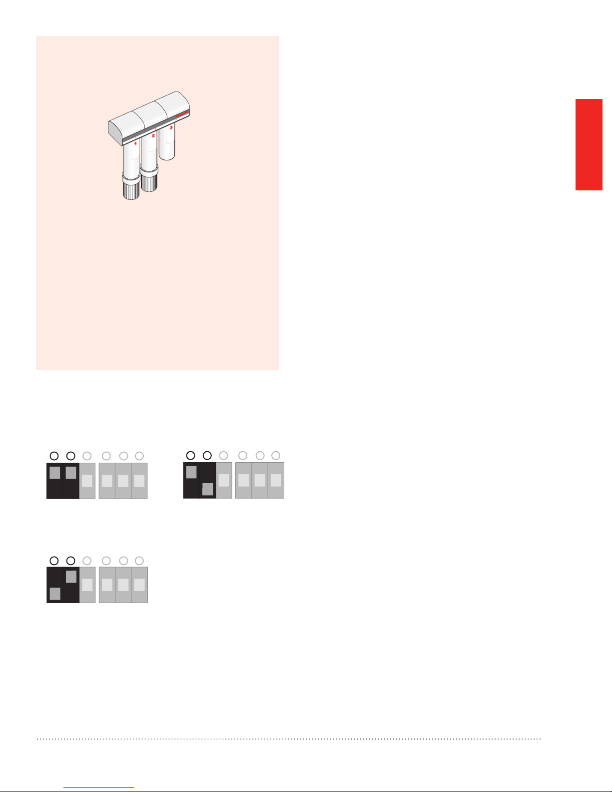
If water hardness is in range 1:
M29661
654321
On
Off
For water that is filtered through
the Honeywell RO Filter System.
(30 hour flush)
654321
65432
On
Off
1
654321
654321
On
Off
On
Of
For water that is filtered through
the Honeywell RO Filter System.
(30 hour flush)
For hard water without
a softener or filter.
(8 hour flush)
For water that is put through
a softener before
entering steam humidifier.
(20 hour flush)
On
Off
M29614A
Honeywell recommends using the RO Filtration
system
Proceed to “Water Supply and Drain
Connections” on page 14. See “Reverse
Osmosis Filter” on page 24 to install the lter.
STARTED
GETTING
Set the Automatic Flush Cycle Timing
On
Off
For water that is filtered through
the Honeywell RO Filter System.
f
For soft water without
(30 hour flush)
a softener or filter.
(12 hour flush)
On
Off
For water that is put through
654321
a softener before
entering steam humidifier.
(20 hour flush)
M29614A
654321
• Use DIP 1 and DIP 2 to congure how often steam
humidier will automatically ush the tank.
Timing for the automatic ush is based on hours of
active heating element time.
• The home’s water hardness determines how often
automatic ushing should be performed.
• The automatic ush timing can be changed any
time after installation by setting the DIP 1 and
DIP 2 positions, as shown at left. See “Automatic
Cleaning Cycle” on page 44 for a description of
the automatic ushing process.
Steam Humidier System 69-2285—09 3
GETTING
STARTED
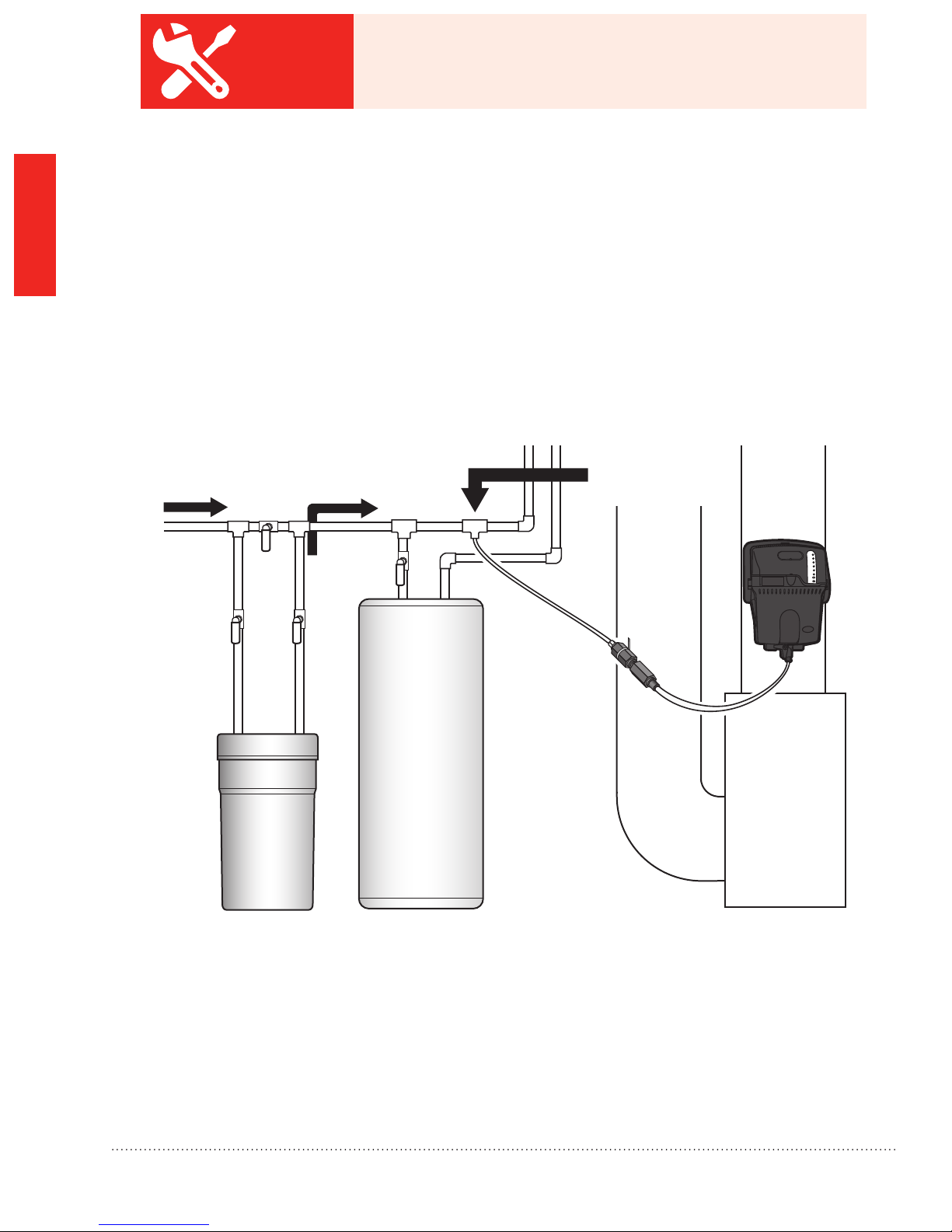
Use Steam Humidier with water that is less than 1 grain
BEST
PRACTICE
per gallon hardness. A properly functioning water softener
will accomplish this.
While the steam humidier and its available ltration options help to address the issue of water quality and
hardness, homes with extreme hard water problems should consider using a whole house water softener as
the primary ltration device. Use of a whole house water softener will help protect the humidier from excessive
maintenance requirements as well as undue wear and tear in homes with hard water.
In applications with a water softener, it is critical for the steam humidier to draw its water supply from the cold
water line after the water softener.
Note: Be sure to check all local plumbing codes before beginning installation.
Steam humidifier draws water
Hard water source
Cold softened water
from cold water line after whole
house water softener
Water
Heater
Furnace
Water
Softener
M35265
4
Steam Humidier System 69-2285—09

Proper Sizing of a Steam Humidier
The Air-Conditioning, Heating and Refrigeration Institute (AHRI) has set guidelines for determining humidication
capacity requirements. The recommendation is based on the cubic footage (volume) and type of home
construction – assuming typical conditions. It is important to realize many homes will have humidication
requirements that differ from the guidelines depending on how the circumstances differ from standard conditions.
Factors that impact the amount of humidity needed:
• Geographic Area
• Elevation
• Ventilation type
• Number of people living in the home
• Ceiling height (i.e. cubic volume)
• Window type (i.e. structure type)
• Insulation type (i.e. structure type)
• Equipment type
Converting square footage to cubic volume requires multiplying the square footage by the ceiling height (i.e. 2000
square foot space with 10 foot ceilings is 20,000 cubic feet). In general, the higher the ceilings, the smaller the
square footage space each steam humidier will cover since it must humidify the additional air volume.
STARTED
GETTING
AHRI denes structure type as follows:
• Tight construction: Well insulated with vapor retarders, tight storm doors, windows with weather stripping,
dampered replace, and using ½ air change per hour of air inltration.
• Average construction: Insulated with vapor retarders, loose storm doors and windows, dampered replace
with 1 air change per hour of air ltration.
• Loose construction: Generally built before 1930 with little or no insulation, no storm doors, no insulated
windows, no weather stripping, no vapor retarders, undampered replace, and with 1-1/2 air changes per hour
of air inltration.
It is vital to take all of these factors into account when sizing a steam humidier for a particular home. Undersizing
the humidier will not only reduce the potential to meet the a desired humidity set point, it may also lead to
extensive system fan run time or higher operating costs as the system tries to deliver to the control’s setting. While
oversizing the humidier may lead to higher amp draw, the system run time will be less, which in some situations
may be less expensive at the bottom line.
Steam Humidier System 69-2285—09 5
GETTING
STARTED
Proper Sizing of a Steam Humidier
Converting square footage to cubic volume requires multiplying the square footage by the ceiling height
(i.e. 2000 square foot space with 10 foot ceilings is 20,000 cubic feet). In general, the higher the ceilings, the
smaller the square footage space each Steam Humidier will cover since it must humidify the additional air
volume.
INCLUDE ALL SQUARE FOOTAGE OF THE HOME. FINISHED AND UNFINISHED.
Example 1: 2000 sq ft home: 8 ft ceilings = 16,000 cu ft. (2000 x 8)
Example 2: 2000 sq ft home: 10 ft ceilings = 20,000 cu ft. (2000 x 10)
Example 3: 2000 sq ft home: ½ with 8 ft ceilings, ½ with 12 ft ceilings. = 20,000 cu ft. ((1000 x 8) + (1000 x 12))
INCLUDING CEILING HEIGHT, FINISHED AND UNFINISHED SPACE WILL PROVIDE A MORE ACCURATE
SIZING FOR HUMIDIFICATION.
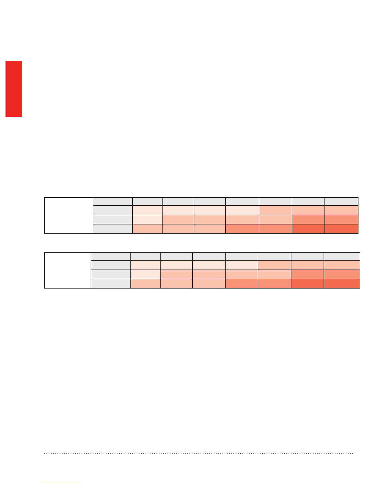
AHRI
Recommended
Humidity
(Gallons Per Day)
Recommended
Steam
Humidier
Construction Type 8,000 CU FT 12,000 CU FT 16,000 CU FT 20,000 CU FT 24,000 CU FT 28,000 CU FT 32,000 CU FT
Tight 3.3 4.3 5.4 7.5 9.6 11.7 16
Average 7.6 9.6 11.8 16 20.3 24.4 33
Loose 11.7 14.9 18.1 24.5 30.8 37.1 50
Construction Type 8,000 CU FT 12,000 CU FT 16,000 CU FT 20,000 CU FT 24,000 CU FT 28,000 CU FT 32,000 CU FT
Tight
Average
Loose
9 GPD 9 GPD 9 GPD 9 GPD 12 GPD 9 GPD X2 12 GPD X2
9 GPD 12 GPD 9 GPD X2 9 GPD X2 12 GPD X2 12 GPD X3 12 GPD X3
12 GPD 9 GPD X2 12 GPD X2 12 GPD X3 12 GPD X3 12 GPD X4 12 GPD X4
6
Steam Humidier System 69-2285—09

BEST
PRACTICE
Complete this information sheet and leave on all jobsites
In the event that a service technician needs to call in to the steam humidier support techline, the following
information is typically required for the Honeywell tech support specialist to accurately evaluate each situation.
Failure to have this information ready may result in resolution delays or a potentially incomplete diagnosis.
Honeywell recommends completing the below questionnaire and leaving a copy
behind at the home along with the Steam Humidier installation guide with every steam
humidier installation.
Honeywell steam humidier techline: 800-814-9452
Steam Humidier Pre-Install Information
Model Number of Steam Humidier Unit
Date Code (xxxx)
Water Quality Test 1 2 3 (circle one)
Water Pressure Test (psi)
Flush Cycle Setting
DIP 1 OFF ON OFF ON (circle one)
DIP 2 OFF ON ON OFF (circle one)
STARTED
GETTING
Duct Static Pressure Test (in.wc.)
(Maximum static pressure is 0.5 in.wc.)
Condensate Pump or Drain Pump Drain (circle one)
If Drain - PVC or Standard PVC Standard N/A (circle one)
Supply Voltage to Unit (V)
Monitoring Air Flow/System Power/
None
Control - Wireless or Wired Wireless Wired (circle one)
Fan Control - Steam Humidier or
Controller
Other (any additional relevant
information)
DIP 4 ON OFF (circle one)
DIP 5 ON OFF (circle one)
Steam Humidier Controller (circle one)
Steam Humidier System 69-2285—09 7

GETTING
STARTED
Safety Denitions and Precautions
Safety Denitions
These safety terms identify information you must read.
CAUTION: Indicates a hazardous situation which, if not avoided, could cause bodily injury
or property damage.
WARNING: Indicates a hazardous situation which, if not avoided, could result in death or serious injury.
Safety Precautions
Make sure you read and understand the following safety hazards before installing, using, or working
with the steam humidier:
• Do not direct the steam nozzle at people.
• Water inside tank can be very hot. Explain this to homeowner and emphasize the warning label
on steam humidier.
• Scalding danger from draining water. When the water tank drains, the water can be hot enough to cause
injury. Make sure the homeowner understands the danger of hot water and steam.
CAUTION: Voltage Hazard.
Can cause electrical shock or equipment damage.
Disconnect HVAC equipment before beginning installation.
WARNING: Electrocution, Heavy Equipment, and Water Hazard.
Can cause death, blindness, and water damage to home, and heating element failure.
CAUTION: Steam Condensation, Fire, and Freezing Water Hazard.
Can cause failure of fan or limit control or result in water damage to home.
8
Steam Humidier System 69-2285—09

Setting Homeowner Expectations
Make sure the homeowners know what to expect from their steam humidier. Discuss the following points with the
homeowners and answer any questions they have.
• Achieving Humidity Setpoint. It may take up to a week of continuous operation to achieve the humidity
setpoint. This depends on such factors as weather, size of home, furnishings in the home, and insulation.
• Plastic or Rubber Odor. At startup, it is normal to smell a slight plastic odor in the home. If the remote hose is
used, there may be a slight rubber odor. These odors will go away within a few days.
• Ideal Humidity. 35% – 45% relative humidity in typical winter weather is considered ideal by industry experts.
Homeowners can adjust to their own comfort or until there is condensation on the windows. Lower the setpoint
if condensation appears.
• Unit Not Humidifying. If steam humidier is not running but the humidity is below the setpoint, the humidity
control may have a frost protection setting. Steam humidier will not humidify while in a drain cycle mode.
STARTED
GETTING
• Setpoint Not Reached. If humidity doesn’t reach the setpoint, steam humidier may be undersized for the
home. This can be due to factors such as insulation, windows, and arid climate. Also, the outdoor temperature
may be too low to maintain the humidity level. Wait for the outdoor temperature to warm closer to 20°F (-6°C). If
the desired humidity is still not reached, then a larger capacity steam humidier may be needed.
• Home Ventilation. Excessive ventilation sends moist air outside and replaces it with dry air. This can make it
hard to maintain the humidity setpoint. If installing a ventilator, use a solution that retains moisture. An Energy
Recovery Ventilator (ERV) is recommended.
• Cleaning Required Light. If the Cleaning Required light is on, clean steam humidier using the steps found in
the “Routine Maintenance” section on page 44, or in the Homeowner’s Operating Manual. Steam Humidier
will continue to run normally while this light is on.
• Hard Water. The home’s water hardness determines how often steam humidier must be cleaned. A water
hardness test kit is provided with your steam humidier. It will help you determine the cleaning interval and
lter requirements for your steam humidier.
• Energy Consumption. There may be a slight increase in overall energy consumption when operating
any humidier. However, steam humidier will make the home feel warmer. This allows the homeowner to lower
the temperature setting on the thermostat. Every degree lower on the thermostat can save up to 3% on
heating costs.
Steam Humidier System 69-2285—09 9

GETTING
STARTED
Important Installation Requirements
Failure to comply with these requirements will result in voided warranty, improper installation, and
service callbacks.
Personal Safety
• Wear safety glasses while installing steam humidier.
• Do not cut into any air conditioning or electrical line.
• Follow professional safety standards and all local regulations.
Mounting Location
• Mount steam humidier in a level position to avoid water damage or heating element failure.
• Install steam humidier on the supply duct. Use the Remote Mounting Kit if duct mounting is not possible.
• Do not install steam humidier where the ambient temperature is lower than 34°F (1.1°C) or higher
than 104°F (40°C).
• Mounting area must be strong enough to support steam humidier’s weight when full of water (up to 15 lbs.).
• Choose a location that is well ventilated. Do not install steam humidier in completely enclosed spaces, such
as a cabinet or unventilated closet.
• Allow at least 1 foot clearance to ventilation holes in the steam humidier cover. Do not cover the holes.
Covering them can increase the temperature inside steam humidier and shorten its life.
• Do not mount directly to duct board. The remote mount nozzle attachment is allowed only with a Honeywell
duct board adapter kit. See “Appendix C: Parts List” on page 55.
• If used near a pool or spa, make sure steam humidier can not fall into the water or be splashed. Also, ensure
steam humidier is plugged into a ground fault interrupted (GFI) outlet.
10
Duct Nozzle
• Do not install the duct nozzle into a supply duct with static pressure exceeding 0.5 in. w.c.
• Do not install the duct nozzle through wooden sidewalls (e.g., oor joist).
• If the duct has exposed insulation on the interior, be sure the nozzle extends beyond the insulation. Clear away
excess insulation at the insertion point, or replace a section of insulated duct (approximately 6 in. x
6 in.) with rigid, non-insulated sheet metal.
• Allow at least 4 in. clearance between nozzle outlet and any interior duct to avoid water condensation.
• Mount steam humidier where the nozzle outlet has a minimum 24 in. of downstream open air space.
Water Drainage
• Consult local plumbing codes for drain size, material, and maximum temperature allowed.
Steam Humidier System 69-2285—09

Choosing a Mounting Method
Return
Supply
MCR29596
Supply
MCR35264
Before installing steam humidier in a home, you must decide which mounting method you want to use:
Which is right for you?
DUCT MOUNTING – if you can mount steam
humidier onto the supply duct of
the HVAC system:
The generated steam goes directly into the
supply duct.
This is the simplest type of installation, but
it requires that a suitable mounting location
can be found on the supply duct.
REMOTE MOUNTING – if a suitable
mounting location can not be found
on the supply duct:
The steam humidier can be mounted up to
20 feet away from the supply duct for
select models.
A remote hose must be installed to carry
steam from steam humidier to the supply
duct.
You will need to use a remote mounting kit
(see “Appendix C: Parts List” on page 66).
MOUNTING
This manual covers duct mounting of steam humidier. For Remote Mounting Instructions, see “Remote
Installation” on page 19 or “Document 69-2317” (included with Remote Mounting Kit).
Before proceeding:
I have decided to use: Duct Mounting Remote Mounting
Steam Humidier System 69-2285—09 11
Duct Mounting
M29598
M29599
Before beginning Duct Mounting:
I have conrmed local codes for proper draining practices for hot water
I have chosen an installation location that meets the requirements on page 10
Follow these steps to mount steam humidier directly to the supply duct of the homeowner’s HVAC equipment.
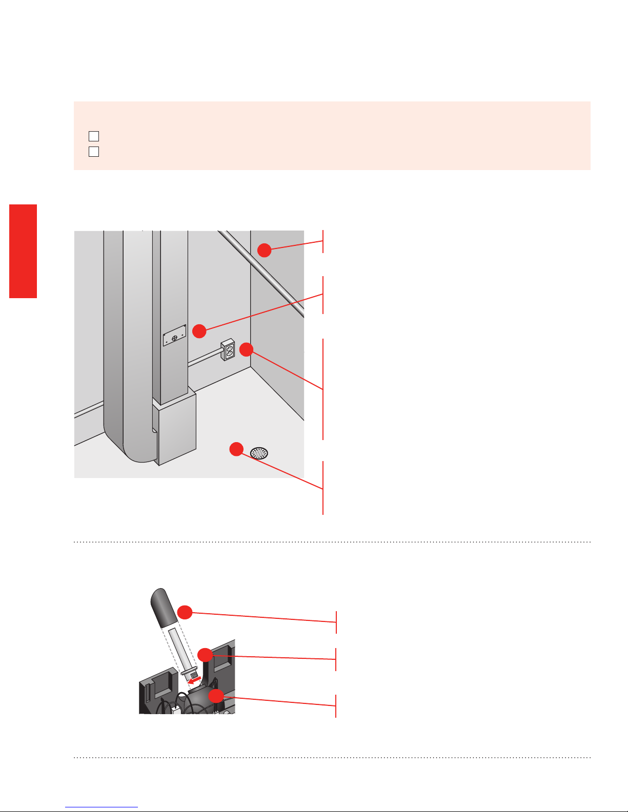
STEP ONE: Select a Mounting Location
Choose a location that has access to a cold
1
water supply pipe.
MOUNTING
STEP TWO: Connect the Duct Nozzle
Select a vertical or horizontal surface on the HVAC
supply duct, with adequate clearances, where steam
humidier can be mounted.
2
3
Make sure there is a 120 VAC electrical outlet
rated for the steam humidier being installed.
Steam Humidier Required Minimum
Circuit Capacity:
HM609 10 Amps
HM612 12 Amps
4
Ensure the location is near a drain with a high-
temperature water rating. Consult local plumbing
codes for proper drainage. If no main oor drain
is available, see “Other Plumbing Options” on page
16.
1
2
12
Slide the foam gasket over the nozzle.
Make sure the o-ring gasket is properly seated
in the groove.
3
Insert the duct nozzle into steam humidier. Twist
clockwise to ensure a tight seal.
Steam Humidier System 69-2285—09
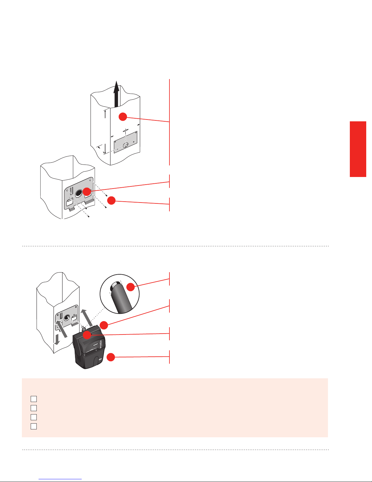
STEP THREE: Install Mounting Bracket to the Duct
M29600
Position the template on the supply duct:
• Make sure the template is level and in the desired
position on the duct.
• Ensure proper clearances from A-coil.
• Make sure the duct nozzle will have proper
clearances from duct walls.
• Minimum 4-inch clearance from nozzle outlet to any
duct wall.
• Minimum 24 inches of downstream open duct air
space. (Needed to prevent water condensation.)
Drill the 1-3/4 inch hole.
Secure the mounting bracket to the duct, using four
self-drilling sheet metal screws provided.
2
12”
(min)
4”
Flow
1
4”4”
3
MOUNTING
STEP FOUR: Install Steam Humidier onto the Mounting Bracket
Make sure the foam gasket is positioned correctly over
1
2
3
4
M29601A
Before proceeding to Plumbing:
I selected a duct mounting location
I connected the duct nozzle
I installed the mounting bracket to the duct
I installed the steam humidier onto the mounting bracket
the nozzle.
Lift steam humidier into place against the mounting
bracket. Insert the nozzle directly into the duct hole.
Check the foam gasket – it must form a tight seal in
the duct hole.
Push down to secure steam humidier to the bracket
arms.
Steam Humidier System 69-2285—09 13
MCR35266
BEST
PRACTICE
Use a manual shutoff valve when tapping into a water line.
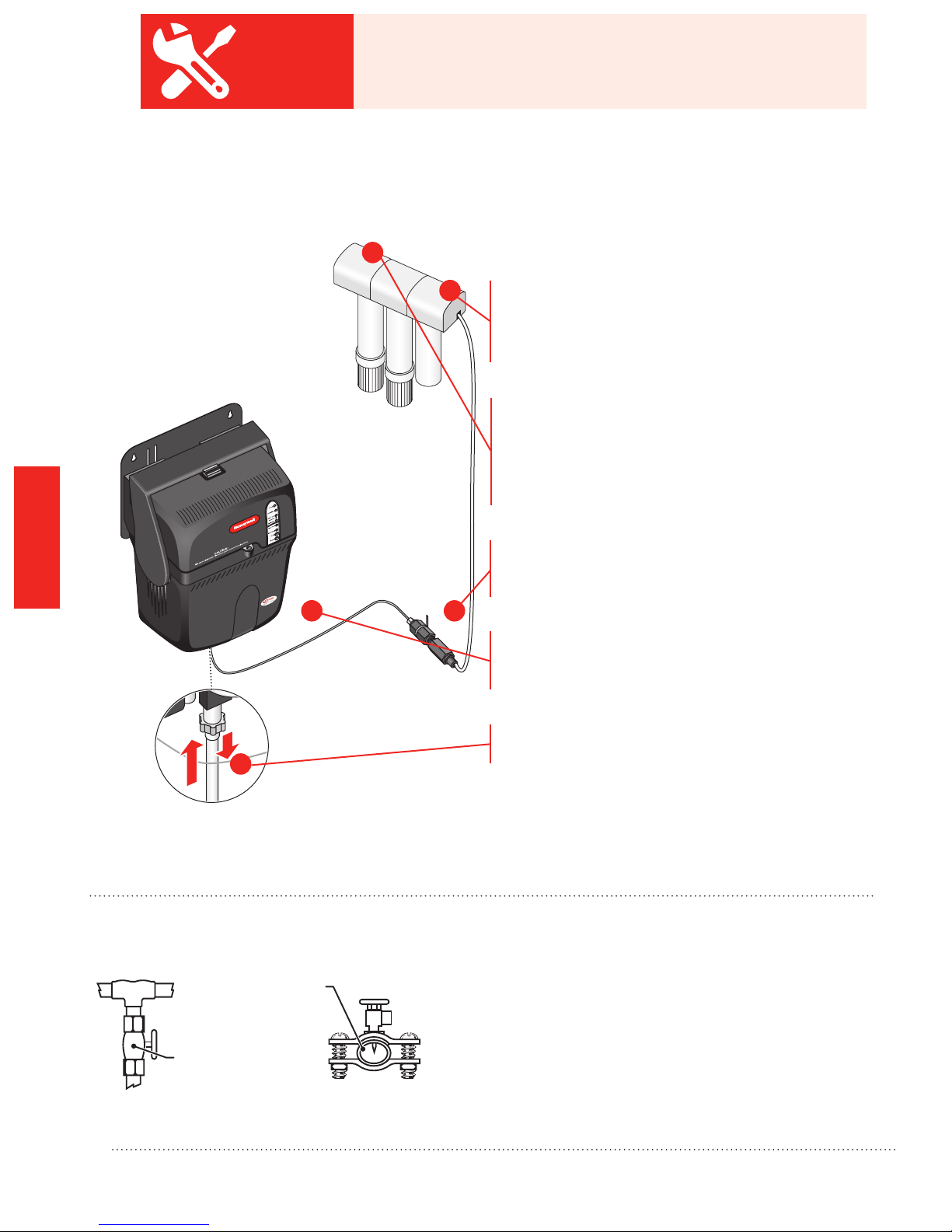
Water Supply and Drain Connections
STEP ONE: Connect the Cold Water Supply
2
Do not use hot water supply. Cold water is required
to cool boiling water to safe draining temperatures.
PLUMBING
1
Insert one end of the water line into the water lter
or reverse osmosis kit. Use the 1/4-inch plastic
water line provided or a 1/4-inch copper water line.
Apply a modest pull to ensure a tight t.
Use clamps or ties to secure the water lter in a
location that allows for removing and replacing it in
the future. Honeywell recommends changing the
water lter or RO canisters 1 & 2 annually, or as
needed based on water conditions.
Install the provided backow preventer, as required
by code. See “Reverse Osmosis Filter” if using the
Reverse Osmosis Filter.
4
3
Cut the water line so it is long enough to reach
from the water lter to the supply tting on the
bottom of the steam humidier.
Insert the water line into the steam humidier
5
supply tting.
STEP TWO: Tap into a Water Line
Water Supply
Line
Manual Shutoff
Valve
T-fitting
14
Note: Failure to check for a tight t with plastic water line
could result in the line coming loose in the future. Apply
modest pull to ensure water line is properly seated and
secure.
• Consult local codes for proper plumbing.
• Use the saddle valve provided or a T-tting and
manual shutoff valve to tap into a cold water
line.
• Refer to the literature included with the valve
you chose and the local plumbing codes. Use
proper technique for the valve.
Saddle Valve
M29605
Steam Humidier System 69-2285—09
STEP THREE: Connect Steam Humidier to the Cold Water Pipe
MCR32901
1
Connect one end of the remaining length of water
line to the backow preventer. Apply a modest pull
2
to ensure a tight t. See “Reverse Osmosis Filter” on
page 24 if using the Reverse Osmosis Filter.
Connect the other end of this line to the saddle valve
or T-tting and manual shutoff valve.
STEP FOUR: Connect to the Water Drain
• Consult and follow local plumbing codes for drain
pipe size and maximum temperature requirement.
• The ideal installation is directly to the main oor
drain using the rubber hose provided.
• If direct oor drain access is not available, see
“Other Plumbing Options” on page 16.
Connect the 1/2-inch drain hose provided to the drain
tting on the bottom of the steam humidier.
PLUMBING
1
2
3
MCR29607
4
CAUTION: Scalding Hazard.
During operation, hot water may exit drain and can cause burns from scalding.
Make sure the hose is securely connected to the drain.
Before proceeding to Wiring:
I have conrmed minimum required circuit capacity
I have connected the water supply using cold water
I have installed the drain connection
Use the hose clamp provided to secure the drain hose
to the barbed tting.
Route the drain hose to the oor drain. The hose must
have a continuous downward slope.
Direct the hose outlet into the oor drain. Secure
the hose to reduce the risk of hot water pooling
or splashing.
Note: Some building codes require an air gap between
discharge hose and oor drain.
Steam Humidier System 69-2285—09 15
Other Plumbing Options
1/2 IN. BARB X 3/4 IN. MNPT
3/8-IN. TUBING
M28713A
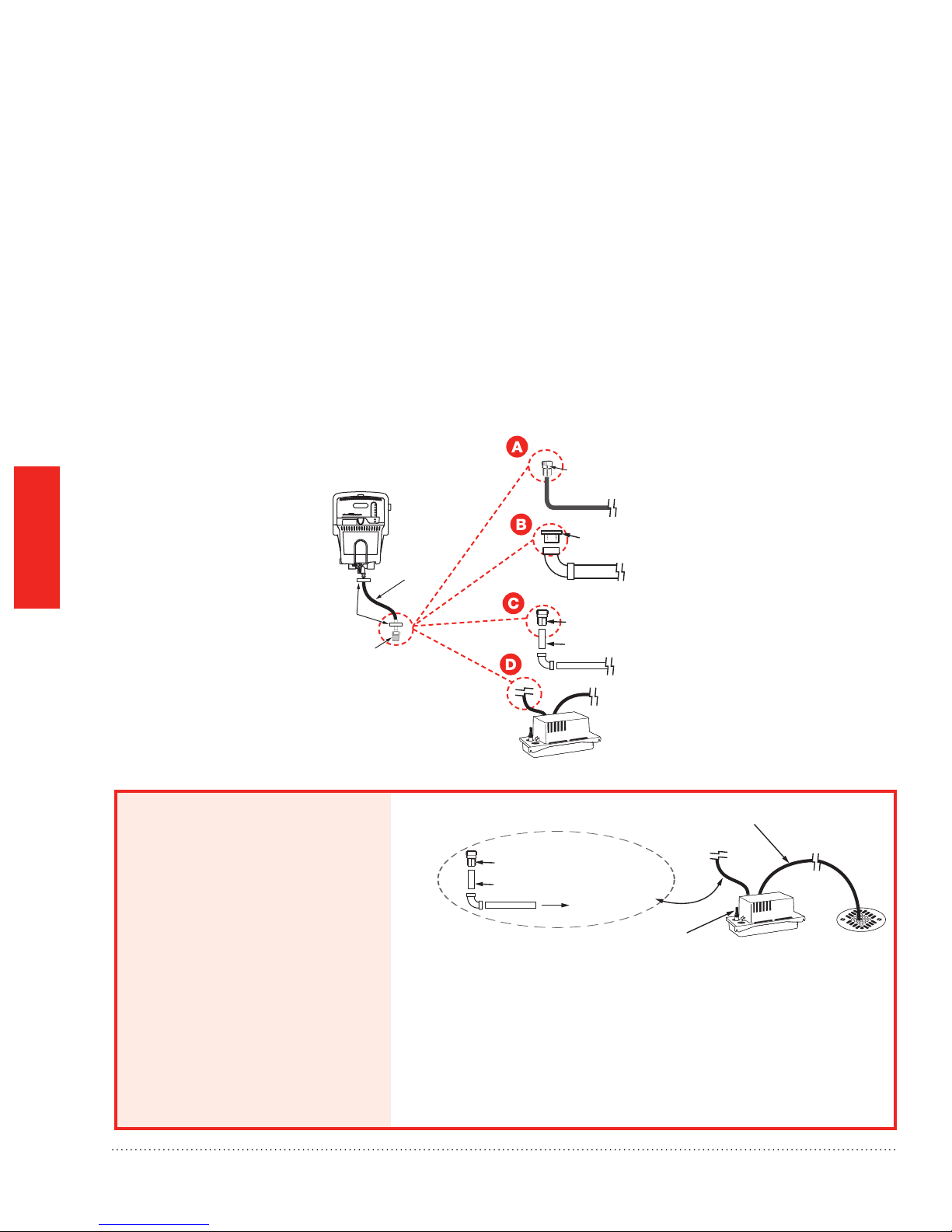
The following diagrams are for applications where standard draining to a oor drain is not available.Choose the
plumbing option that suits your installation. Use A, B, C, or D based on type of pipe or condensate pump. Consult
and follow local plumbing codes in addition to these instructions.
For All Options Shown:
PLUMBING
• Support rubber hose every 6 in.
• PVC must be schedule 40 or higher rating.
Connect to Steam Humidifier
Common to all plumbing options.
SEAL ALL CONNECTIONS FROM
SOLENOID VALVE TO DRAIN STACK
FLEXIBLE
HOSE
HOSE
CLAMPS
212°F RATED PUMP
HOSE FROM
STEAM
HUMIDIFIER
• All plastic pipe joints are welded.
• Drain into a P-trap that will remain wetted at all
times.
3/4 IN. FNPT X SWEAT
3/4 IN. COPPER PIPE
3/4 IN. FNPT X
1-1/2 IN. PVC
1-1/2 IN. (MINIMUM) PVC PIPE
3/4 IN. FNPT X 3/4 IN. CPVC
3/4 IN. CPVC PIPE
3/8-IN. TUBING
RATED AT 212°F
MCR28678
Option 1: Plumbing
to drain with
condensate pump.
16
RATED AT 212°F
ALTERNATIVE
3/4 IN. FNPT X 3/4 IN. CPVC
3/4 IN. CPVC PIPE
TO PUMP
HOSE CLAMPS AT
ALL CONNECTIONS
HOSE FROM
STEAM HUMIDIFIER
• Use Hartell A3X-115 condensate pump or equivalent
(212°F temperature rating, > 1 GPM pump flow rate).
• Pump must be powered when Steam Humidifier is operating.
• Use a pump with a built-in overflow sensor or install the pump
in a drip pan with wet switch wired to turn off Steam Humidifier.
Steam Humidier System 69-2285—09

M28679
3/4 IN. FNPT X 1-1/2 IN. PVC
3/8 IN. BARB X 3/4 IN. MNPT
SIZE TO FIT PUMP OUTPUT
Option 2: Plumbing to a dedicated trap.
1-1/2 IN. (MINIMUM)
PVC PIPE
STAINLESS STEEL
SLOTTED BAND
COUPLING SIZED TO
FIT PIPE (COPPER,
PVC, CPVC
SIZE TO FIT PUMP OUTPUT
3/4 IN. MNPT X SWEAT
3/4 IN. FNPT X 1-1/2 IN. PVC
1-1/2 IN. (MINIMUM) PVC PIPE
1-1/2 IN. PVC
3/4 IN. MNPT X 3/4 IN. CPVC
3/4 IN. FNPT X 1-1/2 IN. PVC
HOSE CLAMP
1-1/2 IN. MINIMUM TRAP
(OR SIZE PER LOCAL CODE)
VENTED PER
LOCAL CODE
ALL PLASTIC PIPE
JOINTS ARE WELDED
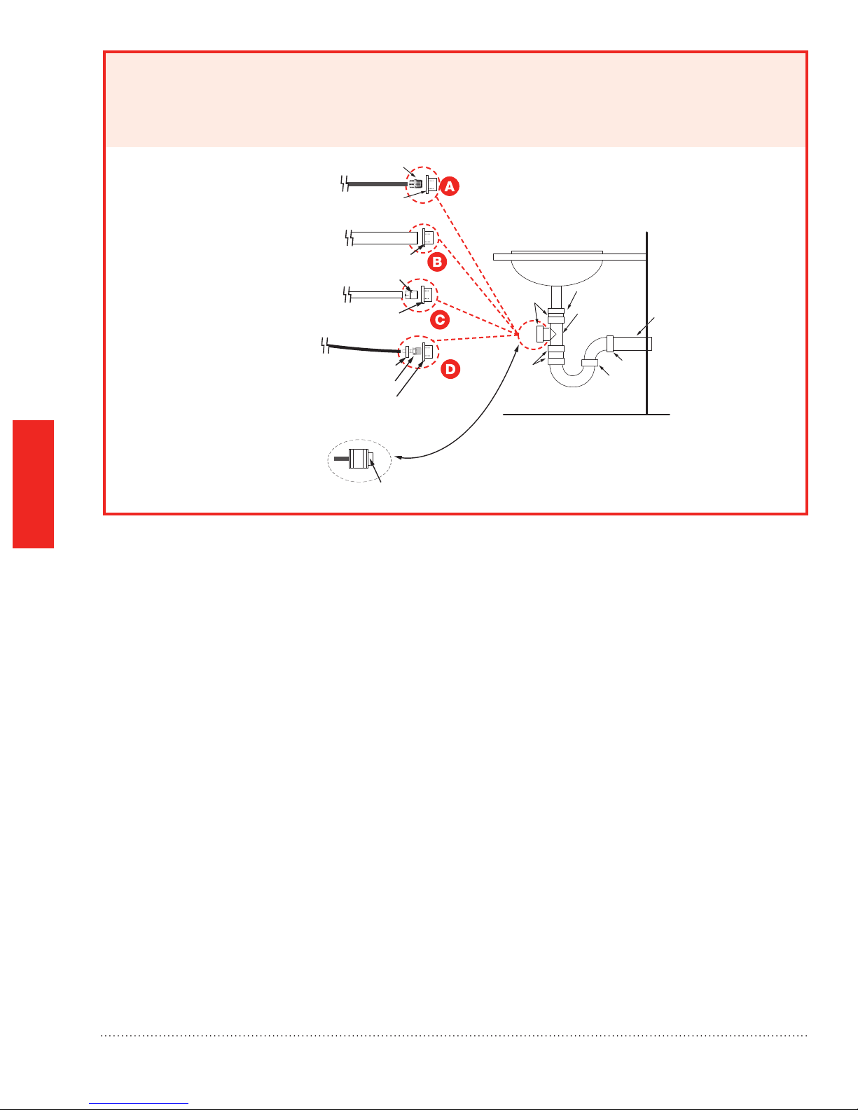
Option 3: Plumbing to sink with a dedicated trap.
PLUMBING
3/4 IN. MNPT X SWEAT
3/4 IN. FNPT X 1-1/2 IN. PVC
1-1/2 IN. PVC
3/4 IN. MNPT X 3/4 IN. CPVC
3/4 IN. FNPT X 1-1/2 IN. PVC
HOSE CLAMP
3/8 IN. BARB X 3/4 IN. MNPT
3/4 IN. FNPT X 1-1/2 IN. PVC
)
WELD
ALTERNATIVE
THIS CONFIGURATION ALLOWS FOR
REMOVAL OF THE TRAP
1-1/2 IN. PVC
ALL CONNECTIONS FROM
SOLENOID VALVE TO
DRAIN TRAP ARE SEALED
SINK
WELD
WELD
THREADS
ALL PLASTIC PIPE UNDER
SINK 1-1/2 IN. MINIMUM PVC
COUPLING
WELD
WYE
THREADS
M28681
Steam Humidier System 69-2285—09 17
3/4 IN. MNPT X SWEAT
.
STAINLESS STEEL
SLOTTED BAND
COUPLING SIZED TO
FIT PIPE (COPPER,
PVC, CPVC)
Option 4: Plumbing to sink trap.
PLUMBING
3/4 IN. FNPT X 1-1/2 IN. PVC
1-1/2 IN. (MINIMUM)
PVC PIPE
1-1/2 IN. PVC
3/4 IN. MNPT X 3/4 IN. CPVC
3/4 IN. FNPT X 1-1/2 IN. PVC
HOSE CLAMP
3/8 IN. BARB X 3/4 IN. MNPT
3/4 IN. FNPT X 1-1/2 IN. PVC
SIZE TO FIT PUMP OUTPUT
1-1/2 IN. PVC
ALL CONNECTIONS FROM
SOLENOID VALVE TO
DRAIN TRAP ARE SEALED
SINK
WELD
WELD
ALTERNATIVE
THIS CONFIGURATION ALLOWS FOR
REMOVAL OF THE TRAP
COUPLING
1-1/2 IN.
PVC TEE
WELD
THREADS
1-1/2 IN
PVC
M28680
18
Steam Humidier System 69-2285—09
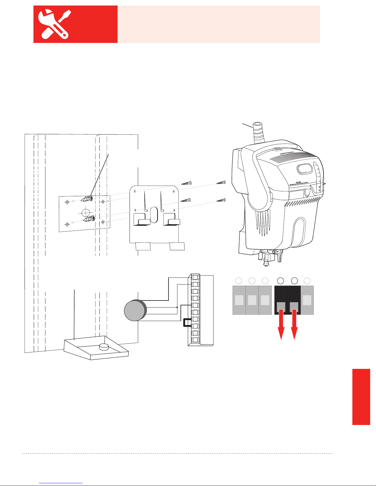
If humidier is in nished space, always install a drip pan
MCR28708
BEST
PRACTICE
with wet switch. Honeywell recommends Diversitech WS-1
(wiring shown here).
Remote Installation
Use remote installation when no suitable duct mounting location can be found on the homeowner’s
HVAC system. For detailed instructions on remote installation, see the steam humidier Remote Mount Kit
Installation Instructions (69-2317).
Always pitch the remote Adapter Nozzle upwards
Use provided anchors if mounting
to drywall or plaster
If humidifier is in finished space, always
install a drip pan with wet switch.
Honeywell recommends Diversitech WS-1
(wiring shown here.)
RED
BLACK
GREEN
ORANGE
STEAM
HUMIDIFIER
TERMINAL
24V
24V
HUM
HUM
C
GT
R
RT
GF
EXT
On
Off
1
65432
APPENDICES
Steam Humidier System 69-2285—09
19

BEST
Cut a slit in the insulation half way
around the hose
Minimum
pitch
per
Nozzle
PRACTICE
.
Always inspect the hose installation after at least 1 hour of
steam production to conrm that there are no sags in the
hose or leaks at the connection points.
at upward pitch.
upward
of 2 inches
foot.
Avoid sharp kinks and
prevent bends.
Minimum of
6 inches
of straight
vertical rise.
12 inches
Do not cut into the
rubber steam hose.
3 inches minimum clearance from nozzle
outlet to duct.
1-3/4 inch hole
Clamp
On straight runs, use perforated angle
iron. Otherwise, secure hose every 12 inches
using provided hooks.
Clearance hole for hose and insulation.
Seal off unconditioned space with
Clamp
grommet (not provided) or caulk.
Always install nozzle so the
outlet is pointed up.
Do not route the steam
hose through the hole
in the mounting plate.
On straight runs, use
perforated angle iron.
Otherwise, support
hose every 12 inches
using provided hooks.
24 inches open air downstream.
If hose slopes downhill…
Downward slope can not be more than
3 feet below humidifier steam outlet.
Provide a 212°F rated Te e at the
lowest point. Do not use plastic Te e.
Minimum 6 inches
Minimum 2 inches
Insert the hose clamp into
the slit and hook it onto the
rubber hose.
Hose clamps at
every connection.
Minimum upward
pitch of 2 inches
per foot.
Nozzle at
Clamps
upward pitch.
APPENDICES
20
Always consult and follow local
plumbing codes for drain pipe
size and maximum temperature
requirement.
Water in elbow.
Note: Some building codes require
an air gap between discharge hose
and floor drain.
M29636
Steam Humidier System 69-2285—09
 Loading...