

ST 800/ST 700 SmartLine Pressure Transmitter
Quick Start Installation Guide
34-ST-25-36, Revision 10, June 2020
Table of Contents
Figure 12: Jumper Location HART/DE ....................................................................... 5
Figure 1:Mounting Brackets
This document provides descriptions and
procedures for the Quick Installation of
Honeywell’s family of SmartLine Pressure
Transmitters.
The SmartLine Pressure Transmitter is
available in a variety of models for
measuring Differential Pressure (DP),
Gauge Pressure (GP), and Absolute
Pressure (AP). For full details refer to the
manuals listed below for protocols, human
interface (HMI), Operation, Installation,
Configuration, Calibration, Maintenance,
Parts, Safety and Approvals etc. including
options.
Documentation
To access complete documentation, including language variants, scan
the QR code below using your smart phone/device or QR code scanner.
Go to the APP store for your free Smartphone QR scanner
Or you can follow the URL to access the online SmartLine HUB page.
The HUB page will contain direct links to open SmartLine product
documentation.
URL QR Code
https://hwll.co/SmartLineHUB
Copyrights, Notices and
Trademarks
Copyright 2020 by Honeywell
Revision 10 – June 2020
Trademarks
SFC, SmartLine, ST 800 and ST
700 are U.S. registered
trademarks of Honeywell Inc.
HART® and FOUNDATION™ are
trademarks of the FieldComm
Group™
Installation ................................................................................................................... 1
Mounting the Transmitter ............................................................................................ 1
Bracket Mounting ........................................................................................................ 1
Optional Mounting Bracket ......................................................................................... 1
Existing Mounting Bracket.......................................................................................... 2
Rotating Transmitter Housing .................................................................................... 2
Leveling Transmitters with Small Absolute or Differential Pressure Spans .......... 2
Flange Mounting ......................................................................................................... 2
Flush Mounting ............................................................................................................ 3
Remote Seal Mounting ............................................................................................... 3
Conduit Entry Plugs and Adapters .............................................................................. 3
Wiring Connections and Power Up ............................................................................. 4
Wiring Variations ......................................................................................................... 4
Explosion-Proof Conduit Seal ..................................................................................... 4
Tri m the Transmitter .................................................................................................... 4
Procedure to Trim the Transmitter ............................................................................ 4
Set the Jumpers For HART/DE ................................................................................... 5
Setting Failsafe Direction and Write Protect Jumpers ............................................. 5
Write Protect Jumper on Foundation Fieldbus (FF) .................................................... 5
Configuration Guide .................................................................................................... 5
PRODUCT CERTIFICATIONS ................................................................................... 6
Hazardous Locations Certifications............................................................................. 7
Control Drawing .......................................................................................................... 9
Table 1 - Conduit Entry Plugs ..................................................................................... 3
Table 2 - Conduit Adapters ......................................................................................... 3
Table 3 - Jumper Settings ........................................................................................... 5
Table 4 - Fieldbus Write Protect.................................................................................. 5
Figure 1:Mounting Brackets ........................................................................................ 1
Figure 2: Angle Mounting Bracket ............................................................................... 1
Figure 3: LGP and LAP models .................................................................................. 2
Figure 4: Rotating Transmitter Housing ...................................................................... 2
Figure 5: Using level to mount transmitter .................................................................. 2
Figure 6: Flange mounting .......................................................................................... 2
Figure 7: Flush Mounting ............................................................................................ 3
Figure 8: Remote Seal mounting ................................................................................ 3
Figure 9: Electronic Housing Conduit Entries ............................................................. 3
Figure 10: Two-wire power/current loop ...................................................................... 4
Figure 11: Terminal Block and Grounding Screw location .......................................... 4
Tables
Figures
Installation
Evaluate the site selected for the Transmitter installation with respect to the process
system design specifications and Honeywell’s published performance characteristics
for your particular model.
Temperature extremes can affect display quality. The display can become unreadable
at temperature extremes; however, this is only a temporary condition. The display will
again be readable when temperatures return to within operable limits.
Mounting the Transmitter
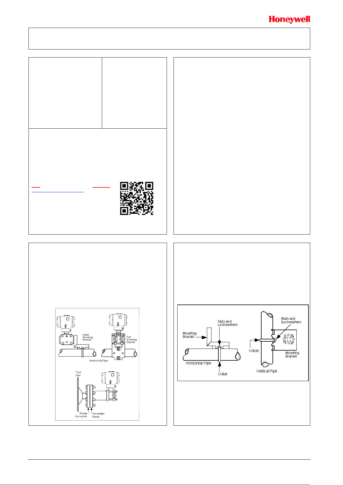
Transmitter models, except flush mounts and those with integral flanges, can be
attached to a two-inch (50 millimeter) vertical or horizontal pipe using Honeywell’s
optional angle or flat mounting bracket; alternately you can use your own bracket.
Flush-mount models are attached directly to a process pipe or tank by a one-inch weld
nipple. Models with integral flanges are supported by the flange connection.
Typical Bracket mounted and Flange Mounted Installations
Bracket Mounting
• Optional mounting bracket, see Figure 2
• Existing mounting bracket, see Figure 3
• Rotate the transmitter housing, see Figure 4
Level a transmitter with small absolute or differential pressure spans, see Figure 5
Optional Mounting Bracket
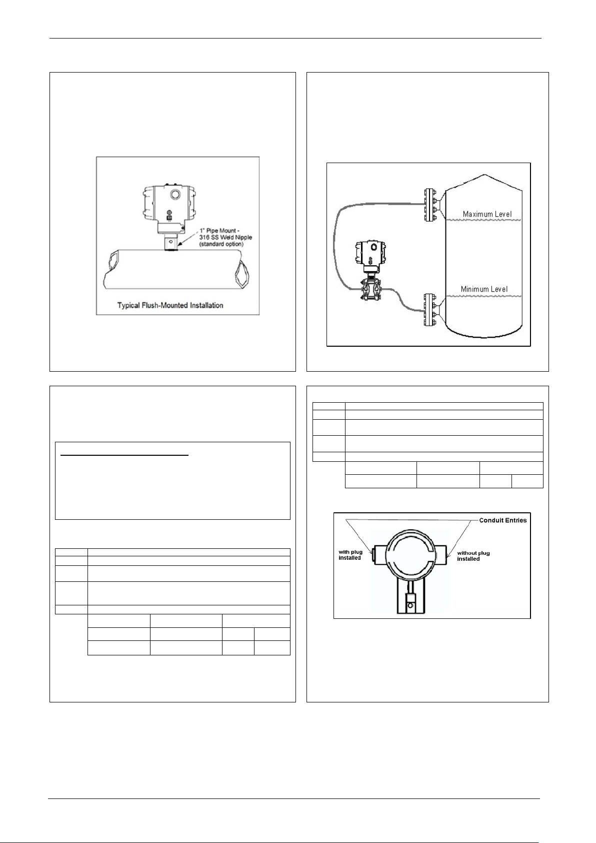
Position the bracket on a 2-inch (50.8mm) and install “U” bolt around pipe and
through holes in bracket. Secure with nuts and lock washers provided.
Figure 2 Example - Angle mounting bracket secured to horizontal or vertical pipe.
Figure 2: Angle Mounting Bracket
Quick Start Installation Guide 1

Existing Mounting Bracket
Align appropriate mounting holes in transmitter with holes in bracket and secure with
bolts and washers provided.
Note: If the meter body is hexagonal, you must use the additional bracket supplied. If
meter body is round, discard the bracket.
Example – LGP model transmitter mounted to optional angle mounting bracket.
If Transmitter is….
DP, Dual Head GP, Dual Head AP
and DP Remote Seals.
In-line GP and AP (LGP model) or
GP/AP Remote Seal
Then….
Use alternate mounting holes in end of
heads.
Use smaller “U” bolt provided to attach
meter body to bracket. See Figure 3.
Rotating Transmitter Housing
Loosen set screw on outside neck of transmitter one full turn. Rotate Transmitter housing
in maximum of 180 degree increment in left or right direction from center to position you
require and tighten set screw (1.46 to 1.68Nm/13 to 15lb-in).
Figure 4 Example – Rotating Transmitter Housing.
Figure 4: Rotating Transmitter Housing
Figure 3: LGP and LAP models
Leveling Transmitters with Small Absolute or Differential Pressure Spans
Mounting position of these transmitters is critical due to the smaller transmitter spans.
To minimize these positional effects on calibration (zero shift), take the appropriate
mounting precautions that follow for the given transmitter model.
See Figure 5 for suggestions on how to level the transmitter using a spirit balance.
To perform a Zero Trim after leveling, refer to Trim the Transmitter on page 4.
Figure 5: Using level to mount transmitter
For model STA840, STA822, STA740 or STA722 transmitters, you must ensure that
the transmitter is vertical when mounting it. You do this by leveling the transmitter
side-to-side and front-to-back.
Mount transmitter vertically to assure best accuracy. Position the spirit balance on the
pressure connection surface of AP body.
Flange Mounting
To mount a flange mounted transmitter model, bolt the transmitter’s flange to the flange
pipe on the wall of the tank.
On insulated tanks, remove enough insulation to accommodate the flange extension.
It is the End User’s responsibility to provide a flange gasket and mounting hardware that
are suitable for the transmitter’s service condition.
To prevent degradation of performance in Flush-Mounted Flanged Transm itters, exercis e
care to ensure that the internal diameter of the flange gasket does not obstruct the
sensing diaphragm.
To prevent degradation of performance in Extended Mount Flanged Transmitters, ensure
that there is sufficient clearance in front of the sensing diaphragm body.
Figure 6: Flange mounting
Quick Start Installation Guide 2
Step
Action
1
Remove the protective plastic cap from the threaded conduit entry.
2
To ensure the environmental ingress protection rating on tapered
Thread the appropriate size conduit plug (M20 or ½” NPT) into the
4
Tighten adapters according to the following table.
½” NPT Conduit
Entry
Step
Action
1
Remove the protective plastic cap from the threaded conduit entry.
2
To ensure the environmental ingress rating on tapered threads (NPT),
Thread the appropriate size adapter (M20 or ½ NPT) into the conduit
entry opening
4
Tighten adapters according to the following table.
Flush Mounting
To mount a flush mounted transmitter model, cut a hole for a 1-inch standard pipe in the
tank or pipe where the transmitter is to be mounted. See Figure 7.
Weld the 1-inch mounting sleeve to the wall of the tank or to the hole cut on the pipe.
Insert the meter body of the transmitter into the mounting sleeve and secure with the
locking bolt. Tighten the bolt to a torque of 6.4Nm ±0.30Nm [4.7ft.-lbs. ±0.2ft.-lbs.]
Once the transmitter is mounted, the transmitter housing can be rotated to the desired
position. See Figure 7.
Figure 7: Flush Mounting
Remote Seal Mounting
Mount the transmitter at a remote distance determined by length of capillary tubing.
Note: The combination of tank vacuum and high pressure capillary head effect should
not exceed 9psi (300mm Hg) absolute.
On insulated tanks, remove enough insulation to accommodate the mounting sleeve.
Figure 8 Example – Typical Remote Seal Transmitter installation.
Note: For Sanitary 3-A installations, only mount the transmitter outside of the NonProduct Contact area where incidental contact with the process material is unlikely,
use a minimum capillary length of 1.5m (5ft.)
Figure 8: Remote Seal mounting
Conduit Entry Plugs and Adapters
Procedures
It is the User/Installer’s responsibility to install the Transmitters in accordance with
national and local code requirements. Conduit entry plugs and adapters shall be
suitable for the environment, shall be certified for the hazardous location when required
and acceptable to the authority having jurisdiction for the plant.
CONDUIT ENTRY PRECAUTIONARY NOTICE
THE CONDUIT/CABLE GLAND ENTRIES OF THIS PRODUCT ARE SUPPLIED
WITH PLASTIC DUST CAPS WHICH ARE NOT TO BE USED IN SERVICE.
IT IS THE USER’S RESPONSIBILITY TO REPLACE THE DUST CAPS WITH
CABLE GLANDS, ADAPTORS AND/OR BLANKING PLUGS WHICH ARE
SUITABLE FOR THE ENVIRONMENT INTO WHICH THIS PRODUCT WILL BE
INSTALLED. THIS INCLUDES ENSURING COMPLIANCE WITH HAZARDOUS
LOCATION REQUIREMENTS AND REQUIREMENTS OF OTHER GOVERNING
AUTHORITIES AS APPLICABLE.
Use the following procedures for installation:
Table 1 - Conduit Entry Plugs
a non-hardening thread sealant may be used.
3
Table 2 - Conduit Adapters
Description Tool Torque
½ to ¾ NPT Adapter 1 ¼” Wrench 32Nm 24Lb-ft
threads (NPT), a non-hardening thread sealant may be used.
3
conduit entry opening. Do not install conduit entry plugs in conduit entry
openings if adapters or reducers will be used.
Description Tool Torque
M20 Conduit Entry 10mm Hex Wrench 32Nm 24Lb-ft
10mm Hex Wrench 32Nm 24Lb-ft
Note. No plugs come installed in the housings. All housings come with temporary
plastic dust protectors (red) installed and are not certified for use in any installation
Figure 9: Electronic Housing Conduit Entries
Quick Start Installation Guide 3

Wiring Connections and Power Up
The above procedures are used to connect power to a Transmitter. For loop wiring and
Step
Action
2
Remove the end cap cover from the terminal block end of the Electronics
3
4
5
6
Step
Action
1
Attach the transmitter to the mounting bracket but do not
completely tighten the mounting bolts
2
Connect a tube between the input connections in the high
3
Connect 24Vdc power to the transmitter. For HART/DE connect
5
or near zero, and then completely tighten the mounting bolts.
6
The Local Display or applicable communicator can be used to
tightened.
7
Summary
The transmitter is designed to operate in a two-wire power/current loop with loop resistance
and power supply voltage within the operating range shown in Figure 10.
Loop wiring is connected to the transmitter by simply attaching the positive (+) and
negative (–) loop wires to the positive (+) and negative (–) SIGNAL screw terminals on the
terminal block in the transmitter’s electronics housing shown in Figure 11.
Each transmitter includes an internal terminal to connect it to earth ground. Also, a ground
terminal can be optionally added to the outside of the electronics housing. While it is not
necessary to ground the transmitter for proper operation, doing so tends to minimize the
possible effects of noise on the output signal and affords protect ion aga inst lightn ing and
static discharge.
An optional lightning terminal block can be installed in place of the non-lightning terminal
block for Transmitters that will be installed in an area that is highly susceptible to lightning
strikes.
Figure 10: Two-wire power/current loop
Explosion-Proof Conduit Seal
When installed as explosion proof in a Division 1 Hazardous Location, keep covers
tight while the Transmitter is energized. Disconnect power to the Transmitter in the
non-hazardous area prior to removing end caps for service.
When installed as non-incendive equipment in a Division 2 hazardous location,
disconnect power to the Transmitter in the non-hazardous area, or determine that the
location is non-hazardous before disconnecting or connecting the Transmitter wires.
Transmitters installed in f o r p r ot ect ion explosion proof in Class I, Division 1 do not need
an explosion proof seal in ac c o r dance with ANSI/ NF PA 70, the US National Elect rical
Code. A LISTED explosion proof seal t o be installed in the conduit, wit h in 18 in ch es
(457.2mm) of the Transmitt er w h en 3/4" co n d u it is u sed .
Crouse-Hinds type EYS/EYD or EYSX/EYDX are examples of LISTED explosion proof
seals that meet this requirement. Transmitters installed as explosion proof in Class I,
Division 1, Group B, C or D hazardous (classified) locations do not require that
explosion proof seal be installed in the conduit.
1
See Figure 11, above, for parts locations.
Housing
Feed loop power leads through one end of the conduit entrances on
either side of the Electronics Housing. The Transmitter accepts up to 16
AWG wire.
Plug the unused conduit entrance as specified in Table 1.
Connect the positive loop power lead to the positive (+) terminal and the
negative loop power lead to the negative (-) terminal. Note that the
Transmitter is not polarity-sensitive.
Replace the end cap, and secure it in place using a 1.5mm hex wrench.
Figure 11: Terminal Block and Grounding Screw location
Note: The right hand terminal is for loop test and is not applicable for the Fieldbus
option.
Wiring Variations
external wiring, detailed drawings are provided for Transmitter installation in
non-intrinsically safe areas and for intrinsically safe loops in hazardous area locations.
This procedure shows the steps for connecting power to the transmitter.
Wiring must comply with local codes, regulations and ordinances. Grounding
may be required to meet various approval body certification, for example CE
conformity. Refer to the SmartLine Transmitter User’s Manual, Documents # 34-
ST-25-35 (ST 800) or 34-ST-25-44 (ST 700) for details.
Trim the Transmitter
Procedure to Trim the Transmitter
For a transmitter with a small differential pressure span, you must ensure that the
transmitter is vertical when mounting it. You do this by leveling the transmitter side-to-
side and front-to-back. See Figure 5 for suggestions on how to level the transmitter
using a spirit balance. You must also zero the transmitter by following the steps in
this table.
pressure (HP) and low pressure (LP) heads to eliminate the
effects of any surrounding air currents.
a digital voltmeter to monitor the PV output.
4 Use applicable communicator to establish communications with
the transmitter. For DE transmitter use SFC, SCT, or MCT. For
Hart, use MCT or other Hart Communicator with applicable
Honeywell DD's. For Fieldbus, use NI FBUS tools with
applicable Honeywell DD's.
While reading the transmitter’s output on a communication tool
or a voltmeter, position the transmitter so the output reading is at
perform the Zero Corrects. This corrects the transmitter for any
minor error that may occur after the mounting bolts are
Remove the tube from between the input connections, the
power, and the digital voltmeter or communication tool.
Quick Start Installation Guide 4

Jumper
Settings
Description
Write Protect = ON (Protected)
The SmartLine Pressure Transmitter (DE or
ATTENTION: Electrostatic
devices
Step
Action
1
2
3
4
5
6
ATTENTION:
WARNING! PERSONAL INJURY: Risk of electrical shock.
Failure to comply with these instructions could result in death or
Step
Action
Turn OFF Transmitter power.
Electronics side of the Transmitter housing.
Module and pull it off.
positioning.
Turn ON Transmitter power.
Set the Jumpers For HART/DE
Setting Failsafe Direction and Write Protect Jumpers
HART) provides two jumpers to set the
desired failsafe action and Write Protect
option. See
The top jumper on the electronics module
sets the Failsafe direction. The default
setting is up-scale failsafe.
Up Scale drives the loop to a value greater
than 21mA while Down Scale drives the
loop to a value less than 3.8mA.
You can change the failsafe direction by
moving the Failsafe Jumper (top jumper) to
the desired position (UP or DOWN).
If your transmitter is operating in DE mode,
the upscale failsafe action will cause the
transmitter to generate a
“+ infinity” digital signal, while a downscale
failsafe will cause the transmitter to
generate a “– infinity” digital sign al.
The bottom jumper sets the Write Protect.
The default setting is OFF (Unprotected).
When set to the ON (Protected) position,
Changed configuration parameters cannot
be written to the transmitter.
When set to the OFF (Unprotected)
position, Changed configuration
parameters can be written to the
transmitter.
Discharge (ESD) hazards.
Observe precautions for
handling electrostatic sensitive
Turn OFF Transmitter power.
Loosen the end-cap lock, and
unscrew the end cap from the
Electronics side of the
Transmitter housing.
If applicable, carefully
depress the tabs on the sides
of the Display Module and
pull it off.
If necessary, move the
interface connector from the
Communication Module to the
display module to provide the
preferred orientation of the
display module in the window.
Set the Failsafe Jumper (top
jumper) to the desired action
(UP or DOWN). And the Write
Protect jumper (Bottom
jumper) to the desired
behavior (Protected or
Unprotected) See Table for
jumper positioning.
Screw on the end cap and
tighten the end-cap lock.
Turn ON Transmitter power.
Figure 12: Jumper Location HART/DE
Table 3 - Jumper Settings
Failsafe = UP (High)
Write Protect = OFF (Not Protected)
Failsafe = DOWN (Low)
Write Protect = OFF (Not Protected )
Failsafe = UP (High)
Write Protect = ON (Protected)
Failsafe = DOWN (Low)
Write Protect Jumper on Foundation Fieldbus (FF)
On Foundation Fieldbus transmitters there is no Failsafe jumper selection but there is a
Write Protect jumper.
The bottom jumper sets the Write Protect. The default setting is OFF (Unprotected).
When set to the ON (Protected) position, changes to configuration parameters cannot be
written to the transmitter.
When set to the OFF (Unprotected) pos ition, changes to configuration parameters can be
written to the transmitter.
precautions for handling electrostatic sensitive devices.
Disconnect power before proceeding. HAZARDOUS LIVE voltages
greater than 30Vrms, 42.4 V peak, or 60VDC may be accessible.
Electrostatic Discharge (ESD) hazards. Observe
Configuration Guide
This transmitter comes with a standard factory configuration. Consult the nameplate for
basic information.
Reconfiguration for your particular application can be accomplished by following
instructions in the Transmitter User’s manual.
This can be found by following the website URL or QR code on page 1 of this document.
1
2
3
Loosen the end-cap lock, and unscrew the end cap from the
If applicable, carefully depress the tabs on the sides of the Display
4
5
6
Quick Start Installation Guide 5
Set the Write Protect jumper (Bottom jumper) to the desired
behavior (Protected or Unprotected). See Table 4 for jumper
Screw on the end cap and tighten the end-cap lock.
Table 4 - Fieldbus Write Protect
Image Description
Fieldbus SIM Mode = OFF
Write Protect = OFF (Not Protected)
Fieldbus SIM Mode = OFF
Write Protect = ON (Protected)
Fieldbus SIM Mode = ON
Write Protect = OFF (Not Protected)

PRODUCT CERTIFICATIONS
A1. Safety Instrumented Systems (S IS ) Install a tions
For Safety, Certified Installations, please refer to ST 800 & ST 700 Safety Manual 34ST-25-37 for installation procedure and system requirements.
A2. European Di rec tiv e Inf orm ation (CE Mark)
Quick Start Installation Guide 6

FIELD
METERS
Explosionproof:
Class ll, Zone 21, AEx tb IIIC T95o Db
Foundation
Fieldbus
-50 ºC to 70ºC
Nonincendive:
Class l, Zone 2 , AEx nA IIC T4 Gc
4-20 mA /
Fieldbus
Enclosure: Type 4X/ IP66/ IP67
All
All
-
Canadian
Standards
Explosion Proof:
Ex tb IIIC T95o Db
Foundation
Fieldbus
-50 ºC to 70ºC
Enclosure: Type 4X/ IP66/ IP67
All
All
-
TEX
Flameproof:
II 2 D Ex tb IIIC T95o Db
Intrinsically Safe:
Ex ia IIC T4 Ga; Ex ic IIC T4 Gc
4-20 mA /
DE/ HART
4-20 mA /
Fieldbus
Enclosure: IP66/ IP67
All
All
-
Flameproof :
Ex tb IIIC Db T 95oC Db
Intrinsically Safe:
Ex ia IIC T4 Ga; Ex ic IIC T4 Gc
4-20 mA /
DE/ HART
Nonincendive:
4-20 mA /
Fieldbus
Enclosure: IP66/ IP67
All
All
-
Flameproof :
Ex tb IIIC Db T 95oC
Intrinsically Safe:
Ex ia IIC T4 Ga; Ex ic IIC T4 Gc
4-20 mA /
DE/ HART
Nonincendive:
4-20 mA /
Fieldbus
Enclosure: IP66/ IP67
All
All
-
Hazardous Locations Certifications
AGENCY TYPE OF PROTECTION
Class I, Divis ion 1, Groups A, B, C, D;
Dust Ignition Pro of:
Class II, I II, Division 1, Groups E, F, G ;
T6..T5
Class l, Zone 0 /1, AEx db IIC T6..T5
Ga/Gb
FM
Intrinsically Safe:
T
Approvals
Associati
on (CSA)
Class I, II , III, Division 1, Groups A, B, C,
M
D, E, F, G: T4
USA
Class l, Zone 0 , AEx ia IIC T4 Ga
FISCO Field Dev ice (Only for FF Option)
Ex ia IIC T4 Ga; Ex ic IIC T4 Gc
Class I, Divis ion 2, Groups A, B, C, D
locations, T4
Class I, Divis ion 1, Groups A, B, C, D;
Dust Ignition Pro of:
Class II, I II, Division 1, Groups E, F, G ;
T6..T5
Class I Zone 1 AEx db IIC T6..T5 Ga/Gb
Ex db IIC T6..T5 Ga /Gb
Zone 22 AEx tb II IC T95o Db
Intrinsically Safe:
Class I, II , III, Division 1, Groups A, B, C,
D, E, F, G; T4
Class I Zone 0 AEx ia IIC T4 Ga
USA and
Ex ia IIC T4 Ga
Canada
FISCO Field Dev ice (Only for FF Option)
Ex ia IIC T4 Ga; Ex ic IIC T4 Gc
Nonincendive:
Class I, Divis ion 2, Groups A, B, C, D; T4
Class I Zone 0 AEx nA IIC T4 Gc
Ex nA IIC T4 Gc
COMM.
OPTION
All Note 1
4-20 mA /
DE/ HART
DE/ HART/
Foundation
All Note 1
4-20 mA /
DE/ HART
4-20 mA /
DE/ HART/
Foundation
Fieldbus
PARA-
Note 2a -50 ºC to 70ºC
Note 2b
Note 1 -50 ºC to 85ºC
Note 2a -50 ºC to 70ºC
Note 2b
Note 1 -50 ºC to 85ºC
AMBIENT
TEMP (Ta)
T5: -50 ºC to
85ºC
T6: -50 ºC to
65ºC
T5: -50 ºC to
85ºC
T6: -50 ºC to
65ºC
II 1/2 G Ex db II C T6..T5
Ga/Gb
II 1 G Ex ia IIC T4 Ga
FISCO Field Dev ice (Only for
A
FF Option)
Nonincendive:
II 3 G Ex nA IIC T4 Gc
Ex db IIC T6..T5 Ga/ Gb
Ex ia IIC T4 Ga
FISCO Field Dev ice (Only for
IECEx
FF Option)
World
Ex nA IIC T4 Gc
Ex d IIC Ga/Gb T4
Ex ia IIC Ga T4
SAEx
FISCO Field Dev ice (Only for
South
FF Option)
Africa
Ex nA IIC Gc T4
All Note 1
Foundation
Fieldbus
DE/ HART/
Foundation
All
Note 1
Foundation
Fieldbus
DE/ HART/
Foundation
All Note 1 -50 ºC to 85ºC
Foundation
Fieldbus
DE/ HART/
Foundation
T5: -50 ºC to 85ºC
T6: -50 ºC to 65ºC
Note 2a -50 ºC to 70ºC
Note 2b
Note 1 -50 ºC to 85ºC
Note 2a -50 ºC to 70ºC
Note 2b
Note 1 -50 ºC to 85ºC
Note 2a -50 ºC to 70ºC
Note 2b
Note 1 -50 ºC to 85ºC
-50 ºC to 70ºC
T5: -50 ºC to 85ºC
T6: -50 ºC to 65ºC
-50 ºC to 70ºC
-50 ºC to 70ºC
Quick Start Installation Guide 7

Flameproof:
Ex
Ex tb IIIC T 95oC Db
Intrinsically Safe:
Ex ia IIC T4 Ga
FISCO Field Dev ice (Only for FF
Option)
Ex ia IIC T4 Ga; Ex ic I IC T4 Gc
4-20 mA / DE/
HART
Note
2a
Nonincendive:
Ex nA IIC T4 Gc
4-20 mA / DE/
Fieldbus
Enclosure : IP 66/67
All
All
-
Flameproof:
Ex d IIC Ga/Gb T4
Ex tb IIIC Db T 85oC
Intrinsically Safe:
FISCO Field Dev ice (Only for FF
Option)
Ex ia IIC T4
4-20 mA / DE/
HART
Note
2a
Nonincendive:
Ex nA IIC Gc T4
4-20 mA / DE/
Fieldbus
Enclosure : IP 66/67
All
All
-
Belarus and
Flameproof:
1 Ex d IIC Ga/G b T4
Ex tb IIIC Db T 85oC
Intrinsically Safe:
FISCO Field Dev ice
(Only for FF Option)
Ex ia IIC T4
4-20 mA /
DE/ HART
Note
2a
Enclosure : IP 66/67
All
All
T6: Ta= -50 ºC to
85ºC
4-20 mA /
DE/ HART
Note
2a
Note
2c
Ta= -50 ºC to
Enclosure: IP66/ IP67
All
All
-
Voltage= 11 to 42 V
Current= 4-20 mA Normal (3.8 – 23 mA Faults)
that the product was manufactured in 2002, in the 23rd week
Maximum Process Temperat ure
Temperature C lass
T6
T5
T4
Ambient
Temperature
-50oC TO +65 oC
80 oC
----
120 oC
-50oC TO +70 oC
-----
----
120 oC
-50oC TO +85 oC
-----
95 oC
110 oC
INMETRO
Brazil
NEPSI
China
db IIC T6..T5 Ga/G b
Ex ia IIC Ga T4
All Note 1 50 ºC to 85ºC
50 ºC to 70ºC
Foundation
Fieldbus
HART/
Foundation
Foundation
Fieldbus
HART/
Foundation
Note
50 ºC to 70ºC
2b
Note
-50 ºC to 85ºC
1
All Note 1 -50 ºC to 85ºC
-50 ºC to 70ºC
Note
-50 ºC to 70ºC
2b
Note
1
-50 ºC to 85ºC
EAC
Russia,
0 Ex ia IIC Ga T4
Kazakhstan
Flameproof :
Ex d IIC T6..T5
Ex tD T 95oC
KOSHA
Korea
Intrinsically Safe:
Ex ia IIC T4
Notes
1. Operating Parameters:
2. Intrinsically Safe Entity Parameters
For details see Control Drawing below.
3. Marking ATEX Directive
General:
The following information is provided as part of the labeling of the transmitter:
• Name and Address of the manufacturer
• Notified Body identification: DEKRA Quality B.V., Arnhem, the
• For complete model number, see the Model Selection Guide
• The serial number of the transmitter is located on the Meter
Netherlands
for the particular model of pressure transmitter.
Body data-plate. The first two digits of the serial number
identify the year (02) and the second two digits identify the
week of the year (23); for example, 0223xxxxxxxx indicates
All Note 1 -50 ºC to 85ºC
-50 ºC to 70ºC
Foundation
Fieldbus
Foundation
Fieldbus
Note
2b
All Note 1
2b &
-50 ºC to 70ºC
T5: Ta= -50 ºC to
Ta= -50 ºC to 70ºC
65ºC
70ºC
Notes
3., continued
Apparatus Marked with Multiple Types of Protection
The user must determine the type of protection required for installation the equipment. The
user shall then check the box [ ] adjacent to the type of protection used on the equipment
certification nameplate. Once a type of protection has been checked on the nameplate, the
equipment shall not then be reinstalled using any of the other certification types.
4. WARNINGS and Cautions:
Intrinsically Safe and Non-Incendive Equipment:
WARNING: SUBSTITUTION OF COMPONENTS MAY IMPAIR SUITABILITY FOR
USE IN HAZARDOUS LOCATIONS.
Explosion-Proof/ Flameproof:
WARNING: DO NOT OPEN WHEN AN EXPLOSIVE ATMOSPHERE MAY BE
PRESENT
Non-Incendive Equipment:
WARNING: DO NOT OPEN WHEN AN EXPLOSIVE ATMOSPHERE MAYBE
PRESENT
WARNING: FOR CONNECTION IN AMBIENTS ABOVE 60oC USE WIRE RATED
105oC
5. Conditions of Use for Ex Equipment, “Hazardous Location Equipment” or
“Schedule of Limitations”:
Painted surface of the ST700/ST800 may store electrostatic charge and become a
source of ignition in applications with a low relative humidity less than
approximately30% relative humidity where the painted surface is relatively free of
surface contamination such as dirt, dust or oil. Cleaning of the painted surface
should only be done with a damp cloth.
Flame-proof Installations: The transmitter can installed in the boundary wall
between an area of EPL Ga/ Class I Zone 0/ Category 1 and the less hazardous
area, EPL Gb/ Class I Zone 1/ Category 2. In this configuration, the process
connection is installed in EPL Ga/ Class I Zone 0/ Category 1, while the transmitter
housing is located in EPL Gb/ Class I Zone 1/ Category 2.
The applicable temperature class, ambient temperature range and maximum
process temperature of the equipment is as follows;
5. Continued
PROCESS TEMPERA TURE VS AMBIENT TEMPERATURE
Consult the manufacturer for dimensional information on the flameproof
joints for repair.
The transmitter can be installed in the boundary wall between an area of
Category 1 and the less hazardous area, Category 2. In this configuration,
the process connection is installed in Category 1 while the transmitter
housing is installed in Category 2.
Intrinsically Safe: Must be installed per drawing 50049892
Division 2: This equipment is suitable for use in a Class I, Division 2,
Groups A, B, C, D; T4 or Non-Hazardous Locations Only.
The enclosure is manufactured from low copper aluminum alloy. In rare
cases, ignition sources due to impact and friction sparks could occur. This
shall be considered during Installation, particularly if equipment is installed a
Zone 0 location.
If a charge-generating mechanism is present, the exposed metallic part on
the enclosure is capable of storing a level of electrostatic that could become
incendive for IIC gases. Therefore, the user/ installer shall implement
precautions to prevent the buildup of electrostatic charge, e.g. earthing the
metallic part. This is particularly important if equipment is installed a Zone 0
location.
Quick Start Installation Guide 8

This certificate defines the certifications covered for the
these products into marine applications.
American Bureau of Shipping (ABS) - 2009 Steel
PDA
Bureau Veritas (BV) - Product Code: 389:1H.
Certificate number: 12660/B0 BV
Det Norske Veritas (DNV) - Location Classes:
applied. Certificate number: A-11476
Korean Register of Shipping (KR) - Certificate
number: LOX17743-AE001
Lloyd's Register (LR) - Certificate number:
02/60001(E1) & (E2)
SIL 2/3
IEC 61508 SIL 2 for non-redundant use and SIL 3 for
2010; IEC 61508-2: 2010; IEC61508-3: 2010.
MEASUREMENT
Certificate Issued by NMI Certin B.V.
Unit
Custom Calibration
STA84L
0 to 35 Bar A
STG84L
0 to 35 Bar
STA87L
0 to 100 Bar A
STG87L
0 to 100 Bar
Marine
Certificates
ST 800 Pressure Transmitter family of products, it
represents the compilation of the five certificates
Honeywell currently has covering the certification of
Vessel Rules 1-1-4/3.7, 4-6-2/5.15, 4-8-3/13 & 13.5, 4-84/27.5.1, 4-9-7/13. Certificate number: 04-HS417416-
Temperature D, Humidity B, Vibration A, EMC B,
Enclosure C. For salt spray exposure; enclosure of 316
SST or 2-part epoxy protection with 316 SST bolts to be
Control Drawing
Certification
INTRUMENTS
DIRECTIVE (MID)
2004/ 22/ EC
ST800 only
redundant use according to EXIDA and TÜV Nord Sys Tec
GmbH & Co. KG under the following standards: IEC61508-1:
Mechanical Class: M3 Electromagnetic Environment: E3
Ambient Temperature Range: -25 oC to + 55 oC
Quick Start Installation Guide 9

34-ST-25-36, Rev .10
2020 Honeywell International Inc.
ASIA PACIFIC (TAC) hfs-tac-support@honeywell.com
EMEA, Phone: + 80012026455 or +44 (0)1202645583. FAX: +44 (0) 1344 655554
AMERICAS, Honeywell Process Solutions,
WARRANTY/REMEDY
Honeywell warrants goods of its manufacture as being free of defective materials and faulty
workmanship. Contact your local sales office for warranty information.
If warranted goods are returned to Honeywell during the period of coverage, Honeywell will
repair or replace without charge those items it finds defective. The foregoing is Buyer's sole
remedy and is in lieu of all other warranties, expressed or implied, including those of
merchantability and fitness for a particular purpose. Specifications may change without
notice. The information we supply is believed to be accurate and reliable as of this printing.
However, we assume no responsibility for its use.
Sales and Service
For application assistance, current specifications, pricing, or name of the nearest
Authorized Distributor, contact one of the offices below.
Australia Honeywell Limited, Phone: +(61) 7-3846 1255, FAX: +(61) 7-3840 6481
Toll Free 1300-36-39-36, Toll Free Fax: 1300-36-04-70
China – PRC – Shanghai, Honeywell China Inc. Phone: (86-21) 5257-4568,
Fax: (86-21) 6237-2826
Singapore, Honeywell Pte Ltd. Phone: +(65) 6580 3278. Fax: +(65) 6445-3033
South Korea, Honeywell Korea Co Ltd. Phone:+(822)799 6114. Fax:+(822) 792 9015
Email: (Sales) sc-cp-apps-salespa62@honeywell.com
or (TAC) hfs-tac-support@honeywell.com
Phone: (TAC) 1-800-423-9883 or 215/641-3610. (Sales) 1-800-343-0228.
Email: (Sales) FP-Sales-Apps@Honeywell.com
or (TAC) hfs-tac-support@honeywell.com
While we provide application assistance personally, through our literature and the
Honeywell web site, it is up to the customer to determine the suitability of the product in
the application.
For more information
To learn more about SmartLine Transmitters, visit www.honeywellprocess.com
Or contact your Honeywell Account Manager
Process Solutions
Honeywell
1250 W Sam Houston Pkwy S
Houston, TX 77042
Honeywell Control Systems Ltd
Honeywell House, Skimped Hill Lane
Bracknell, England, RG12 1EB
Shanghai City Centre, 100 Jungi Road
Shanghai, China 20061
www.honeywellprocess.com
June 2020
 Loading...