

Page 1

Static Pressure Regulating Damper
(SPRD)
INSTALLATION INSTRUCTIONS
APPLICATION
The Static Pressure Regulating Damper (SPRD) is a
round or rectangular single-blade barometric relief
damper. It is a mechanical damper with no electrical
connections. The blade has a counter-balance weighted
arm that can be adjusted to open when necessary. It is
recommended for use on zone damper systems up to.5
in. static pressure and up to 2000 cfm. Systems above
2000 cfm may require use of the SPC static pressure
control and MARD damper.
The SPRD is used on zoned systems when the
automatic closing of zone dampers can create an
excessive increase in the air pressure and velocity
through the duct system. This increase can reduce the
volume of air through the air handler and cause it to trip
on high limit or to create ice on the coil.
The SPRD automatically opens as the air pressure in the
duct system increases, and ducts the air into the return or
dump zone. Both the position of the counterweight and
the swing of the arm can be adjusted to allow the SPRD
to open when necessary. See Fig. 1 and 2 for SPRD
dimensions.
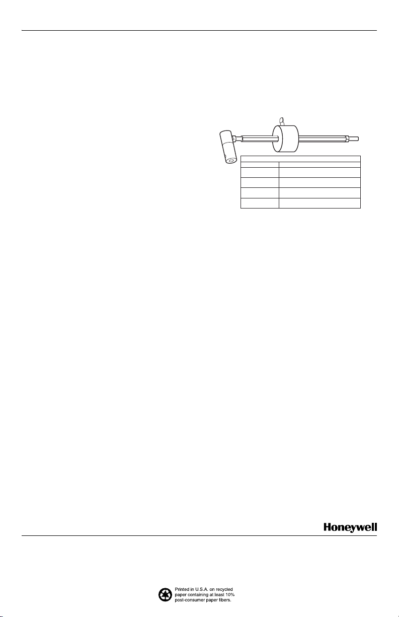
The counterweight arm assembly and counterweight only
are available as replacement parts. See Fig. 3.
Table 1. SPRD Damper Sizing.
Rectangular Recommended cfm Round Recommended cfm
12 x 8 1000 7 300
12 x 10 1200 8 400
12 x 12 1400 9 600
20 x 8 1600 10 750
20 x 10 2000 12 1200
20 x 12 3000 14 1800
— — 16 2400
INSTALLATION
When Installing This Product…
1. Read these instructions carefully. Failure to follow
them could cause a hazardous condition.
2. Check that all components are included. The
SPRD package includes: SPRD damper, counterweight arm assembly and installation instructions.
3. Check the ratings given in the instructions and on
the product to make sure the product is suitable for
your application.
4. Installer must be a trained, experienced service
technician.
5. After installation is complete, check out the product
operation as provided in these instructions.
Selecting Damper Size
1. Size the bypass damper by subtracting the cfm of
the smallest zone from the cfm of the system.
2. Consult Table 1 to determine the correct rectangular or round SPRD to use.
3. Alternately, calculate the bypass damper size using
a duct-sizing calculator. Use.25 in. for a bypass
zone and.1 in. for a dump zone.
® U.S. Registered Trademark
Copyright © 2003 Honeywell International Inc. • • All Rights Reserved
69-1518-2
Page 2

STATIC PRESSURE REGULATING DAMPER (SPRD)
CA
SIZE
12 X 8
12 X 10
12 X 12
20 X 8
20 X 10
20 X 12
A
7-31/32
9-31/32
11-31/32
7-31/32
9-31/32
11-31/32
c
B
SPRD DIMENSIONS IN IN.
C
D
B
8
11-27/32
6
10
12
8
19-27/32
10
12
A
E
E2F
4
Fig. 1. Rectangular damper dimensions in in.
F E
B
D
GH
SIZE
A
6
6
7
7
8
8
9
9
10
10
12
12
14
14
16
16
SPRD DIMENSIONS IN IN.
C
B
3/4D8
2-3/8
E
1-3/4F1-3/4G4
8
10
10
12
D
F
M14868A
H
4
4.5
4.5
5
5
5.5
5.5
6
6
7
7
8
8
9
9
M14869
Fig. 2. Round damper dimensions in in.
69-1518-2 2
Page 3

STATIC PRESSURE REGULATING DAMPER (SPRD)
Selecting Damper Location
Install the SPRD in the ductwork or plenum upstream of
any zone dampers and downstream of the air handler or
furnace. Then run a duct from the SPRD into the return. It
is preferable to place it as far as practical from the air
handler.
The round SPRD can be mounted in vertical or horizontal
ductwork. The rectangular SPRD can be mounted only in
horizontal ductwork. Be sure there is adequate room for
the weight arm to swing freely.
The equipment should be protected from freeze-up and
from tripping the high limit with a C7735 on the TZ-3,
TZ-4, EZ-2, EZ-4, EMM-3, and EMM-3U or with a C7835
on network zoning systems.
Alternatively, the SPRD can dump air from the supply to
a non-critical temperature area such as a hallway,
basement, or false ceiling (in commercial applications).
Honeywell does not recommend using dump zones.
Mounting the Damper
Rectangular SPRD
1. Cut a 4 in. opening into the side of the air duct. Be
sure the opening is cut fully to the top and bottom
of the duct. (See Fig. 1 for damper dimensions.)
2. Slide the damper into the opening
3. Secure the mounting plate to the air duct using the
six no. 8 18 x 1/2 sheet metal screws (included).
Round SPRD
1. Install a duct collar into the duct. See Fig. 2 for
damper dimensions.
2. Slide the damper onto the duct collar
3. Secure the damper using no. 8 18 x 1/2 sheet
metal screws (not included) through the damper
and duct collar.
Settings/Adjustment
After the damper is installed into the duct, assemble the
counter-weight subassembly into the damper:
1. Remove the counterweight subassembly from the
carton.
2. Loosen the set screw on the extension so the
extension can slip over the damper shaft.
3. Place the extension on the desired side of the
damper shaft.
4. Adjust the angle of the counterweight to approximately 45 degrees from the vertical down position
and tighten the set screw to 40+/- 10 in. lb torque.
5. Adjust the counterweight by loosening the thumb
screw on the counterweight, moving the counterweight to the desired position and retightening the
thumb screw.
a. Move the counterweight toward the end of the
arm to increase the damper closing force.
b. Move the counterweight toward the damper
shaft to decrease the damper closing force.
6. Set the thermostats so only the smallest zone is
calling for circulation fan or air conditioning. The
SPRD should be partially or fully open. The velocity
from the registers should be acceptable. Adjust the
SPRD, if necessary.
7. Set all thermostats to call for circulation fan or air
conditioning. The SPRD should now be closed.
3 69-1518-2
Page 4
CHECKOUT
After completing the installation, be sure the equipment
operates correctly:
1. The damper opens fully or partially when the smallest zone of the system is calling, then closes as the
other zones call.
2. When all zones are calling, the damper is fully
closed.
REPLACEMENT PARTS (FIG. 3)
Both the counterweight arm assembly and the
counterweight are available as replacement parts. See
Fig. 3 for part numbers. If the counterweight arm
assembly is used on the rectangular SPRD, remove the
coupling extension because it is used only for the round
SPRD. Remove the extension from the coupling by
loosening the setscrew nearest the counterweight arm
using a 1/8 in. Allen wrench (not included).
COUNTERWEIGHT ARM ASSEMBLY (INCLUDES WEIGHT)
PART NO. USED WITH
32005981-002
(ASSEMBLY)
32005981-003
(ASSEMBLY)
32005981-004
(ASSEMBLY)
32005688-001
(WEIGHT ONLY)
SPRD6, SPRD7,
SPRD12X8, SPRD20X8
SPRD8, SPRD9,
SPRD12X10, SPRD20X10
SPRD10, SPRD12, SPRD14, SPRD16
SPRD12X12, SPRD20X12
ALL SPRD DAMPERS
Fig. 3. SPRD replacement parts.
M19643
Automation and Control Solutions
Honeywell International Inc. Honeywell Limited-Honeywell Limitée
1985 Douglas Drive North 35 Dynamic Drive
Golden Valley, MN 55422 Scarborough, Ontario
M1V 4Z9
69-1518-2 G.H. Rev. 7-03 www.honeywell.com/yourhome
 Loading...