


Installation Guide and Operating Manual
Multi-S p ect r u m Di gi t al
Electro-Opt i c al Fire D ete ct ors
Models SS2-A, SS2-AN, SS2-AH , and SS2-AM
Stand-Alone Mode

OPERATOR MANUAL // NOTICES AND TRADEMARKS
Notices and Trademarks
Copyright 2014 by Honeywell International Inc.
Wh ile th is inform at ion is pr esen t ed in g ood fai th and believ ed to b e
accu rat e, H oney well di sc laim s the im p lied warran ti es of m erc h ant ab ili ty
and fitn es s for a p art ic ul ar pu rp ose an d mak es n o expr ess warran t ies
excep t as may be s t ated in i ts writt en ag reem en t with and for i ts
customers.
In no even t is H oney well li ab le t o an yone for any in d irec t, spec ial or
cons eq uent ial dam ag es. The in form at ion an d sp eci ficat ion s in thi s
docum en t are s ub j ect to ch ang e with ou t not ic e.
The det ect or m u st be i ns tal led on ly by qu alifi ed p rofes si on al p ers on n el in
accord an ce wit h l ocal cod es.
The prot ect ion p rovid ed b y th e gas d et ect or may b e im p aired if it is used i n
a mann er n ot sp eci fied by Hon eywell Analytics.
ACCTTL, ALERT-1, ALARM-2, ALERT-1: ALARM 2, ALERT-1: ALA RM -2,
ATAG , C lean Room Sen tr y, COP -i, Complete Optical Path Integ rity, CM1,
CM1-A , DartL og ic, Fi reL ogi c, Fi re S ign atur e An alys is, Fi reB usI , F ireB usI I,
FirePic, FirePicII , FirePicIII , Fir ePi x, Fi rePi ct u re, FS C, Fir e Sent ry
Corpor ation , Fi re Sen t ry Corp . , F SX, All FSX Nom encl atu re V ariat ion s
(such as: FS2, FS2X, FS3, FS3X, FS4, FS4X, FS5, FS5X, FS6, FS6X,
FS7, FS7X, FS8, FS8X, FS9, FS9X, FS10X, FS10X, FS11, FS11X, FS12,
FS12 X, FS14 , FS14X, FS15, FS15X, FS16, FS16X, FS17, FS17X FS18,
FS18 X, F S19 , FS 19X, FS20 , FS20X , FS 24, F S24X , FS24X N, FS26 ,
FS26X, FS26XN ) , FS7-2173-2RP, FS System 7, FS System 10, FS7-2173,
FS7-2173-RP, FS20 00 , FS S yst em 2000, Hig h Speed F lam e &
Su rveillan c e Detec t or, Multi-Sp ect rum Qu adB and Tri pl e IR , Mu lt i -Spectrum
TriBand, Multi-Spectrum Tri-Ban d , Near B an d Infrar ed, Near B an d IR ,
NearBand IR, QuadBand IR, Room Sentry, RS, RS2, SM2, SM3, SS, SS2,
SS2X, SS2-A, SS3, SS3-A, SS3X , SS 4, SS 4 -A, SS4X, SnapShot, SLR-BIT,
Sup erB u s, Sup erS ent ry, Syst em 2000 , Tri -Mod e P lot , Quad B and Tripl e IR
Plus, TriBand, Tri-Band, “F S & FSC t riang le l ogo’ s”, WB IR , W ide B and
Infrar ed , W id eB and I R, W ide B and I R
are regis t er ed t rad em ark s of Hon ey well In t ern ati onal In c.
Other brand or product names are t rad em ark s of t hei r res pec t ive own ers.
Honeywell Analytics
HONEYWELL 1

Symbol Definitions
The following table lists those symbols used in this document to denote
certain conditions.
Symbol Definition
OPERATOR MANUAL // SYMBOL DEFINITIONS
ATTENTION: Id enti fies in form at ion t h at requ ir es
spec ial c on sid erat ion .
In d icat es a s itu ati on which , i f not avoid ed, may
resul t i n equi pm ent or work (d ata) on t h e syst em
bein g damag ed or los t, or may res ul t i n th e
inab il ity t o p rop erly operat e th e p roces s.
CAUTION: Ind icat es a pot en t ially h azar dou s
situ at ion whi ch, if n ot avoid ed , m ay resu lt in
min or or mod erate i nj u ry. I t m ay also b e u sed to
alert ag ain s t un safe p rac ti ces .
CAUTION: Symbol on th e equi pm en t refers t h e
user t o t h e prod uct manu al for ad d it ion al
inform at ion . The sym b ol ap p ears n ext to
requ ired in form at ion in th e m anu al.
HONEYWELL 2

TAB LE O F CONTENTS
TABLE OF CONTENTS
OPERATOR MANUAL //
T ABL E OF C ON TE NTS ............................................................... 3
APPROVALS .............................................................................. 4
SECTION 1: FAM ILIARIZATION ...................................................................... 5
1.1 Introduction ............................................................................................. 5
1.2 Stand-Alone Operation ............................................................................. 5
1.3 FS2000 System Operati on ....................................................................... 6
1.4 Overview6
1.4.1 Model SS2 Detector Status Indications ................................. 6
1.4.2 Detection Range .................................................................. 6
1.4.3 Field-of-View ....................................................................... 6
1.5 Testing 7
1.5.1 Special Conditions for Testing .............................................. 7
1.5.2 Automatic Testing ................................................................ 7
1.5.3 Manual Testing .................................................................... 7
SECTION 2 : INSTALLATION ............................................................................ 9
2.1 Installation Procedure .............................................................................. 9
2.1.1 Installation Precautions........................................................ 9
2.1.2 Conduit Installation .............................................................. 9
2.1.3 Wiring Recommendati ons .................................................... 9
2.1.4 Power Supply Considerati ons............................................... 9
2.2 Enclosure Installati on (Optional) ............................................................. 10
2.2.1. Swivel Mount (SM2): .......................................................... 10
2.2.2 Install Conduit (If not already installed)............................... 10
Figure 2. Model SS2 Detector with SM2 Swivel Mount .................... 10
2.3 Wiring Detectors .................................................................................... 10
Figure 3: Model SS2 Detector Enclosure - Side View ....................... 11
Figure 4. Model SS2 Detector Enclosure - Back View ...................... 12
Figure 5. Models SS2-A, SS2-AN, SS2-AH, and SS2-AM................ 12
SECTION 3 / MAINTENANCE AND TROUBL ESHOOTI NG ..............................15
3.1 Personnel .............................................................................................. 15
3.2 Cleaning Windowed Enclosures and Detectors........................................ 16
3.3 SS2-A, -AN, -AH, and –AM Detectors’ Faults .......................................... 16
3.4 SS2-A, -AN, -AH, and -AM Detector Modules Replacement ..................... 17
3.5 Detector Repair ..................................................................................... 17
SECTION 4 / DETECTOR PINOUT DATA .......................................................18
SE CTIO N 5 / DE T ECTOR L ABE L D R AW IN G S ...............................................19
INDEX .....................................................................................20
HONEYWELL 3
TABLE 1: Stand-Alone Model SS2 Detector Connectors -
Pinouts.............................................................................. 18

operating equipment.
APPROVALS
OPERATOR MANUAL // APPROVALS
The Model SS 2 Opti cal F ire D etec tor s h ave b een m anu fact ur ed in
comp l ian ce wit h th e req u irem ent s of the I SO-9001 stan d ard an d h ave been
approved by:
• Cal if or nia St ate Fire M ar shal (C SFM )
• Factory Mutual (FM)
• Canadian Standards (CSA)
• CENELEC approval by FM Approvals Ltd. Certification Service
in compliance with the ATEX Directive.
Read and understand this ma nual before installing or
Marking: Class I, Div. 1 & 2, Groups A, B,C, & D
Class II, Div. 1 & 2, Groups E, F, & G
Class III
Class I , Zone 1 AEx d IIC
Ex d IIC; Ex tb IIIC T135°C
HONEYWELL 4

SECTION 1: FAMILIARIZATION
1.1 Introduction
T he Model SS2 Multi-Spec trum Electro-O p ti cal F ire/ Fl am e Detec t ors m ay
be u sed in th e FS200 0 Fir e Early W ar ni ng System or i n th e St and -Alone
mod e. D etec tor s of t hi s mod el are hou s ed in E xpl osion -Proof Class I, Div.
1 enc los ur es. The on ly d iffer enc e bet ween an FS 20 00 System M odel SS2
Detect or an d a S tand -Alon e SS2 Det ect or is in the wiri n g. The wiri ng
diffe ren ces are d esc rib ed in Sec t ions 1. 2 an d 1.3.
Model SS2-A Det ect ors hav e a lat ch in g relay. The y are us ed for
hydrocarbon and non-hydrocarb on fires
Model SS2-AN Detec tors h ave a n on -l atc h ing relay. The y are ot h er wise
iden t ical to th e SS 2-A.
Model SS2-AH is t he s ame as Mod el S S2-A excep t for th e p rog ramm ing to
assu re Hi gh Speed m il lis econ d res pon s e to non -UV emi tting s od ium az id e
fires (in addition to the n ormal fire res p ons e) f or ai r b ag ind ust ries . The
Detect or i s h ou sed in a Cl ass I, Di v. 1 Explos ion -Proof en cl osu re. For m ore
inform at ion , refer to c or res pon d in g s pec ific ati on sh eets .
OPERATOR MANUAL // SECTION 1: FAMILIARIZATION
Model SS2-AM is the s am e as Mod el SS2-A excep t for th e p rog ramm in g to
assu re Ul tra H ig h Speed mi lli secon d res p on se t o norm al n on -sodium azi de
burning materials radiating UV and IR energy for munitions and air bag
indu st ri es. The Det ect or i s h ou sed in a C lass I, Di v. 1 E xplos ion -Proof
encl osu re. For m ore i n form ati on, refer t o cor r esp on di ng spec ificat ion
sheets.
There ar e oper at ion al ad v an tag es wh en th e Det ect or is conn ec ted to an
FS20 00 Cont roller and F ireB u s. The D etec tor also h as fle xibi lity to b e reconfigured in the field. It is simple to install and operate due to built in selftest in g. Th e m aint en anc e cons is ts in wip in g the l ens and perform in g
period ic t est ing req u ired b y the m anu fact u re of th e F ire Con t rol an d
Sup pression Systems.
There ar e oper at ion al ad v an tag es wh en th e Det ect or is conn ec ted to an
FS20 00 Cont roller and Fir eBu s . The Det ect ors also h av e fl exib il it y to b e reconfigured in the field. The maintenance consists in wiping the lens and
perform in g p eriod ic t est ing req u ired by th e manu fact u re of t he F ire C ont rol
and Suppression Systems.
1.2 Stand-Alone Operation
The Model SS 2 Det ect ors may be c on nec ted t o an app roved F ire/ S ecu rit y
Pan el for S tan d -Alone op erat ion . The Det ect ors oper ate on 2 4 V olt s DC. In
thi s mod e th e Det ect ors util iz e Fire an d Fau l t rel ays to i nt erfac e to F M/U L
approved Fir e/S ecu ri ty P an els. For St and -A lon e op erat ion , the D etec tor ’s
Fault rel ay is automatically configured by the on-b oard m ic rop roces sor .
The input current of the Detector is about 15 mA higher in the Stand-Alone
mod e com par ed t o op erat ion as part of FS 2 000 System .
HONEYWELL 5

OPERATOR MANUAL // SECTION 1: FAMILIARIZAT ION
1.3 FS200 0 S y st em Operation
For FS 2000 S yst em op erat ion , th e Det ect or’ s Fi re an d Fau lt si gnal s are
sent dig it all y to th e F S2000 Syst em Con t roller us ing th e four wire F S 20 00
FireB us . The Fi reBu s p rovid es t h e 24 Volts DC power for t h e Detec t or an d
RS-4 85 dig it al comm un icat ion (R efer to Hon eywell Analytics document
MN0003: "FS2000 FIRE EARLY WARNING SYSTEM - INSTALLATION and
OPE RATIO NS GUI DE" ). F or spec ial rem ote al arm ap p lic ati ons , us ers may
also con n ect d irec tl y to t he D etec tor ’s F ire al arm rela y.
NOTE: Wh en th e Mod el S S2 Det ect or is conn ect ed t o the F S2000
System usi ng FireB u s commu n ic ati on, th e Con t roll er automatically
de-energ izes th e D etec tor’ s F aul t r elay.
1.4 Overview
1.4.1 Model SS2 Detector Status Indications
The Model SS2 Multi-Spectrum Optical Fi re/ Flam e Det ec tors are
microprocessor-bas ed devic es, whic h see u lt ravio let (UV ), vis ible (V IS ),
and in frared (I R) s pec tr al reg ion s . The Det ect or's log ic processor is
capab le of q u ic k res p ons e to fires wh ile vi rt u ally el im i nat ing fals e alarm s .
The Model SS 2 Det ect or h as a 120 ° field -of-view.
There ar e t wo (2) LE D s on the Mod el S S2 Det ect or for in d ic ati on of th e
Detect or s tat u s. During Normal Op erat ion b oth LE Ds will b lin k ever y 10
seconds.
If a Model SS 2 D etec tor h as a Fau lt , it de-energizes the Fau lt rel ay and
turns one (1) LED on. (The LED will not light if the Fault is a “No Powe r
Fault ”) . I f th e Faul t c ond it ion , such as a “Low Volt ag e Fau lt ”, is elim inat ed ,
the D etec tor will au tom at ic all y ret u rn to Nor m al Op erat ion .
Fault s cau sed b y E xcess ive In p ut Vol tag e or t em p erat ur es ou tsid e th e
operat in g temp erat u re ran g e requ ire fac tor y re -cert ific ation . Both LEDs
rapidly blinking (with frequency about 2 Hz) indicate faults requiring recertification.
If a Model S S2 D etec tor al arm s t o a fire, it energizes the Fir e rela y and
turns on both LEDs in the following sequence. One LED is turned on
imm edi atel y and th e s econd LE D will rap id ly bl in k for s e veral sec ond s
indicating that th e Det ector's FirePic is being permanent ly st ored in th e
Detect or's sol id -s tat e m em ory. (Fi rePi c is t he s everal secon d s of Det ect or
data, whi ch prec ede an al arm event .)
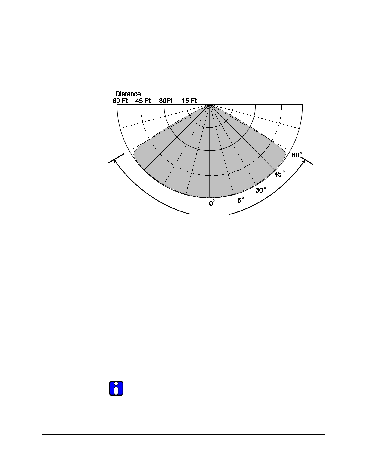
1.4.2 Detection Range
The det ect ion ran g e of th e d et ect or is 60 feet t o an i nd ust rial s t and ard of
one sq u are foot g asol in e p an fir e with in 5 sec ond s.
1.4.3 Field-of-View
The Detec tor in corp orates a m in imum 120 -d eg ree con i cal F ield of V iew.
The fir e em iss ion s r eceiv ed by t he D etec t or d imin ish at extrem e ed g es of
the fi eld -of-vi ew. For t h e fast est resp on se t im es t o the sm alles t siz e fire,
HONEYWELL 6
OPERATOR MANUAL // SECTION 1: FAMILIARIZATION
120 Degrees
the D etec tor sh ou ld be p oin t ed to th e fire t h reat ar ea. W h en mult ip le
detec t ors are u s ed to c over larg e ar eas, th e F ield s -of-View should overlap.
The Field -of-Vie w is n ot l im it ed to 120 d eg rees. Larg er fir es ou t sid e
Figure 1. Field of View, Horizontal and Vertical.
Maxim um Sen si tivit y to 1 Sq . Ft . Gas olin e P an Fire
1.5 Testing
1.5.1 Special Condition s for Tes ting
The SS 2 Det ect or shou ld b e t est ed imm edi atel y aft er in st all ati on , aft er
repair or m ain ten an c e in volving wirin g or m od u le rep lac em ent , aft er
period ic m ain t enanc e, or after l en s con t am inat ion has b een iden t ified .
1.5.2 Automatic Testin g
The Model SS 2 Det ect ors cont ain an int ern al sou rc e for sel f-testing. For
test in g the M odel SS2 Det ec tors end -to-end for both optical path and
window cl ean l in ess , u s e a Honeywell Analytics M odel FT-2045 Test Lamp.
1.5.3 Manual Testing
For m anu al tes tin g the Det ec tor m ay b e expos ed to an act u al indu s tr y
stan d ard open flam e or t o a Test L am p sim u lat ing a fire. For Honeywell
Analytics model SS2 Multi-Spectrum Fi re Det ect ors , i t i s mand at ory to u se
the h andh eld UV/ I R Test Lam p, Mod el No FT-2045 or FT-2145.
NOTE: Other m anufacturers UV/IR Test Lamps should not be
HONEYWELL 7
utilized to test Honeywell Analytics Det ect ors, an d Honeywell
Analytics Model F T-2045 and FT-2145 Test Lamps should not be
uti liz ed for tes ti ng ot h er manu fact u rer’ s Det ect ors .

OPERATOR MANUAL // SECTION 1: FAMILIARIZATION
The FT-2045 and FT-2 14 5 Test L amp s are h ou sed in an Exp losi on -proof
encl osu re, p owered b y in tern al rech arg eab le b at teri es, an d d es ign ed for
ind oor an d outd oor u s e. For ad d it ion al in form at ion on th e Test L amp , refer
to Honeywell Analytics Sp ecific at ion SP0 242 for t he F T-2 0 45 or 1505 -008A
for the F T-2145.
HONEYWELL 8

SECTION 2: INSTALLATION
2.1 Installation Procedure
This s ect ion d esc rib es th e ins tal lat ion of th e Mod el S S2 Det ect ors for t h e
Stand-A lon e mod e. Ut iliz at ion of ju nct ion boxes is recom m en d ed for th e
Detect ors wiri n g.
2.1.1 Installation Preca utions
The foll owin g p recau t ion s sh ou ld b e obs erved dur in g in stall ati on of Mod el
SS2 D etec tor s.
OPERATOR MANUAL // SECTION 2: INSTALLATION
1. Make su re t h at exter n al elec tri ca l p ower is t u rn ed
OFF b efo re con n ect in g t o
the D etec tor .
2. Do not handle the Detector's module (with its printed circuit boards)
without grounding. Printed circuit board components are susceptible to
dam ag e from elect ros tat ic d isch arg e.
2.1.2 Conduit Installation
The foll owin g recom mend ati on s shou l d be ob s erved wh en p lann i ng
conduits.
1. In c ase on ly on e of th e t wo 3/ 4 inch N PT cond u it op en ing s on th e Det ector
encl osu re is u sed, seal t h e unu sed op en ing with a th read ed plug and
app roved s ealin g m at erial.
2. In ar eas wher e m oist u re m ay acc um ul ate, in stal l an app roved c on du it trap
or drain .
3. For app li cat ion s r equ i ring a Clas s I, Div. 1 Exp los ion -Proof rat in g, in s tal l a
seal with in 6 in ches of th e en cl osu re.
2.1.3 Wiring Recommendations
Ins t all a jun c ti on box n ear eac h D etec tor locat ion . W ire eac h D etec tor to
the j un ct ion b ox. Us e sc rew-down terminal strips inside the junction box to
make t h e conn ect ion s to th e Det ect or's ter m in als and an Ap p roved F ire
Alarm P anel. Us e onl y app roved ju n ct ion b oxes an d term in al st ri ps.
Avoid w i re spl ices. Howe ve r, i f wi re sp lice s a re ne cessa r y, Honeywell
Analytics recommends soldering all spl ices. The use of g ood wiring
pract ic es will g reatl y im p rove t h e ease an d reliab il ity of in st allat i on , an d
facilitate servicing .
2.1.4 Power Supply Considerations
Model SS2 Detectors use 24 Volts DC at a maximum current of 100
milliamps. Make sure that the Panel's power supply can handle the current
load of the total number of Detectors connected to it. For example, if 10
Detectors are used on one Panel's power supply, (multiply 100 mA 10 times)
the Panel's power supply must be able to handle at least 1,000 mA (1.0
A). This current load must also be considered while calculating the Panel's
24-hour backup power requirements.
HONEYWELL 9

OPERATOR MANUAL // SECTION 2: INSTALLATION
2.2 Enclosu r e Inst al l ati o n (Optional)
2.2.1. Swivel Mount (SM2):
a. Select fasteners for the swivel mounting such that they will secure it
to the typ e of material at t he enclosure location.
b. Mount the swivel-mou n t to th e wall ass ur in g correc t orien t ation .
c. In st all th e mou nt ing brac ket ont o th e Mod el S S2 Detec t or
enclosure using the #¼-20 or #6 mm s crews and nuts provided.
If orien ted c orrec tl y, th e ou ts ide c on tours of th e mou nt ing ears
on th e D etec tor en c los ur e and th e end s of t he br ack et will
match. The l arg e d iam eter of th e th read ed i n sert shou ld fac e
the en c losu r e.
d. Screw th e en c losu re/ b rack et assem b ly ont o t he bal l or s wive l
stud . Turn t h e Detec t or un ti l the st ud bott oms ag ai ns t the
enclosure. Do not tighten. While hol ding the enclosure, tighten
the j am nut ag ains t the brac ket .
e. Wh il e hold ing th e enc los ur e, l oosen the s ock et h ead screw on
the SM2 swivel-mount. Posit ion th e enc los ur e in such a way
that th e cond u it op en ing s are locat ed hor izon t all y at th e b ot tom.
Poin t th e en cl osu re in th e d esi red direc ti on an d t igh t en the
app rop riat e h ard ware.
2.2.2 Instal l Condui t
(If not alre ady ins talled).
Figure 2. Model SS2 Detector with SM4 Swivel Mount
2.3 Wiring Detectors
To wire a Mod el S S 2 Det ect or, rem ove its m odu le from th e enc los ur e. After
wiring conn ect ion s r e-in s tal l th e mod ul e in th e enc los u re.
HONEYWELL 10

OPERATOR MANUAL // SECTION 2: INSTALLATION
2.09
4.66
1.10
0.67
4.38
2.40
¾ NPT
1.50
Obs erve st at ic p rot ect ion s afegu ard s while h an d ling M odel SS2 Det ec tor
modules. W ear a g roun d ed wrist st rap .
NOTE: The su p pl y conn ect ion wirin g shall b e rated at leas t 10 °C
above t h e rat ed s ervice t em p erat u re (9 5 °C for T4 app li cat ion s and
85°C for T5 applications). See F ig u res 6 and 7 on P ag e 11 of th is
Ins ruc ti on M anual .
Caution: Do n ot t ou ch th e det ec tor el em en ts on the fron t of th e
Model S S 2 Det ect or m odu les . If t ouch ed ac cid en t ally, clean t h em
per in st ruct ed of Sec ti on 3 .2.
Figure 3: Mod el SS2 Detector E nclosure - Side View
HONEYWELL 11

OPERATOR MANUAL // SECTION 2: INSTALLATION
igure 4. Model SS2 Detector Enclos ure - Back Vie w
F
Figure 5. Models SS2-A , SS2-AN, SS 2 -AH, and SS2-AM.
HONEYWELL 12

OPERATOR MANUAL // SECTION 2: INSTALLATION
1. REMOVE THE DETECTOR MODULE FROM ITS ENCLOSURE.
a. Wi th elec t ric al p ower of f, l oos en th e A llen -h ead sc rew at t he b as
f t he m et al en c losu re t op wind owed cover. (Mak e su re t h at
o
electr ical po we r is off b y obs er vin g th at the D etec tor' s L E D's d
OT bli nk for at least 1 5 sec ond s. )
N
b. Unscrew the top windowed cover and set it aside with its "O" ring.
Keep both cl ean .
c. Loos en the modu les’ th ree c ap ti ve screws; sc re ws sh ou ld not b
r
emoved fr om t h e ci rcui t board .
d. Carefu lly lift ou t th e modu l e, s lid ing i t al ong th e t hr ee m etal
standoffs.
IRE THE DETECTOR MODULE.
2. W
a. In sert th e cab les int o the m et al en c losu re bas e th roug h on e of th
c
onduit openings.
b. Conn ect th e 24-volt D. C. P ower Su pp ly wires to t h e J1 c onn ect or
and firm ly t igh ten down t h e two sl ott ed sc rews with a small
screwdriver. DO NOT CONNECT ANY WIRES TO J1-Pi n 2 o r J1 -
Pin 3 . Do NOT over ti gh t en t o pr event st ripp ing or b reak ing . (See
F
igu re 4 ab ove.)
Pin 1 Pin 2 Pin 3 Pin 4
Black Green or B lu e Wh ite or Yell ow Red
Ground (-) NOT USED NOT USED Powe r (+)
e
o
e
e
3. WIRE THE DETECTOR FIRE RELAY (All Models)
a. In sert th e Fir e Al arm relay cab l es in t o th e met al en c losu re bas
t
hrough one of the conduit openings.
b. Conn ect th e wires t o th e fou r p in WECO term in al J3 . Ins tal l t h
w
ires in t o J3 Pin s 1 and 2 ( for Norm all y O p en r elays) and firm ly
tig hten down t h e sl ott ed sc rews wi th a sm all s crewd ri ver.
4. WIRE THE DETECTOR FAULT RELAY (SS2 -AM and -AH)
a. In sert th e Fau lt rel ay cab l es in t o th e met al en c losu re bas e t hr ough
e of the c on dui t op en ing s.
on
b. Conn ect th e wires t o th e fou r p in WECO term in al J2 . Ins tal l t h
w
ires in t o J2 Pin s 1 and 2 an d firm l y tig h ten down the s lot ted
screws with a small screwdriver.
e
e
e
HONEYWELL 13

OPERATOR MANUAL // SECTION 2: INSTALLATION
5. REPLACE THE DETECTOR MODULE INTO THE ENCLOSURE.
a. Care ful ly in st all t h e m odu le b ack over th e t hr ee metal st an doffs and
screw it down with the three ch rom e-plat ed sc rews in t o th
s
tandoffs.
e
b. If nec ess ary, c le an th e det ect ors an d win dowed cover accord in g t
the instructions in Section 3.2.
c. Sc rew do wn t h e metal enc los u re top win d owed c over u n ti l sec u r
d tig hten th e allen -head "t amp er-proof" sc re w.
an
o
e
HONEYWELL 14

OPERATOR MANUAL // SECTION 3 / MAINTENANCE AND
TROUBLESHOOTING
SECTION 3 / M AINTENANCE AN D TROUBLESHOOTING
3.1 Personnel
Troub l esh ooti n g, t est ing, and main t enanc e mu st b e perform ed on ly b y
qualified authorized personnel obs ervin g st and ard safet y practices.
Alt hough Mod el SS2 Det ec tors op erat e on s afe 24 V olt s D C, the F M/ UL
App roved F ire A larm P an el's p ower su pp ly m ay op erate on a li fe thr eaten in g 12 0 or 24 0 Volt s AC.
WARNING: H azard ou s volt ag es m ay b e p resen t du ring test ing
proced u res . S eri ous inj ur y or deat h may resu lt if p erson n el fai l to
observ e saf et y prec au ti ons .
CAUTION: Model SS 2 Det ect or modu les an d thei r com p on ent s are
sus cep t ible t o p erman en t dam age du e t o elec tros t ati c d is charg e
(ESD).
DO NOT hand l e a m odul e with ou t ad equ at e grou ndi ng precau t ion s.
If Model SS 2 Mod u le m ust be sh ipp ed bac k t o the fac tory for r ep air,
it MUS T be p ac ked i n st ati c prot ect ed mat erial. I f st ati c p rot ect ed
mat erial i s n ot avail abl e, c are fu lly wrap t h e Mod ul e with alum i num
foil.
HONEYWELL 15

OPERATOR MANUAL // SECTION 3 / MAINTENANCE AND
TROUBLESHOOTING
3.2 Cleaning Windo wed Enc losures and Det ectors
Opt ic al win d ows on t h e Mod el SS2 Det ect or sh ou ld be c lean ed per iod ic ally
accord in g t o a regul ar m aint en an ce sch edu l e. For cl ean ar ea app l icat ion s ,
perh ap s mont h ly b asis will b e su ffic ien t. For extrem el y con t am in at ed
application environments, such as truck filling stations with presence of
blac k c arb oneou s smok e, dai ly clean i ng s ch edu le may b e nec ess ary.
Clean t he window of the Model SS2 Detect ors each tim e th ey are han d led ,
the win d ows ap pear con t am in ated, or th e Det ect or fails an end-to-end tes t
with a Han d h eld Test er.
Clean t h e Det ect or Mod u le's S ens or each t ime D etec tor s h ave been
disassem b led for wiri ng or r epl acem en t .
Use a b last of an air h ose or an oi l-free cl ot h t o clean th e en clos u re
window. Oil d egr ades th e perfor m anc e of UV Det ect ors. O cc asion all y, t he
use of a s ol vent , s u ch as alcoh ol i s ac cep t able. No d isas sem bl y of th e
Model SS 2 Det ec tor i s req u ir ed.
NOT USE SILICONE-BASED OR COMMERCIAL
DO
WINDOW CLEANING PRODUCTS. THEY WILL
DEGRADE THE MODEL SS2 DETECTOR
PERFORMANCE.
WARNING: Pot en ti al elec tr ost ati c h azar d. Do not rub with dry cl oth .
3.3 SS2-A, -AN, -AH, a nd –AM Detectors’ Fa ults
Model SS2 Detectors will indicat e a Fault (or Trouble) conditi on by de-energizing
its Fault Relay (J2 con nect or ) . The following are Detector Faults:
a. Temperature Fault: The Detec tor will Fau lt if t he i n tern al
temperature dur ing op erati on is ab ove 8 5° C or below -40°C.
Requ ires fact or y re-cert ificat ion to c orrec t. (B oth LE D’ s bli n k
rapidly.)
b. Relay Fault: The Detector will Fault if one of its Relay circu it fails. (One
LED is on until the fault is corrected. ) R eturn to factor y for s ervice.
a. Excess iv e In pu t Vol tag e Fau l t: The Detector will Fault if the
voltag e s upp l ied to i t is t oo h igh. Requi res fac tor y recerti ficat i on to c orrec t. (B ot h LE D’ s blin k rap i dl y.)
c. No Power Fault: The D etec tor wil l F au lt if th e volt ag e su pp lied t o it
is in ter ru pted or tu rn ed off. (N o L ED in d icat ion. )
d. Self-Checking Fault: The Detector will fault if its internal
mic rocom pu t er s elf-ch ec kin g c irc ui try an d soft ware fin d s a fai lu re.
HONEYWELL 16

OPERATOR MANUAL // SECTION 3 / MAINTENANCE AND
TROUBLESHOOTING
3.4 SS2-A, -AN, -AH, a nd -AM Det e ctor Modules Repla ce me nt
CAUTION: Model SS 2 -A, -AN, -A H, and -AM Det ect or modu les an d
thei r com pon en t s are su sc ep tib le to p erm anen t d amag e du e to
electr ost ati c d is ch arg e (E S D). DO NOT hand le wit h out ad equ ate
grounding precautions.
1. Wi th p ower off, loos en t h e Al len -head s crew at t h e b ase of t h
e
met al en cl osu re t op win d owed c over. (D oub le-ch eck an d make s u re
t
hat th e Det ect or's L EDs d o
NOT blink for at leas t 1 0 sec on d s.)
2. Unscrew the top windowed cover and set aside with its "O" ring.
Keep both cl ean .
3. Loos en an d remove t h e th ree s lot head ed sc rews loc ated on th e
t
op ci rcu it b oard . (Som e mod els use cap t ive sc rews t hat s hou ld not
be rem oved fr om th e circ uit b oard).
4. Care ful ly li ft ou t th e modu l e, s lid ing i t al ong th e t hr ee m etal
standoffs.
5. Disc on n ect all of t he wires fr om th e fem ale j ack s loc ated on th
b
ottom of t h e m odu le. Be s u re to not e th e con n ect ion l ocat ion of
e
each wir e.
6. In st all an oth er m odu le. Rec on nec t the wires to t h e n ew mod u le.
Make su re t h e mod ul e is corr ect ly al ig n ed. Car eful ly re -in stall back
over th e t h ree m etal st and offs. R e-i ns t all t h e three c h rom e-plated
screws. Be careful not to touc h the sensor elements. If th ey ar
cid ent all y tou ch ed , clean as in st ruc ted i n Sec ti on 3.2 .
ac
7. Sc rew do wn t h e metal enc los u re top win d owed c over u n ti l it is
secure and tighten the Allen-h ead " t amp er-p roof" sc re w.
e
3.5 Dete ctor Rep air
Return the defective module to the factory for repair service.
The re ar e NO user serviceable parts in a Detector module.
If a Model SS 2 Mod u le mus t be sh ipp ed b ack t o the fact or y for rep air, it
MUST b e pac ked in s tat ic p rotec t ive m ateri al. If t hi s mat eri al is not
availab le, car efu ll y wrap t h e Mod u le with alum i num foil. An R MA (Return
Materia l A u th oriz ati on) is req u ir ed for al l ret u rn s t o the fac tor y. Con t act th e
Honeywell Analytics Cus tom er Ser vice D ep art m en t or you r Di st ribu t or for
an RMA numb er b efore s hi pp i ng a un it b ac k to th e factor y.
HONEYWELL 17

OPERATOR MANUAL // SECTION 4 / DETECTOR PINO UT DATA
SECTION 4 / DETECTOR PINOUT DATA
TABLE 1: Stand-Alone Model SS2 D etector Connectors - Pinouts
J1
: DETECTOR INPUT POWER
PIN
1 D. C. Retu rn or Groun d ( -)
2 NOT USED (Do not connect anything to this Pin.)
3 NOT USED (Do not connect anything to this Pin.)
4 Power (+24 Volts D.C.)
J2
: FAULT RELAY J2: F I R E RE L AY # 2
(SS2-A, -AN, -AM, -AML, AH) (SS2-AMD, -AMDL, -AHD)
PIN PIN
1 Fau lt Relay Com m on 1 Fir e Rela y #2 Com m on
2 Fault Relay Normally Closed 2 Fire Relay #2 Normally Open
3 Fault Relay Com m on 3 Fire R ela y #2 Common
4 Fault Relay Normally Open 4 Fire Relay #2 Normally Closed
J3
: FIRE RELAY
PIN
1 Fir e Rela y Com m on
2 Fire Relay Normally Open
3 Fir e Rela y Com m on
4 Fire Relay Normally Closed
HONEYWELL 18

OPERATOR MANUAL // SECTION 5 / DETECTOR LABEL DRAWINGS
BackColor
SECTION 5 / DETECTOR LABEL DRAWINGS
Part
Number
LB-6093-
049
LB-6093-
050
LB-6093-
051
LB-6093-
052
Model
Number
SS2
SS2
SS2
SS2
Material
0.020' A l
1100-Hl4
0.020' 31 6
Stai nless Ste e l
0.020' A l
1100-H14
0.020' 31 6
Stai nless Ste e l
ground
Black White 75
Polished Black 75
Black White 75
Polished Black 75
Text
Color
mA T4 T5 T6
-40°C to
+85°C
-40°C to
+85°C
-40°C to
+85°C
-40°C to
+85°C
-40°C to
+75°C
-40°C to
+75°C
-40°C to
+75°C
-40°C to
+75°C
-40°C to
+60°C
-40°C to
+60°C
-40°C to
+60°C
-40°C to
+60°C
HONEYWELL 19

INDEX
OPERATOR MANUAL // INDEX
Cleani n g P rodu c ts .................. 16
Conduit.................................... 9
Detector
Cleaning ............................. 16
Enclosure ........................... 10
LEDs .................................... 6
Maint en an ce S chedu le ........ 16
Replacement....................... 17
Status .................................. 6
Wiring ........................... 11, 18
Detector Fault
Inpu t V olt ag e ...................... 16
No Power ........................... 16
Relay .................................. 16
Self-Checking ..................... 16
ESD ........................................ 9
Explosion-Proof........................ 5
False A larm s ............................ 6
Field-of-View............................ 6
FireBus .................................... 6
FireBus
Wiring .................................. 9
FireLogic ................................. 6
Flam e Det ect or (See D etec tor ) .. 6
Grounding ................................ 9
I
nstallation ............................... 9
Conduit ................................ 9
Detector ............................. 11
Enclosure ........................... 10
Precautions .......................... 9
Stat ic Dam age ...................... 9
Layout Planning ....................... 9
Maintenance .......................... 15
Multi-Spectrum (See Det ect or) .. 6
Opt ic al F ire Det ect or
(See Det ect or) ...................... 6
Personnel - Qualified .............. 15
Power...................................... 9
Relay
FAULT .......................... 13, 18
FIRE ............................. 13, 18
Removin g Mod u les ................. 13
SS2 (S ee Det ect or) .................. 6
SS2-A ................................... 13
SS2-AH ................................. 13
SS2-AM ................................. 13
SS2-AN ................................. 13
Stand-A
lone ............................. 5
Stat ic Dam age ......................... 9
Test Sou rc e ............................. 7
Theory o f Op erat ion ................. 6
Troubleshooting ..................... 15
HONEYWELL 20

OPERATOR MANUAL // LIMITED WARRANTY
Limited Warranty
Honeywell Analytics warrants its Products against defects i n material and workmanship under normal use
and service for a period of two (2) years from the date of shipment as described herein. Honeywell Analytics,
at its option, w ill repair or replace, at no charge, such products found to be defective during the warranty
period provided that they are returned in accordance with the terms of this wa rra nt y. Rep lac ed pa r ts o r
boards are warranted for the balance of the original applicable warranty period. All Replaced parts of
Products shall become the property of Honeywell Analy tics. This express limited war ranty is extended by
Honeywell Analytics to the original purchaser only and is not assignable or transferable to any other party.
This is the complete warranty for the Products manufactured by Honeywell Analytics. Honeywell Analytics
assumes no obligations or liability for additions or modifi cations to this warranty unless made in writing and
signed by an officer of Honeywell Analytics. Honeywell Analytics does not warrant the installation,
maintenance or service of its Products. H one ywell Analytics is not responsible in any way for ancillary
equi pm en t no t fu rni sh ed b y Hone yw el l Ana l ytics, whi ch i s at tac hed to o r use d in c on nect io n wi th i ts
Product(s), or for operation of the Product(s) with ancillary equi pment and all such equipment if expres sly
excluded from this warranty. This warranty sets forth the full extent of Honeywell Analytics’ respon sibility
rega r din g th e Pr od ucts’ repair or replacem en t at Hon e ywell Anal y tics ’ op tio ns , is the e xcl us i ve rem ed y.
This Warranty is given in lieu of all other Express Warranties, Implied W arranties, incl uding without
limi t ati on , Im plie d W a rran tie s of Merc ha nt abil i t y and fi t ness fo r a pa rti cul a r pu rpos e , are li m ite d to the
duration of this Limited Warranty. In no other event shall Honeywell Analytics be liable for damages in
excess of the purchased price of the pr od uct (s ) , fo r any lo ss of us e, loss of tim e, inc on venie nc e , com m erci al
loss, lost profits or savings or other incidental, special or consequential damages aris ing out of or in
connection with the use or inability to use such product, to the full extent such may be disclaimed by law.
THIS WARRANTY DOES NOT COVER:
1. Defects or damage resulting fr om use of the Product(s) in other than its normal and customary manner.
2. Defects or damage from misuse, accident, or neglect.
3. D e fec ts or dam ag e f rom improper testing, operation, maintenance, installation, alteration, modification
or adjustment.
4. Product(s) subject to unauthorized Product modifications, disassemblies or r epairs (including, without
limi t ati on , th e aud iti on of the pr od uct of no n-Honeywell Analytics supplied equipment) which adver sely
aff ect performance of the Product(s) to interfere with Honeywell Analytics’ normal w arranty inspection
and testing of the Product(s) to verify any warranty claim.
5. Product(s) that have had the serial number removed or made illegible.
6. Freight cost to the repair faci lity.
7. A Product which due to illegal or unauthorized alteration of the software/firmware in the Product, does
not function in accordance w ith Honeywell Analytics’ specifications.
8. Scratches or other cosmetic damage to Product surfac es that do not affect the operation of the Product.
9. Normal and customary wear and tear.
Laws in the United States and other countries preserve for Honeywell Analytics certain exclusive rights for
copyrighted Honeywell Analytics software/firmware, such as the exclusive rights to reproduc e in copies and
distribute copies of such Honeywell Analytics software/firmware. Honeywell Analytics software/firmware may
be used only in the Product (s) in which the s oftware/firmware was originally embodied and suc h
software/firmware in such Product(s) may not be replaced, copied, distributed, modified in any way, or used
to produce any derivative thereof. No other use including, without limitation, alteration, modification,
reproduction, distribution, or reverse engineering of such Honeywell Analytics software/firmware or exercise
or rights in such Honeywell Analytics software/firmware is permitted. No license is granted by implication,
estoppel or otherwise under Honeywell Analytics patent rights or copyrights.

OPERATOR MANUAL // CONTACT HONEYWELL ANALYTICS
Contact Honeyw ell Analytics
Honeywell Analytics Inc.
Life Safety Distribution AG
Honeywell Analytics Asia Pacific Co., Ltd.
Americas
Honeywell Analytics Inc .
405 Barcl ay Blvd.
Lincolnshire, I llinois
USA 60069
Email: detectgas@honeywell.com
Europe
Life Safety Distribution AG
Javastrasse 2
8604 Hegnau
Switzerland
Email: gasdetection@honeywell.com
Asia Pa cific
Honeywell Analytics Asia Pacific Co., L td.
#70 1 Kol on Sc ien ce V all ey (1)
43 Digital-Ro 34 -Gil, Guro-Gu
Seou l, 15 2 -729
Korea
Email: analytics.ap@honeywell.com
Internet
Telephone
These Hon e ywel l web s it es m ay b e of int eres t t o I ndus t ry Solution
customers.
Honeywell Organization URL
Corporate www.honeywell.com
Honeywell Analytics www.honeywellanalytics.com
Cont act us b y tel eph one at th ese n umb ers .
Organization Phone Number
Americas
Europe
Asia Pacific
{32-2} 728-2711
1-800-538-0363
1-800-321-6320
+82 2 6909 0321
VOIP: +8 5401 0321

© 201 4 Hon eywell I n tern at ion al I n c.
1998M0908
Rev. A
Jul y, 20 14
 Loading...