

Honeywell SK-FIRE-CO-W Installation And Maintenance Instructions Manual
REMOTE
(+)
CAUTION
TENS ONES
9
10
11
12
13
14
15
8
7
6
5
4
3
2
1
0
9
8
7
6
5
4
3
2
1
0
INSTALLATION AND MAINTENANCE INSTRUCTIONS
I56-6602-000
SK-FIRE-CO-W
Multi-Criteria CO and Smoke Sensor
SPECIFICATIONS
Operating Voltage Range: 15 to 32 VDC
Operating Current @ 24 VDC: 200 uA (one communication every 5 seconds with green LED blink on communication)
Maximum Alarm Current: 2 mA @ 24 VDC (one communication every 5 seconds with red LED solid on)
Maximum Current: 4.5 mA @ 24 VDC (one communication every 5 seconds with amber LED solid on)
Operating Humidity Range: 15% to 90% Relative Humidity, Non-condensing
Operating Temperature Range: 32°F to 100°F (0°C to 38°C)
Air Velocity: 0 to 4000 ft./min. (0 to 1219.2 m/min.)
Height: 2.7˝ (69 mm) installed in B200S series sounder base
Diameter: 6.875˝ (175 mm) installed in B200S series sounder bases
Weight: 3.4 oz. (95 g)
Isolator Load Rating: 0.0063*
*Please refer to your isolator base/module manual for isolator calculation instructions.
UL 2075 listed for Carbon Monoxide
UL 268 listed for Open Air Protection
UL 521 listed for Heat Detectors
This sensor must be installed in compliance with the control panel system installation manual. For local audible indication of a fire and/or
carbon monoxide alarm, it is recommended to install the multi-criteria
carbon monoxide (CO) and smoke sensors into a B200S series sounder
base. If a local audible device is not used, care should be taken to develop a proper response plan. The installation must meet the requirements of the Authority Having Jurisdiction (AHJ). Sensors offer maximum
performance when installed in compliance with the National Fire Protection Association (NFPA); see NFPA 72 and NFPA 720. For a complete list
of compatible bases, refer to the Base/Sensor Cross Reference Chart at
systemsensor.com.
GENERAL DESCRIPTION DOES THIS SUPPORT CLIP MODE
Model SK-FIRE-CO-W is a plug-in type multi-criteria smoke sensor that offers
a photoelectric sensing chamber combined with a carbon monoxide (CO) sensor, 135°F (57.2°C) fixed temperature heat detector and infrared (IR) sensors,
as well as a carbon monoxide detector. The SK-FIRE-CO-W also transmits an
alarm signal due to heat (135°F/57.2°C) per UL 521.
All sensors transmit an analog representation of smoke and/or carbon monoxide density over a communication line to a control panel. Rotary dial switches
are provided for setting the sensor’s address. (See Figure 2.)
Two LEDs on the sensor are controlled by the panel to indicate sensor status.
An output is provided for connection to an optional remote LED annunciator
(P/N RA100Z).
Silent Knight panels offer different features sets across different models. As a
result, certain features of the photoelectric sensors may be available on some
control panels, but not on others.
The multi-criteria CO and smoke sensors only support SK protocol systems.
The possible features available in the multi-criteria CO and smoke sensors, if
supported by the control unit are:
1. The sensor’s LEDs can operate in three ways—on, off, and blinking—and
they can be set to red, green, or amber. This is controlled by the panel.
2. The remote output may be synchronized to the LED operation or controlled independent of the LEDs.
3. Devices are point addressable up to 159 addresses.
Please refer to the operation manual for the UL listed control panel for specific
operation. The photoelectric sensors require compatible addressable communications to function properly. Connect these sensors to listed-compatible
control panels only.
SPACING
Silent Knight recommends spacing sensors in compliance with NFPA 72. In
(9.1 m). For specific information regarding sensor spacing, placement, and
1 I56-6602-000
2/21/2019
low air flow applications with smooth ceilings, space sensors 30 feet apart
12 Clintonville Road, Northford, CT 06472-1610
Phone: 203-484-7161 Fax: 203-484-7118
www.silentknight.com
special applications, refer to NFPA 72 or the System Smoke Detector Application Guide, available from Silent Knight.
WIRING GUIDE
All wiring must be installed in compliance with the National Electrical Code,
applicable local codes, and any special requirements of the Authority Having
Jurisdiction. Proper wire gauges should be used. The installation wires should
be color-coded to limit wiring mistakes and ease system troubleshooting.
Improper connections will prevent a system from responding properly in the
event of a fire.
Remove power from the communication line before installing sensors.
1. Wire the sensor base (supplied separately) per the base wiring diagram.
(See Figure 1.)
2. Set the desired address on the sensor address switches. (See Figure 2.)
3. Install the sensor into the sensor base. Push the sensor into the base
while turning it clockwise to secure it in place.
4. After all sensors have been installed, apply power to the control panel
and activate the communication line.
5. Test the sensor(s) as described in the TESTING section of this manual.
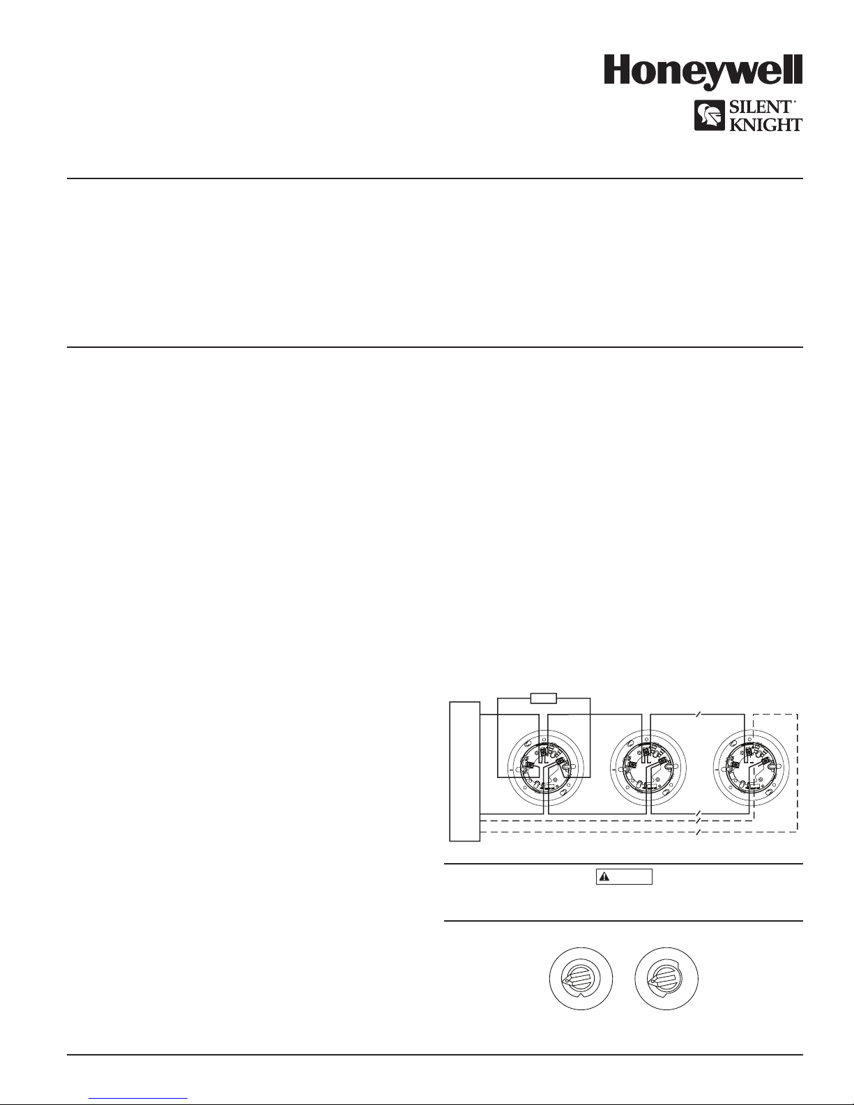
FIGURE 1. WIRING DIAGRAM
ANNUNCIATOR
+-
(+)
3
2
1
C0129-04
(–)
CONTROL PANEL
(–)
UL LISTED COMPATIBLE
2
1
3
CLASS A OPTIONAL WIRING
2
1
3
Do not loop wire under terminal 1 or 2. Break wire run to provide supervision
of connections.
FIGURE 2. ROTARY ADDRESS SWITCHES
C0162-00
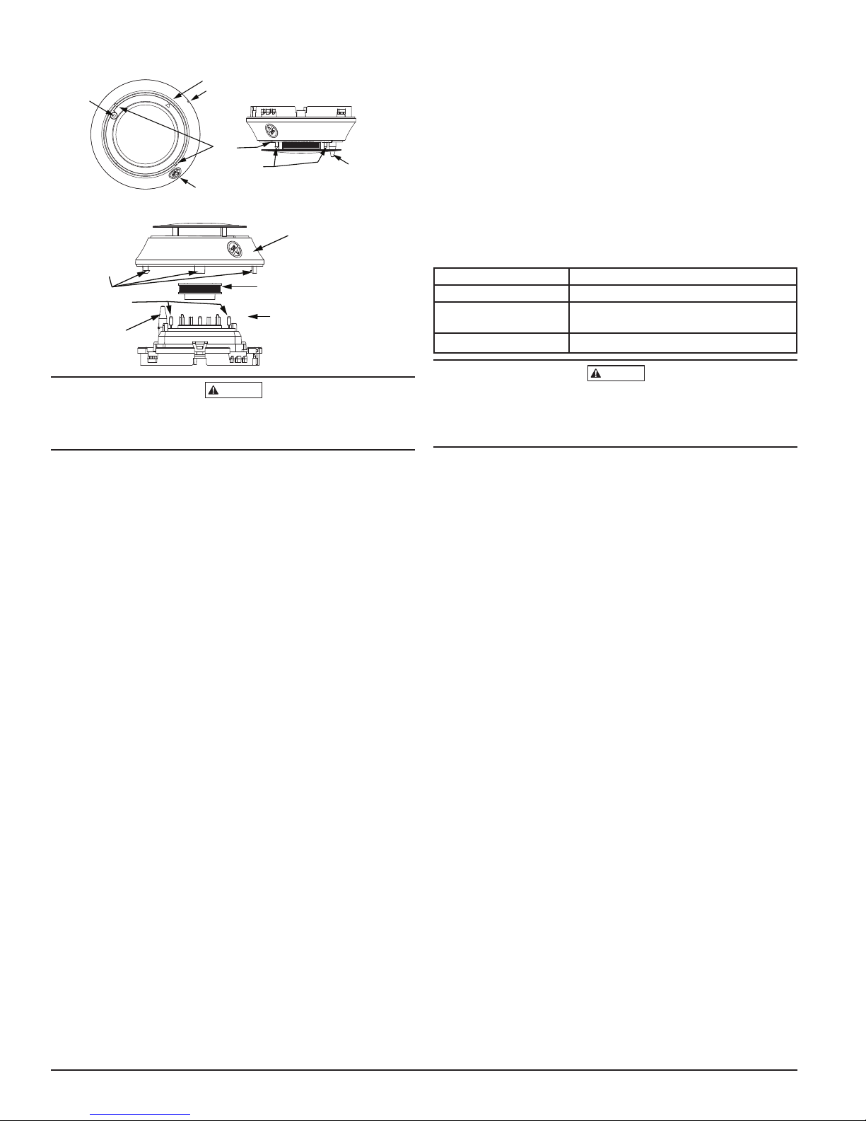
FIGURE 3. FEATURES OF THE FIRE/CO DETECTOR
CAUTION
CAUTION
CO Test Point
Infrared
Light
Pipe
Base Alignment Notch
LEDs
Thermistors
Magnet Test Point
Infrared
Light
Pipe
C2043-00
FIGURE 4. CLEANING THE FIRE/CO DETECTOR
Sensor Cover
Cover
Removal
Tabs
Sensing Chamber
Thermistors
Infrared
Light
Pipe
Cover and Screen
Sensing
}
Chamber
C2044-00
Dust covers provide limited protection against airborne dust particles during
shipping. Dust covers must be removed before the sensors can sense smoke.
Remove sensors prior to heavy remodeling or construction.
a. Put the device into test mode by holding a test magnet in the magnet
test area as shown in Figure 3 for 6-12 seconds.
NOTE: If the magnet is held in place for too long the fire alarm test func-
tion will be triggered. (See Magnet Test, above.) Reset the panel and
proceed with testing the smoke entry portion of the device.
b. Perform smoke entry testing immediately following the magnet test.
The magnet test initiates an approximately 10 minute period when the
detector’s signal processing software routines are not active.
Once in test mode, test the smoke detector using one of the tested and approved aerosol smoke products. Refer to the manufacturer’s published instructions for proper use of the canned smoke agent. When used properly, the
canned smoke agent will cause the smoke detector to go into alarm.
Tested and approved aerosol smoke products include:
Manufacturer Model
HSI Fire and Safety 25S, 30S (PURCHECK)
SDi SMOKE CENTURION , SOLOA10,
SMOKESABRE, TRUTEST, SOLO 365
No Climb TESTIFIRE 2000
Canned aerosol simulated smoke (canned smoke agent) formulas will vary
by manufacturer. Misuse or overuse of these products may have long term
adverse effects on the smoke detector. Consult the canned smoke agent manufacturer’s published instructions for any further warnings or caution statements.
TAMPER RESISTANCE
Model SK-FIRE-CO-W includes a tamper-resistant capability that prevents removal from the base without the use of a tool. Refer to the base manual for
details on making use of this capability.
TESTING
Before testing, notify the proper authorities that the system is undergoing
maintenance, and will temporarily be out of service. Disable the system to
prevent unwanted alarms.
All sensors must be tested after installation and periodically thereafter. Testing methods must satisfy the Authority Having Jurisdiction (AHJ). Sensors
offer maximum performance when tested and maintained in compliance with
NFPA 72. Sensitivity readings are available through the FACP. Refer to the
manufac turer’s published instructions for proper use.
The sensor can be tested in the following ways:
A. Functional: Magnet Test (P/N M02-04-01 or M02-09-00)
This sensor can be functionally tested with a test magnet. The test mag-
net electronically simulates smoke in the sensing chamber, testing the
sensor electronics and connections to the control panel.
a. Hold the test magnet in the magnet test area as shown in Figure 3.
b. The sensor should alarm the panel.
Two LEDs on the sensor are controlled by the panel to indicate sensor
status. Coded signals, transmitted from the panel, can cause the LEDs
to blink, latch on, or latch off. Refer to the control panel technical documentation for sensor LED status operation and expected delay to alarm.
NOTE: The magnet test initiates an approximately 10 minute period
when the detector's signal processing software routines are not active.
B. Smoke Entry
Canned aerosol simulated smoke (canned smoke agent) may be used for
smoke entry testing of the smoke detector.
The multi-criteria CO and smoke sensor uses algorithms to process sig-
nals received from multiple sensors to determine alarm conditions and
reduce false alarms. Therefore, a single burst of canned smoke will not
immediately place the detector into an alarm condition because the detector algorithms correctly determine a burst of canned smoke is not fire.
In order to perform functional testing of the photoelectric sensor, the
device must be placed into test mode. Test mode allows the detector to
isolate the individual sensors for testing. The device can be placed into
test mode through either of the following methods.
C. Direct Heat Method (Hair Dryer of 1000-1500 watts)
A hair dryer of 1000-1500 watts should be used to test the thermistors.
Direct the heat toward the thermistor, holding the heat source approximately 12 inches (30 cm) from the detector in order to avoid damaging
the plastic housing. The detector will reset only after it has had sufficient
time to cool. Make sure both thermistors are tested individually.
D. Multi-Criteria Testing
Testifire® by SDi provides testing of the smoke, heat and CO sensors. Consult
the manufacturer’s published instructions for complete usage instructions.
A sensor that fails any of these tests may need to be cleaned as described
under CLEANING, and retested. When testing is complete, restore the system
to normal operation and notify the proper authorities that the system is back
in operation.
E. Functional Gas Test
NOTE: Check with local codes and the AHJ to determine whether or not
a functional gas test is desired for an installation.
A canned CO testing agent may be used to verify the detector’s ability to
sense CO. Carbon Monoxide alarm thresholds are designed around CO
concentrations over time, as defined in UL standard 2034. Therefore, a
single burst of CO test agent will not immediately place the detector into
an alarm condition. In order to perform functional testing of the CO sensor, the device must be placed into test mode. Test mode eliminates the
time and concentration requirements needed for alarm and allows the
CO sensor to be tested. The device can be placed into test mode through
either of the following methods.
a. Put the device into test mode by holding a test magnet in the magnet
test area as shown in Figure 3 for 6-12 seconds.
NOTE: If the magnet is held in place for too long the fire alarm test func-
tion will be triggered. Reset the panel and proceed with testing the CO
portion of the device.
b. Perform functional gas entry testing immediately following the magnet
test. The magnet test initiates an approximately 10 minute period when
the detector's signal processing software routines are not active.
Once in test mode, test the CO sensor using a tested and approved
canned CO testing agent. A tested and approved canned CO testing agent
is Solo detector testers model C6 CO Detector Tester available from SDi.
Complete the CO sensor testing as follows:
Spray a UL approved CO agent into the top of the detector near the CO
sensor opening for at least 1 second. CO sensor opening is indicated by
2 I56-6602-000
2/21/2019
 Loading...