

Honeywell SK-Beam-T Installation And Maintenance Instructions Manual

INSTALLATION AND MAINTENANCE INSTRUCTIONS
SK-Beam, SK-Beam-T
I56-3433-004
Single-ended Reected Type
Projected Beam Smoke Detector
SPECIFICATIONS
GENERAL
Range: 16 to 230 Feet (5 to 70 m); 230 to 328 Feet (70 to 100 m) using optional accessory BEAMLRK
Sensitivity: 25% to 50% Total Obscuration in 6 levels
Level 1 = 25%
Level 2 = 30%
Level 3 = 40%
Level 4 = 50%
Level 5 = 30% to 50% (Acclimate)
Level 6 = 40% to 50% (Acclimate)
Spacing: 30 to 60 Feet (9.1 to 18.3 m)
Response Time: ALARM - 20 seconds typical
TROUBLE - 30 seconds typical
Trouble Conditions: Beam Blockage (96% or More Obscuration)
Improper Initial Alignment
Self-compensation limit reached (service needed)
In Alignment mode
Test/Reset Features: Integral Sensitivity Test Filter (SK-Beam-T only, requires additional external power supply)
Sensitivity Filter (Incremental scale on reflector)
Local Alarm Test Switch
Local Alarm Reset Switch
Remote Test and Reset Switch Capability (compatible with RTS451/RTS451KEY/RTS151/RTS151KEY)
Indicators: ALARM - Remote Output, Local LED (red)
TROUBLE - Remote Output, Local LED (yellow) Blink Pattern Indicates Trouble Diagnostics
NORMAL OPERATION - Local LED (flashing green with communication)
ALIGNMENT AIDS - Optical Gunsight (coarse adjustment) 00 to 99 Digital Display (fine adjustment)
SENSITIVITY - Digital Display Readout in Percent Obscuration
Style 7 Operation: On-board isolators provide style 7 operation. (may be disabled via shunts on circuit board)
12 Clintonville Road, Northford, CT 06472-1610
Phone: 203-484-7161 Fax: 203-484-7118
www.silentknight.com
ENVIRONMENTAL
Temperature: –22°F to 131°F (–30°C to 55°C);
NOTE: for applications below 32°F (0°C) see Special Applications section of this manual.
Humidity: 10% to 93% RH Noncondensing
Mechanical
Shipping Weight: 3.9 lbs. (1.77 kg)
Shipping Size: 15˝ × 10.5˝ × 6.5˝ (381 mm × 267 mm × 165 mm)
Mounting: Wall only without optional accessories
Wiring: Plug-in Terminal Blocks (12 to 22 AWG)
Adjustment Angle: ±10° Horizontal and Vertical
Paintable Trim Ring: May be painted using enamel or acrylic type paints
Electrical
Voltage: 15 to 32 VDC
Standby Current: Avg. Standby: 2 mA Max. (1 communication every 5 sec., LED flashing, SLC @ 24 V)
Max. Alarm (LED on): 8.5 mA Max.
Max. Trouble (LED on): 4.5 mA Max.
Max. Alignment: 20 mA Max.
External Supply (SK-Beam-T only): VO LTAG E - 15 to 32 VDC
CURRENT - 0.5 A Max.
Remote Output: (alarm) VOLTAGE - 15 to 32 VDC; NOTE: Output voltage same as device input voltage.
CURRENT - 15 mA maximum; 6 mA minimum; NOTE: Output current is limited by 2.2 kΩ resistor.
GENERAL DESCRIPTION
Model SK-Beam/SK-Beam-T is a long range projected beam smoke detector
designed to provide open area protection. It is to be used with UL-listed compatible control panels only. The detector consists of a transmitter/receiver unit
and a reflector. Smoke entering the area between the transmitter/receiver and
reflector causes a reduction in signal. When the obscuration reaches alarm
thresholds (chosen at the transmitter/receiver unit), the detector generates
an alarm signal. Complete blockage of the beam causes a trouble signal. Slow
changes in obscuration due to a build up of dirt or dust on the lens of the
detector are compensated for by a microcontroller that continuously monitors
the signal strength and periodically updates the alarm and trouble thresholds. When the self-compensation circuit reaches its limit, the detector generates a trouble signal, indicating the need for service.
Three LEDs on the detector indicate the current status: a red LED for alarm,
a yellow LED for trouble, and a blinking green LED for standby operation.
Note: The panel controls the status of the red and green LEDs. The local
reset button is accessible by removing the outer paintable trim ring. The
yellow LED will blink in specific patterns to provide a diagnostic aid when
diagnosing the cause of a trouble signal. It will also blink the amount of drift
compensation that has been used at the conclusion of the test. Trouble sig-
1 I56-3433-004
04-12
nals automatically reset upon removing the cause of trouble. Red and yellow
TERMINAL BLOCK
ISOLATOR
SHUNT
PAINTABLE TRIM RING
LEDs can be remotely connected to the remote Alarm and Trouble outputs.
These outputs mimic the functions of the detector’s red and yellow LEDs.
In addition to these indicators, there is a dual digital display that reads 00 to
99. This display is used to indicate the signal strength of the beam in alignment mode and to indicate the sensitivity setting of the detector in percent
obscuration when setting the sensitivity of the detector. No additional equipment is needed for alignment of the beam.
SPECIAL APPLICATIONS
Due to the inherent capabilities of projected type beam detectors they are
often installed in locations where spot-type detection is impractical. Projected
type beam smoke detectors are ideally suited for environmental conditions
that might include high ceilings, dusty and dirty environments, or environments that experience temperature extremes. Often these conditions present
special problems for the installation of spot-type detectors and even greater
problems for their proper maintenance. Due to the inherent flexibility of
mounting locations and large coverage area of projected type beam detectors
often the conditions above can be addressed or minimized.
Some examples of applications for beam detectors might include freezers, aircraft hangars, cold storage warehouses, shipping warehouses, enclosed parking facilities, sporting arenas and stadiums, concert halls, barns, or stables.
Some of these environments might be considered too hostile for spot-type
smoke detectors. If the environment is considered to be hostile then the colder
alarm threshold settings should be used.
Before installing the transmitter/receiver unit or reflector in these types of
applications special consideration should be given to insure proper operation
of the beam detector. The beam detector should not be installed in environments where heavy condensation or icing is likely. Condensation or icing of
the reflector surface or the outer surface of the transmitter/receiver unit will
obscure the light beam resulting in a false alarm. If elevated humidity levels
and rapidly changing temperatures can be expected then condensation will
likely form and the application should not be considered acceptable for the
beam detector.
APPROVED ACCESSORIES
The following accessories can be purchased separately for use with this beam
detector.
BEAMLRK
The BEAMLRK allows reflected beam detectors to be installed at separations
between 230 and 328 feet (70 to 100 meters). At these distances, four 8˝ ×
8˝ reflectors must be used to provide enough reflected infrared light. This
kit includes 3 additional reflectors with new test scale legends. The reflector
included with the transmitter/receiver unit is the fourth reflector to be used.
This kit is not compatible with the multi-mount kit (BEAMMMK).
BEAMMMK
The BEAMMMK allows reflected beam detectors and reflectors to be mounted
to either a vertical wall or the ceiling. The kit allows for additional alignment
range in cases where the detector and reflector cannot be mounted within
10° of each other. The kit includes the hardware necessary to mount either
a single transmitter/receiver unit or a single reflector. (To mount the transmitter/receiver the surface mount kit, BEAMSMK, must also be used). If the
transmitter/receiver and the reflector require additional alignment range two
kits are required. The kit is not compatible with the long-range reflector kit
(BEAMLRK).
BEAMSMK
The BEAMSMK allows reflected beam detectors to be mounted when surface
wiring is used. This kit must be used when mounting the transmitter/receiver
unit with the multi-mount kit (BEAMMMK).
6500-MMK
The 6500-MMK provides a heavy-duty multi-mount bracket for installations
prone to building movement or vibration. It offers similar tilt and swivel flexibility found on the BEAMMMK. (To mount the transmitter/receiver to the
6500-MMK, the surface mount kit, 6500-SMK, must be used).
6500-SMK
The 6500-SMK allows the transmitter/receiver to be mounted to the 6500MMK heavy duty multi-mount kit.
2 I56-3433-004
04-12
BEAMHK
The BEAMHK allows the transmitter/receiver unit to operate in environments
prone to the formation of condensation. Condensation forming on the beam
detector unit may result in trouble or false alarm conditions. BEAMHK will
lessen the likelihood of condensation by maintaining the unit at a temperature
that is slightly higher than the surrounding air. Please refer to the BEAMHK
installation manual for operation instructions.
BEAMHKR
The BEAMHKR allows the reflector to operate in environments prone to the
formation of condensation. Condensation forming on the reflector may result in trouble or false alarm conditions. BEAMHKR will lessen the likelihood
of condensation by maintaining the reflector at a temperature that is slightly
higher than surrounding air. The kit requires a 24V power supply. When used
with the long-range reflector kit (BEAMLRK), it is necessary to purchase and
install four BEAMHKR kits. Please refer to the BEAMHKR installation manual
for operation instructions.
RTS451/RTS451KEY/RTS151/RTS151KEY
The remote test accessory, RTS451/RTS451KEY or RTS151/RTS151KEY, allows
for the beam detector to be tested remotely. The test accessory provides test and
reset functions and green and red LED’s that mimic the LEDs on the detector.
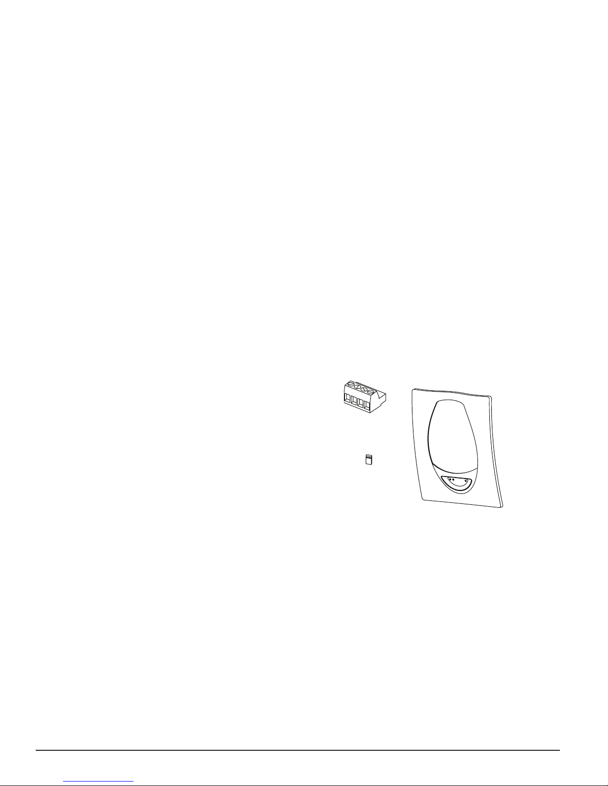
PARTS LIST
Description Quantity
Transmitter/Receiver Unit .....................................1
Paintable Trim Ring .........................................1
Reflector ..............................................1
Plug-in Terminal Blocks ......................................3
Isolator Shunts ............................................2
Instruction Manual .........................................1
Orange Paper Sheet .........................................1
PARTS DIAGRAM (NOT TO SCALE)
C0306-00
DETECTOR PLACEMENT
This section of the manual discusses the placement of projected beam detectors. Though this information is based upon industry expertise, it is intended
to be used only as a technical guide. Always comply with the requirements of
applicable codes and standards such as, NFPA 72, National Fire Alarm Code,
as well as directives of the Authority Having Jurisdiction (AHJ).
Projected beam detectors are usually located with their beams parallel to the
ceiling. However, they can be mounted vertically or at any angle to protect the
area involved. Since beam detectors sense the smoke buildup over a distance,
they are ideal for locations with high ceilings. They can also be mounted on a
wall or ceiling below the level of a spot type detector, reducing the effects of
air stratification. Some typical locations would include large areas with high
ceilings such as atriums, warehouses, and factories.
NOTE: Projected beam smoke detectors should always be mounted to stable mounting surfaces. See the MOUNTING LOCATION section for details.
Some fire codes specify spacing on a given center-to-center distance between
detectors under ideal conditions. This spacing is based on rooms with smooth
ceilings and no physical obstructions between the contents being protected
and the detectors. Moreover, they are also based on a maximum ceiling height,
and on the assumption that the value and the combustible nature of the contents of the room being protected do not warrant greater protection or closer
spacing.
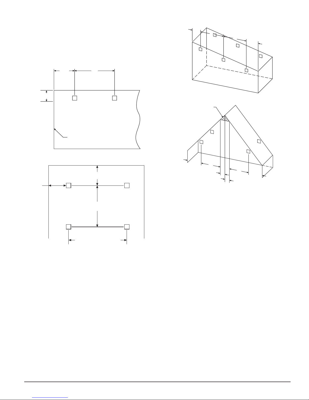
In a room with a smooth ceiling, detectors should be spaced between 30 and
MAX.
MOUNT SPOT DETECTOR
60 feet (9.1 to 18.3 m). One-half that spacing between the beam and the sidewall may be used as a guide. See Figure 1. The beam detector can be mounted
with the transmitter/receiver on one wall and the reflector on the opposite
wall, or both suspended from the ceiling, or any wall/ceiling combination.
In the case of the ceiling mount, the distance from the end walls should not
exceed one-quarter of the selected spacing (7.5 ft. [2.3 m] maximum if the
spacing is 30 ft. [9.1 m] ). See Figure 2.
FIGURE 1. SPACING FOR SMOOTH CEILING (SIDE VIEW):
1
/2 S S
FIGURE 3. SLOPED CEILING (SHED TYPE):
3 FT.
(0.9M)MAX.
S
REFLECTOR
Tx/Rx
S
1
2
/
S MAX.
12 - 18 IN.
(0.3 - 0.46M)
WALL
FIGURE 2. SPACING FOR SMOOTH CEILING (TOP VIEW):
1
/2 S MAXIMUM
Tx/Rx REFLECTOR
1
/4 S
S
Tx/Rx REFLECTOR
16 FT. (5M) MINIMUM
328 FT. (100M) MAXIMUM
In the case of peaked or sloped ceilings, codes may specify spacing of detectors by using horizontal spacing from the peak of the roof or ceiling. Figures
3 and 4 show the spacing for both the shed type and peaked type sloped
ceilings.
On smooth ceilings, beam smoke detectors should generally be mounted between 12 and 18 inches (0.3 to 0.46 m) from the ceiling. In many cases, however, the location and sensitivity of the detectors shall be the result of an
engineering evaluation that includes the following: structural features, size
and shape of the room and bays, occupancy and uses of the area, ceiling
height, ceiling shape, surface and obstructions, ventilation, ambient environment, burning characteristics of the combustible materials present, and the
configuration of the contents in the area to be protected. As a general rule,
reflective objects such as ductwork or windows should be a minimum of 15
inches (38.1 cm) from the path of the beam.
C0254-00
C0255-00
C0256-00
FIGURE 4. SLOPED CEILING (PEAKED TYPE):
ANYWHERE IN THIS
AREA AT LEAST 4 IN. (100 mm)
VERTICALLY FROM PEAK
REFLECTOR
Tx/Rx
1
2
/
S S
3 FT. (0.9M)
MAX.
S
3 FT. (0.9M)
MAX.
1
2
/
S
C0257-04
MOUNTING LOCATIONS
Beam detectors require a stable mounting surface for proper operation. A surface that moves, shifts, vibrates, or warps over time will cause false alarm or
trouble conditions. Initial selection of a proper mounting surface will eliminate false alarms and nuisance trouble signals.
Mount the detector on a stable mounting surface, such as brick, concrete,
a sturdy load-bearing wall, support column, structural beam, or other surface that is not expected to experience vibration or movement over time. DO
NOT MOUNT the beam detector on corrugated metal walls, sheet metal walls,
external building sheathing, external siding, suspended ceilings, steel web
trusses, rafters, nonstructural beam, joists, or other such surfaces.
In cases where only one stable mounting surface as defined above can be
used, the transmitter/receiver unit should be mounted to the stable surface
and the reflector should be mounted to the less stable surface. The reflector has a much greater tolerance for the unstable mounting locations defined
above.
MOUNTING INSTRUCTIONS
The transmitter/receiver unit may be mounted over a recessed junction box.
The cavity behind the detector is then used for routing of the wiring from the
junction box to the terminal blocks on the detector. The transmitter/receiver
unit should be mounted to the wall such that unit covers the recessed junction box in the wall completely. If the junction box is not recessed then you
may use the surface mount kit (BEAMSMK). See the BEAMSMK installation
instructions for surface mounting instructions. The transmitter/receiver unit
can be mounted to the wall using the supplied drilling template (see Appendix
II). The detector base has 4 primary mounting keyholes, one in each corner of
the base. All four hole locations should be used to provide a secure mounting.
The outer housing of the beam detector is held to the base using four screws.
In order to mount the detector you must remove the outer housing first.
The reflector can be mounted to the wall using the supplied drilling template
(see Appendix III). The reflector has 4 mounting holes, one in each corner.
All four hole locations should be used to provide a secure mounting. The
reflector must be mounted such that it is within 10° in both the X and Y
planes of the transmitter/receiver unit. See Figure 5a. The reflector must also
be mounted such that the plane of the reflector is perpendicular to the optical
3 I56-3433-004
04-12
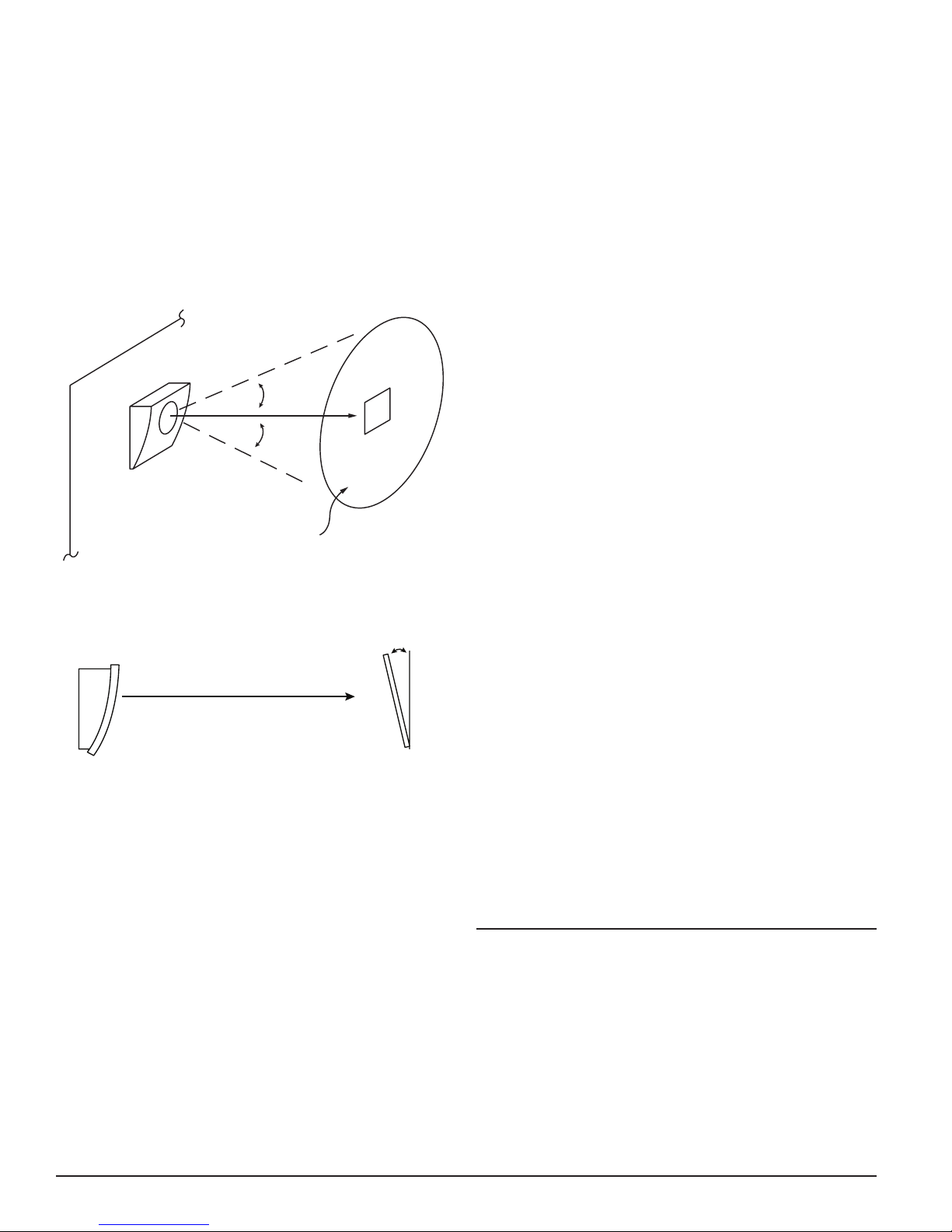
line of sight to the transmitter/receiver unit. The maximum tolerance for nonperpendicular mounting locations is 10°. See Figure 5b. If the reflector cannot
be mounted within 10° of the transmitter/receiver unit then the multi-mount
kit (BEAMMMK) or the heavy-duty multi-mount kit (6500-MMK) may be used
to provide greater angular adjustment of the transmitter/receiver unit. If the
perpendicular plane of the reflector cannot be mounted within 10° of the optical line of sight then the multi-mount kit can be used for the reflector. See
BEAMMMK or 6500-MMK instructions.
To aid in locating the reflector in the alignment mirror at long distances an
orange, adhesive-backed sheet of paper is provided. Remove the protective
backing from the orange paper. Temporarily affix the orange paper next to the
reflector. The location of the paper is not critical. It may be placed anywhere
near the reflector as long as it not covering the reflective surface of the reflector. This paper should be removed once the installation is completed.
FIGURE 5A. REFLECTOR MOUNTING GUIDELINES
X
WALL
Y
10°
10°
REFLECTOR
ACCEPTABLE MOUNTING
LOCATIONS FOR REFLECTOR
C0258-01
FIGURE 5B. REFLECTOR MOUNTING GUIDELINES
10° MAXIMUM
OPTICAL LINE OF SIGHT
REFLECTOR
C0259-00
MOUNTING CONSIDERATIONS FOR SINGLE ENDED BEAM DETECTORS
There must be a permanent clear line of vision between the detector and the
reflector. Reflective objects must not be near the line of vision between the
detector and reflector. Reflective objects too near to the line of sight can reflect
the light beam from the transmitter to the receiver. If this occurs, the detector
will not be able to distinguish these reflections from those of the reflector and
the protected space will be compromised. Reflective objects such as ductwork
or windows should be a minimum of 15 inches (38.1 cm) from the path of the
beam. In cases where reflective objects cannot be avoided, the complete reflector blockage test can be used to determine if the installation is acceptable.
See Testing and Maintenance Section of this manual.
Light sources of extreme intensity such as sunlight and halogen lamps, if directed at the receiver, can cause a dramatic signal change resulting in fault
and alarm signals. To prevent this problem direct sunlight into the transmitter/receiver unit should be avoided. There should be a minimum of 10°
between the pathway of the light source and detector and the line of sight
between detector and reflector.
Operation of the detector through panes of glass should be avoided. Since
single ended beam detectors operate on a reflection principle, a pane of glass
perpendicular to the line of sight between the detector and the reflector can
reflect the light beam from the transmitter to the receiver. If this occurs, the
detector will not be able to distinguish these reflections from those of the reflector and the protected space will be compromised.
Panes of glass will also absorb some of the light as it passes through it. This
absorption of light will reduce the acceptable installed distance between the
detector and the reflector.
In cases where operation through panes of glass cannot be avoided some specific installation practices can help to minimize the effects of the glass. These
practices include: avoid penetration of multiple panes of glass, position the
glass so that it is not perpendicular to the line of sight between the detector
and the reflector, (A minimum of 10° off perpendicular should be considered),
and make certain that the glass is smooth, clear and mounted securely. The
complete reflector blockage test can be used to determine if the installation is
acceptable. See Testing and Maintenance Section of this manual.
Where high ceilings (in excess of 30 feet or 9.1 meters) are present additional
beams may be required to detect smoke at lower levels.
WIRING INSTALLATION GUIDELINES
Always install all wiring in compliance with the National Electrical Code, and/
or the applicable local codes, and any special requirements of the local authority having jurisdiction. Proper wire gauges and suitable means for strain
relief should be used. The conductors used to connect beam smoke detectors
to control panels and accessory devices should be color-coded to reduce the
likelihood of wiring errors. Improper connections can prevent a system from
responding properly in the event of a fire.
Installation wire used for the beam detector shall be no smaller than 22 AWG
(1.0 mm2). For best system performance, all wiring should be twisted pair and
installed in separate grounded conduit. Do NOT mix fire system wiring in the
same conduit as any other electrical wiring. Shielded cable may be used to
provide additional protection against electrical interference.
When installing the beam smoke detector in applications where the head
unit will be mounted to either a wall or the ceiling using the multi-mount kit
(BEAMMMK) or 6500-SMK flexible conduit will be used. The surface mount
kit (BEAMSMK) or 6500-SMK and multi-mount kit (BEAMMMK) or 6500-SMK
must be installed with the cable before wiring the unit, according to the instructions supplied with the kit.
When the detector has been mounted over a recessed junction box, all wiring
should be routed out of the box and behind the detector to the bottom of the
detector where the terminal blocks are located. When installing the wiring
in the junction box be sure to leave enough wire in the box to connect to the
terminal blocks. (Approximately 9˝ (23 cm) of wire outside of the junction box
will be required for proper installation). All wiring to the detector is done via
pluggable terminal blocks. In order to properly make electrical connections
strip approximately 1/4˝ (6 mm) of insulation from the end of the wire, sliding
the bare end of the wire under the clamping plate screw.
Figure 6 shows all the wiring connections to the transmitter/receiver unit.
Figure 7 shows the proper wiring diagram for either Class A or Class B operation. Figure 8 shows the connections that are necessary when using one of
the optional remote test stations (RTS451/RTS151 or RTS451KEY/RTS151KEY).
Figure 9 shows the remote output for alarm indication.
WARNING: Disable the zone or system before applying power to the beam
detector to prevent unwanted alarms. When applying power to
the beam detector before the alignment procedure has been completed the detector may enter alarm or fault.
4 I56-3433-004
04-12
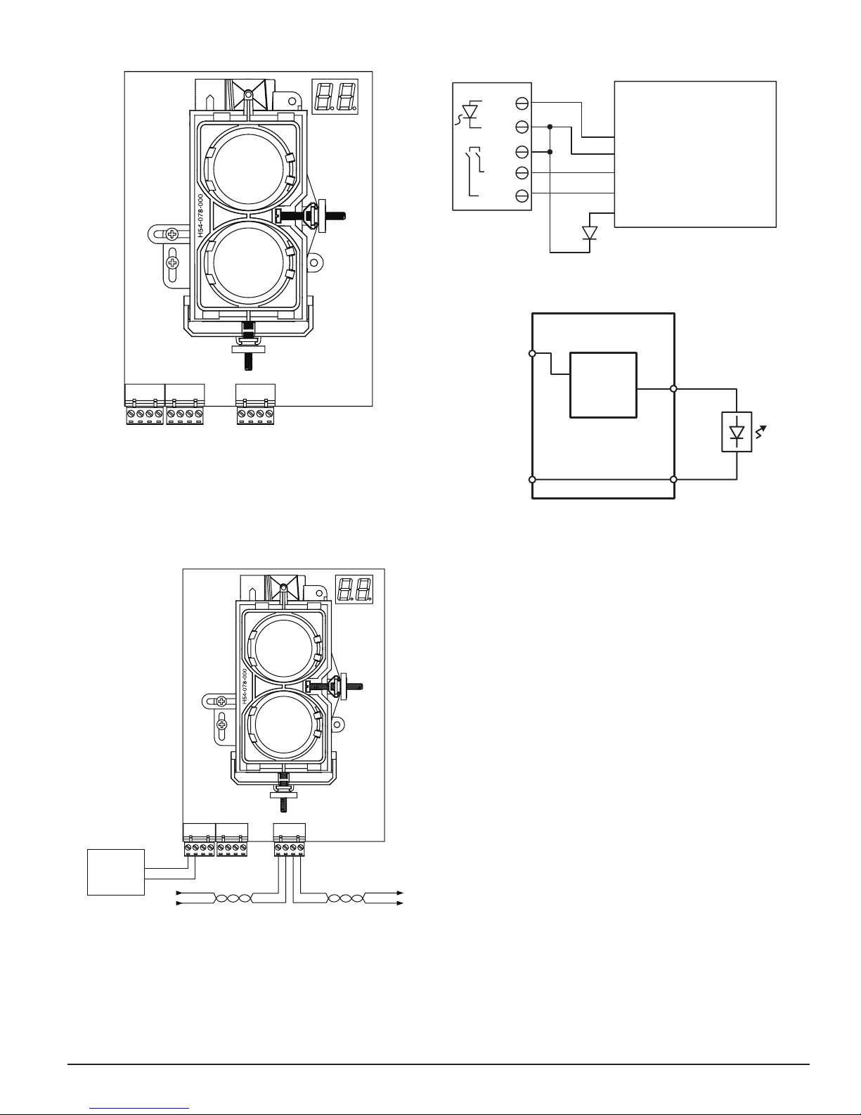
FIGURE 6. WIRING CONNECTIONS AT DETECTOR
TROUBLE OUT
T
DETECTOR
manual for cir cuit output ratings.
FIGURE 8. WIRING DIAGRAM (RTS451/RTS151)
T3 T2 T1
RESET I NPUT
TEST INPUT
AUX (–)
REMOTE ALARM OUT
NOT USED
REMOTE
TEST OPTION (–)
TEST OPTION (+)
SLC (–)
SLC (+)
SLC (–)
SLC (+)
C0260-01
PIN 1
PIN 2
PIN 4
PIN 3
PIN 5
RTS451/RTS451KEY
or RTS151/RTS151KEY
SLC IN +T1-1
T1-2
T2-1
REMOTE ALARM OUT
T2-2
AUX (–)
T2-4
RESET INPUT
T2-3
TEST INPUT
T3-3
REMOTE TROUBLE OUTPUT
OPTIONAL YELLOW LED
FIGURE 9. WIRING DIAGRAM (RTS451/RTS151)
BDT-SS
SLC (+)
Alarm
Signal
Circuit
(Note 1)
SLC ( –)
Note 1: See electrical ratings section of this
T2-1
T2-2
SLC OUT +
SLC OUT –
Red
T1-3
T1-4SLC IN –
C0328-06
C0369-00
FIGURE 7. WIRING DIAGRAM
T3 T2 T1
LISTED
REMOTE
POWER
SOURCE
* Only used for
SK-BEAM-T. See
electrical ratings.
+
ñ
FROM PANEL OR
PREVIOUS DEVICE
COMMUNICATION LINE
+ñ+ñ+
ñ
32 VDC MAX.
TWISTED PAIR IS
RECOMMENDED.
TO NEX
DEVICE
C0335-03
INSTALLATION / ALIGNMENT
Reference Figures 10 through 14 for installation, alignment, and maintenance.
Please make sure to complete all steps in order to ensure a successful installation. Proper application, mounting, alignment, and set-up will minimize false
alarms and nuisance trouble signals.
PRE-ALIGNMENT CHECKLIST
• Insure that both the detector and reflector are mounted securely to stable
surfaces.
• Insure that all wiring is correct.
• Insure that terminal blocks are fully seated into their receptacles on the
detector.
• Complete any wiring dressing to minimize movement to the detector once
the alignment procedure is completed.
• Insure that the appropriate number of reflectors are used for the installed
distance. Distances between 230 and 328 Feet (70 – 100 m) require additional reflectors (4 total). The BEAMLRK accessory should be used in
these cases.
• Insure that the line of sight between the detector and reflector is clear
and that reflective objects are not too near. See Mounting Instructions
for more details.
• Insure that both the detector and reflector are mounted within their
ñ
+
operational parameters for off axis angles. See Mounting Instructions
for more details.
• Disable the zone or system to prevent unwanted alarms before applying
power.
• Insure power to the detector is “ON”.
• Insure that the appropriate address is set on the code wheels.
You are now ready to begin the alignment procedure.
5 I56-3433-004
04-12
 Loading...