

Honeywell Silent Knight IDP-Monitor Installation And Maintenance Instructions Manual
INSTALLATION AND MAINTENANCE
0
1
2
3
4
9
8
7
6
5
0
TENS
O
NES
ADDRESS
LOOP
9
8
7
6
5
4
3
2
1
0
9
8
7
6
5
4
3
2
1
0
1
2
3
4
8
7
6
5
9
O
N
E
S
A
D
D
R
E
S
S
TE
N
S
1
0
2
3
4
5
6
7
8
9
1
0
2
3
4
5
6
7
8
9
9
8
7
6
5
4
3
2
1
0
0
1
2
3
4
5
6
7
8
9
TENS
ONES
ADDRESS
LOOP
1
0
7
8
6
5
4
3
2
9
INSTRUCTIONS
IDP-Monitor Module
Specifications
Normal Operating Voltage: 15 to 32 VDC
Maximum Current Draw: 5.0 mA (LED on)
Average Operating Current: 375µA (LED flashing)
EOL Resistance: 47K Ohms
Maximum IDC
wiring resistance: 1,500 Ohms
Temperature Range: 32°F to 120°F (0°C to 49°C)
Humidity: 10% to 93% Non-condensing
Dimensions: 4
(Mounts to a 4˝ square by
21⁄8˝ deep box.)
Accessories: SMB500 Electrical Box
1
⁄2˝ H x 4˝ W x 11⁄4˝ D
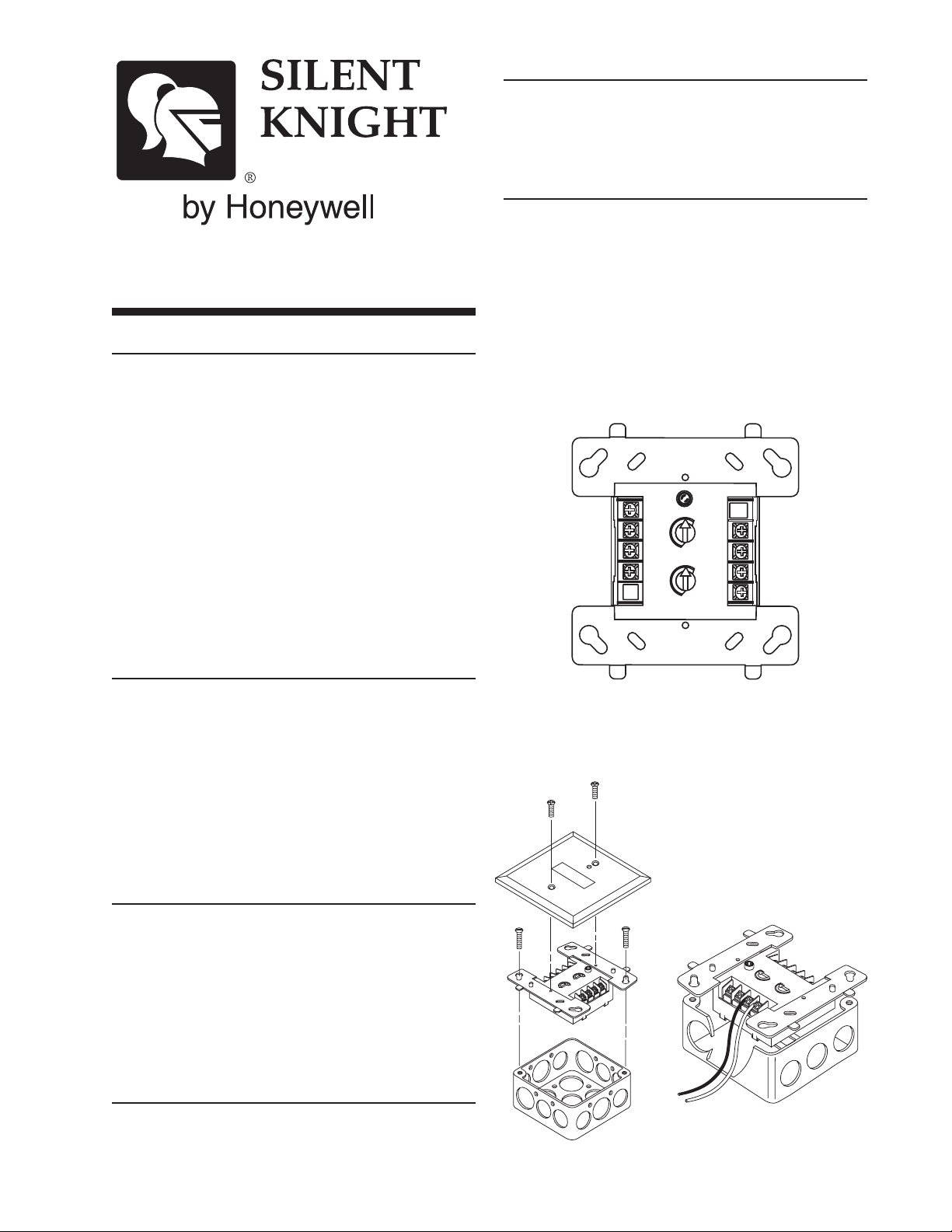
Mounting
The IDP-Monitor mounts directly to 4˝ square electrical boxes (see Figure 2A). The box must have a minimum depth of 21⁄8˝. Surface mounted electrical boxes
(SMB500) are available from Silent Knight.
Wiring
NOTE: All wiring must conform to applicable local
codes, ordinances, and regulations. This module is intended for power limited wiring only.
1. Install module wiring in accordance with the job drawings and appropriate wiring diagrams.
2. Set the address on the module per job drawings.
3. Secure module to electrical box (supplied by installer),
as shown in Figure 2A.
Figure 1. Controls and Indicators:
Before Installing
C0218-01
This information is included as a quick reference installation guide. Refer to the control panel installation manual
for detailed system information. If the modules will be
installed in an existing operational system, inform the
NOTE: For UL Listed security installations, the IDP-Monitor
must be mounted within the control panel enclosure.
Figure 2A. Module mounting:
operator and local authority that the system will be temporarily out of service. Disconnect power to the control
panel before installing the modules.
NOTICE: This manual should be left with the owner/
user of this equipment.
General Description
Figure 2B:
The IDP-Monitor Module is intended for use in intelligent, two-wire systems, where the individual address of
each module is selected using the built-in rotary switches.
It provides either a Class A or Class B fault tolerant initiating device circuit (IDC) for normally open contact fire
alarm and supervisory devices, or either normally open or
normally closed security devices. The module has a panel
controlled LED indicator.
Compatibility Requirements
To ensure proper operation, this module shall be connected to a compatible Silent Knight system control panel
(list available from Silent Knight).
C0157-00
C0156-00
K200-08-00 1 I56-2724-002
9
8
7
6
5
4
3
2
1
0
0
1
2
3
4
5
6
7
8
9
TENS
ONES
ADDRESS
LOOP
0
7
8
6
5
4
3
2
1
9
FROM P
ANEL
OR
(+)
(–)
TO
NEXT
(+)
(–)
DEVICE
(+
)
(–)
MONI
TO
R
CONNECT
MODULES
TO
LISTED COMP
AT
IBLE
32 VDC MAX.
SHIELDED-TWISTED
P
AI
R
IS RECOMM
ENDE
D
SILENT
KNIGHT
CONT
ROL
P
ANELS ONL
Y
PREVIOUS DEV
IC
E
ALL
WIRING SHOWN IS SUPE
R
VISED
AND POWER LIMITE
D
COMMUNICA
TION LOSS (OPTIONA
L
CONNECTION FOR
PA
NELS WHICH SUPPOR
T
THIS FEA
TURE)
47 K EOL
RESIST
OR
ELR-47K
ANY
NUMBER OF UL
LISTED CONT
ACT
CLOSURE
DEVICES MA
Y
BE USED. DO NOT
MIX FIRE
ALARM INITIA
TING, SUPER
VISOR
Y
, OR
SECURITY
DEVICES ON
THE SAME MODULE.
INITIA
TING DEVICE CIRCUIT
(IDC) - NFP
A
STYLE
B
POWER LIMITED: 230A
MA
X @ 12 VDC MA
X
INST
ALL
CONT
ACT
CLOSURE DEVICES PER
MANUF
ACTURER'S
I
NST
ALLA
TION INSTRUCTIONS.
MODULE
14K SERIES RESISTOR
SIGNAL LINE CIRCUIT (SLC)
9
8
7
6
5
4
3
2
1
0
0
1
2
3
4
5
6
7
8
9
TENS
ONES
ADDRESS
LOOP
0
7
8
6
5
4
3
2
1
9
MODULE
FROM PANEL OR
(+)
(-)
TO NEXT
(+)
(–)
DEVICE
(+)
(–)
MONITOR
CONNECT MODULES TO LISTED COMPATIBLE
SILENT KNIGHT CONTROL PANELS ONLY
PREVIOUS DEVICE
ALL WIRING SHOWN IS SUPERVISED AND POWER LIMITED
EOL RESISTOR
IS INTERNAL AT
TERMINALS 8 & 9.
ANY NUMBER OF UL LISTED CONTACT CLOSURE
DEVICES MAY BE USED. DO NOT MIX FIRE
ALARM INITIATING, SUPERVISORY, OR
SECURITY DEVICES ON THE SAME MODULE.
INSTALL CONTACT CLOSURE DEVICES PER
MANUFACTURER'S INSTALLATION INSTRUCTIONS.
32 VDC MAX
SHIELDED-TWISTED PAIR
IS RECOMMENDED
COMMUNICATION LOSS (OPTIONAL CONNECTION
FOR PANELS WHICH SUPPORT THIS FEATURE)
SIGNAL LINE CIRCUIT (SLC)
9
8
7
6
5
4
3
2
1
0
0
1
2
3
4
5
6
7
8
9
TENS
ONES
ADDRESS
LOOP
0
7
8
6
5
4
3
2
1
9
(+)
(–)
(+)
(–)
(+
)
(–)
MONI
TO
R
ALL
WIRING SHOWN IS SUPE
RVISED
AND POWER LIMITE
D
COMMUNICA
TION LOSS (OPTIONA
L
CONNECTION FO
R
PA
NELS WHICH SUPPOR
T
THIS FEA
TURE)
47 K EOL
RESIST
OR
ELR-47K
ANY
NUMBER OF UL
LISTED CONT
ACT
CLOSURE
DEVICES MA
Y
BE USED. DO NOT
MIX FIRE
ALARM INITIA
TING, SUPER
VISOR
Y
, OR
SECURITY
DEVICES ON
THE SAME MODULE.
INITIA
TING DEVICE CIRCUIT
(IDC) - NFP
A
STYLE
B
POWER LIMITED: 230A
MA
X @ 12 VDC MA
X
INST
ALL
CONT
ACT
CLOSURE DEVICES PER
MANUF
ACTURER'S
I
NST
ALLA
TION INSTRUCTIONS.
MODUL
E
SIGNAL LINE CIRCUIT (SLC)
32 VDC MAX.
TWISTED PAIR
IS RECOMMENDED
FROM PANEL OR
PREVIOUS DEVICE
CONNECT MODULES TO LISTED COMPATIBLE
SILENT KNIGHT CONTROL PANELS ONLY
TO NEXT
DEVICE
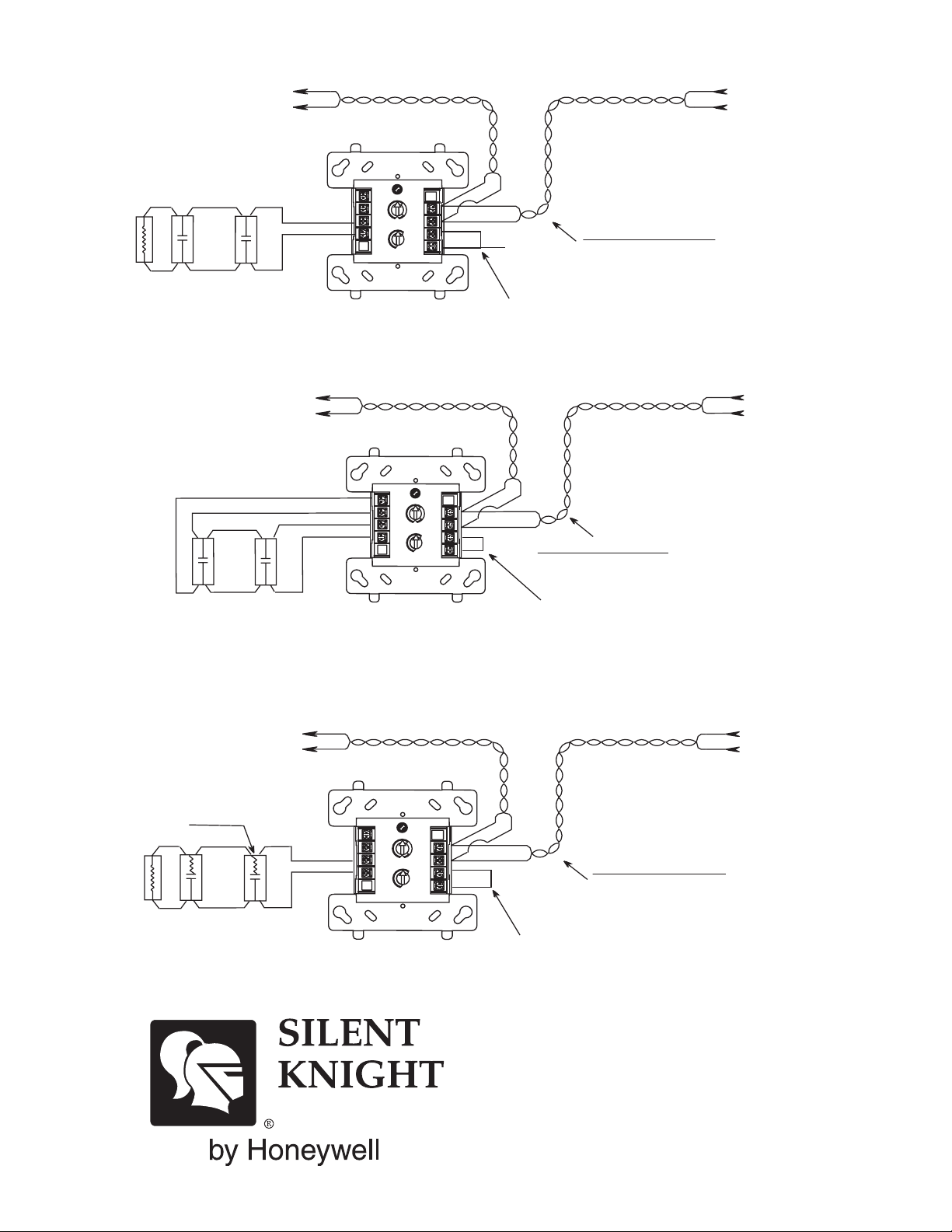
Figure 3. Typical 2-wire initiating circuit configuration, NFPA Style B:
Figure 4. Typical 4-wire fault tolerant initiating circuit configuration, NFPA Style D:
C0804-01
Figure 5. Typical 2-wire initiating circuit configuration for security systems (with alarm versus short capability):
NOTE: For UL Listed security installations, the IDP-Monitor must be mounted within the control panel enclosure.
K200-08-00 2 I56-2724-002
C0805-01
7550 Meridian Circle
Maple Grove, MN 55369-4927
763-493-6455; 800-328-0103
Fax: 763-493-6475
http://www.silentknight.com
© 2006 Silent Knight 8/05
C0806-01
 Loading...