

Honeywell SILEN KNIGHT IDP-Relay-6 Installation And Maintenance Instructions Manual

INSTALLATION AND
WARNING
MAINTENANCE INSTRUCTIONS
IDP-Relay-6
Six Relay Control Module
SPECIFICATIONS
Normal Operating Voltage: 15-32 VDC Stand-By
Current: 1.45 mA
Alarm Current: 32 mA (assumes all six relays
have been switched once and
all six LEDs solid on)
Temperature Range: 32°F to 120°F (0°C to 49°C)
Humidity: 10 to 85% Non-condensing
Dimensions: 6.8˝ H × 5.8˝ W × 1.0˝ D
Maximum IDC
Wiring Resistance: 40 ohms
Accessories: IDP-ACB cabinet and chassis
Wire Gauge: 12-18 AWG
Relay Current: 30 mA/Relay Pulse (15.6
mS pulse duration) pulse
under panel control
ground yourself with a proper wrist strap before handling
any circuits so that static charges are removed from the
body. The housing cabinet should be metallic and suitably grounded.
NOTICE: This manual should be left with the owner/
user of this equipment.
GENERAL DESCRIPTION
The IDP-Relay-6 Six Relay Control Module is intended
for use in an intelligent alarm system. Each module is
intended for Form-C switching applications, which do
not require wiring supervision for the load circuit. A
single isolated set of dry relay contacts is provided for
each module, which is capable of being wired for either
normally open or normally closed for each operation.
Each module has its own address. A pair of rotary code
switches is used to set the address of the first module
from 01 to 94. The remaining modules are automatically
assigned to the next five higher addresses. Provisions are
included for disabling a maximum of three unused modules to release the addresses to be used elsewhere. Each
IDP-Relay-6 module also has panel controlled green LED
indicators. The panel can cause the LEDs to blink, latch
on, or latch off.
Contents include:
(6) 1 × 3 Terminal Blocks
(1) 1 × 4 Terminal Blocks
(2) 11/4˝ (32mm) Stand offs
(4) Machine Screws
(2) Nuts
(1) Shunt (NOTE: For the disable position, not more
than one shunt shall be installed at the same time)
BEFORE INSTALLING
If the modules will be installed in an existing operational
system, inform the operator and local authority that the
COMPATIBILITY REQUIREMENTS
To ensure proper operation, this module shall be connected
to a compatible Silent Knight system control panel.
system will be temporarily out of service. Disconnect the
power to the control panel before installing the modules.
This system contains static sensitive components. Always
CURRENT RATING MAXIMUM VOLTAGE LOAD DESCRIPTION APPLICATION
3 A 30 VDC Resistive Non-coded
2 A 30 VDC Resistive Coded
.9 A 110 VDC Resistive Non-coded
.9 A 125 VDC Resistive Non-coded
.5 A 30 VDC Inductive (L/R=5ms) Coded
1 A 30 VDC Inductive (L/R=2ms) Coded
.3 A 125 VAC Inductive (PF=.35) Non-coded
1.5 A 25 VAC Inductive (PF = .35) Non-coded
.7 A 70.7 VAC Inductive (PF=.35) Non-coded
2 A 25 VAC Inductive (PF=.35) Non-coded
All relay switch contacts are shipped in the standby state (open) state, but may have transferred to the activated (closed)
state during shipping. To ensure that the switch contacts are in their correct state, modules must be made to communicate with the panel before connecting circuits controlled by the module.
K200-15-00 1 I56-2732-003
2
1
3
1
COMPONENTS
0
1
2
3
4
5
6
7
8
9
0
7
8
6
5
4
3
2
1
9
1
0
1
1
1
2
1
3
1
4
1
5
BASE
ADDRESS
ADDRESS
DISABLE
N
O
N
E
O
N
E
T
W
O
T
H
R
E
E
0
1
2
3
4
5
6
7
8
9
0
7
8
6
5
4
3
2
1
9
BASE
ADDRESS
ADDRESS
DISABLE
NONE
ONE
TW
O
THREE
Backbox
Mounting
Holes
The following is a description of the IDP-Relay-6 mounting framework:
• One or two IDP-Relay-6 modules can be installed in a
IDP-ACB cabinet
The IDP-ACB cabinet has a built-in chassis that will accommodate one or two IDP-Relay-6 modules.
C0234-03
Figure 1: IDP-ACB Cabinet
The front IDP-Relay-6 module positions of each chassis
are offset below the rear IDP-Relay-6 module positions
so that all of the status indicators are visible. For cabinet
dimensions refer to IDP-ACB instruction manual.
INSTALLATION STEPS
1. Cabinet Mounting
In a clean, dry area, mount the backbox using the four
holes provided in the back surface of the cabinet.
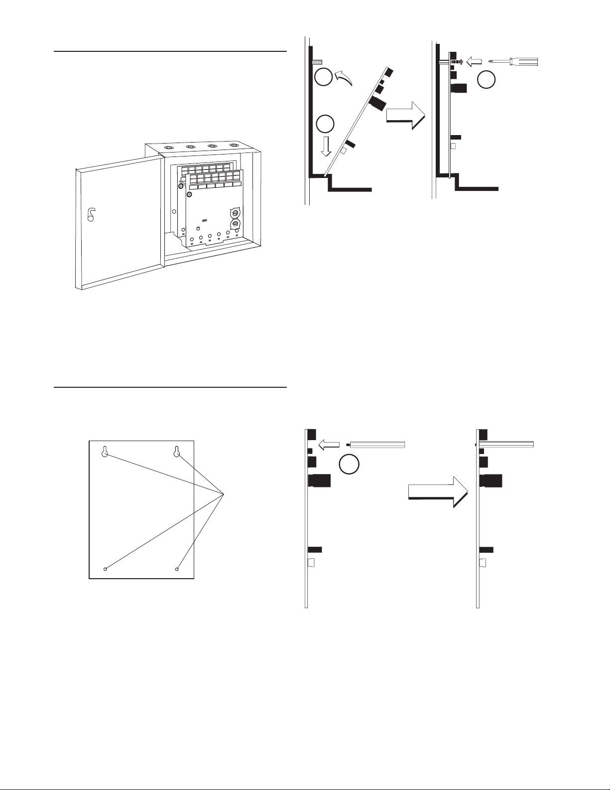
C0249-00
Figure 3: Installation of rear module only, method one
Step 1: Insert the bottom of the IDP-Relay-6 module
down into a rear slot on the chassis.
Step 2: Carefully swing the upper edge of the board
back towards the back of the chassis until it
touches the two standoffs.
Step 3: Align two 4-40 screws with the two standoffs
and tighten.
Step 4: Address and wire the modules according to the
instructions in this manual.
The steps in Figures 4a and 4b describe and illustrate module installation when the rear chassis position and the position in front of it will be filled. Front position installation
is possible only if the rear position is filled with a module.
C0235-00
Figure 2: Typical mounting hole locations
2. Module Installation
There are two methods for installing a module in the
rear position of a chassis. Method one is for installation of a rear module only, when no module will be installed in front of it. Refer to Figure 3 for instructions.
Method two is for installation of a rear module when
another module will be installed in the chassis position
in front of it. Refer to Figures 4a and 4b for method
two. All necessary screws and standoffs are supplied
with the modules.
Figure 4a: Installation of IDP-Relay-6 module in a
rear chassis position, method two
Step 1: Insert the bottom edge of the IDP-Relay-6
module down into a rear slot of the chassis.
Step 2: Carefully swing the bottom edge of the board
towards the back of the board until it touches the
short standoff attached to the chassis.
Step 3: Align the long standoff with the short standoff
and tighten.
C0244-00
K200-15-00 2 I56-2732-003
 Loading...