

Sieger Sensepoint
LEL Combustible Sensor
Operating Instructions
Issue 01 12/2005
H_MAN0590_V1
2106M0518
© 2005 Honeywell Analytics
11068
Find out more
www.honeywellanalytics.com
Customer business centre
Europe and the rest of the world
Honeywell Analytics AG
Wilstrasse 11-U11
CH-8610 Uster
Switzerland
Tel: +41 (0)44 943 4300
Fax: +41 (0)44 943 4398
sales@zelana.co.uk
Customer business center
A
mericas
Honeywell Analytics Distribution, Inc.
400 Sawgrass Corporate Pkwy
Suite 100
Sunrise, FL 33325
USA
Tel: +1 954 514 2700
Toll free: +1 800 538 0363
Fax: +1 954 514 2784
sales@zelana.com
www.honeywell.com
Please Note:
While every effort has been made to ensure
accuracy in this publication, no responsibility
can be accepted for errors or omissions.
Data may change, as well as legislation, and you
are strongly advised to obtain copies of the most
recently issued regulations, standards, and guidelines.
This publication is not intended to form the
basis of a contract.
© 2005 Honeywell Analytics
SENSEPOINT
MAN0513 .P65 Issu e 06 - 04/99
2106M 0501
SensePoi nt LEL
Combusti ble Sensor
1. INTRODU CTION
SensePo int is a sealed disp osable sens or for the detection
of fla mmable gases and is des igned for us e with an
approve d junction box.
It emp loys a cat alytic pelli stor sensor device whi ch is used
as par t of a br idge measuri ng circuit.
Sensepo int is cer tified for hazardous areas to E N50018
and is protected against wate r and dust ingress to IP66/67.
The se nsor is ava ilable in M 20, M25, M2 6 or 3/4 N PT
thread versions. All accept accessories from the specified
range.
2. ASSOCIA TED DOCUMENTATI ON
2106M05 02 SensePo int Techn ical Hand book.
Refer to the rele vant control system man ual for co nnection
informa tion.
1. INT RODUCTION & 2 . ASSOCIATED DOCUMENTATION
CONTEN TS
1. INTRODU CTION ......................................................2
2. ASSOCIA TED DOCUMENTATI ON......................... 2
3. SAFETY ....................................................................
3
3.1 Warn ings ........................................................... 3
3.2 Cautio ns............................................................. 3
4. OPERATION S ..........................................................
4
4.1 Instal lation ......................................................... 4
4.2 Calib ration ......................................................... 5
4.3 Fault finding .......................................................9
5. MAINTENANC E..................................................... 1 0
5.1 Changin g filters ................................................. 9
Appendi x A - Spe cifications ....................... 11
Appendi x B - Glo ssary ............................... 12
Appendi x C - Main features ....................... 1 3
Appendi x D - Spar e parts ........................... 14
1 2
11
12
13 14
APPENDI X C - MAIN FEATUR ESAPPENDI X A - SPECIFICATION S APPENDI X D - SPARE PARTSAPPENDI X B - GLOSSARY
Operati ng temperat ure range:
-55°C to +80°C (see certifi cation).
Operati ng humidity range:
20% to 90% RH con tinuous.
10% to 99% RH int ermittent - non condens ing.
Operati ng pressur e range:
90 to 110 k Pa.
Warm u p time:
no gre ater than 1 0 minutes.
Voltage range:
2.9 V t o 3.5 V brid ge (at 200mA ).
Power c onsumption:
700mW .
Signal output:
mV brid ge.
Calibra tion flow rate:
recomme nded between 1 and 1.5 l /min.
Poison ing:
the se nsing element s may becom e inactive after
extensi ve exposure to silic ones, haloge nated
hydroca rbons, heavy metals or sulphur co mpounds.
Expecte d operating life:
5 year s.
IP rat ing:
IP65 s tandard; IP6 6/67 with weather prot ection.
Certif ication:
Ex II 2G EExd IIC T 6 -55 to +55° C.
Ex II 2G EExd IIC T 5 -55 to +70° C.
Ex II 2G EExd IIC T 4 -55 to +80° C.
BAS98AT EX2156X.
UL app roved via IEC 79 (pen ding).
This p roduct compl ies with t he relevant CE standar ds
concern ing performa nce: EMC to BS EN50081 parts 1 & 2,
BS EN50 082 parts 1 & 2 and EN 50054.
Explosi ve gas atm osphere:
a mi xture in air of combustib le materia ls in the form of gas
vapour or mi st in which, a fter igni tion, com bustion spreads
through out the unc onsumed mixt ure.
Lower explosive li mit (LEL):
the vo lume of co mbustible ga s or vapou r in air below which
an exp losive gas a tmosphere wil l not be f ormed.
Exd:
flame proof or explosion proof withi n the confines of European
standar ds EN5 0014 and EN 50018. An e nclosure that can
wit hstan d the press ure d evelo ped d uring the inte rnal
expl osion o f an ex plosiv e mixtu re and whic h preve nts
transmi ssion of the explosion to t he explo sive at mosphere
surroun ding the enclosure.
Exe:
increas ed safety within the confines of European standards
EN50014 and EN5 0019 appli ed to e lectrical apparatus that
does no t produce a rcs or spark s in normal service, in which
additio nal measures are app lied so as to give incre ased
securit y against the possibi lity of e xcessive te mperatures.
PPS:
polymer pol yphenylene sulphi de, suitable for use in most
chem ical e nviron ments ( eg aci ds, al dehydes , keto nes,
alkalies , petroleum , aromatic hydrocarbo ns, alcohols, ethers,
esters and mos t chlorina ted hydrocarbons ). Avoid immersion
in so lvents for extended periods. F or further details contact
Zellweg er Analyti cs Ltd.
Sensor ....................................................... 2106B12 00 (M20)
Sensor ....................................................... 2106B12 01 (M25)
Sensor ....................................................... 2106B12 02 (M26)
Sensor ....................................................... 2106B12 04(3/4 NPT )
Weather protec tion ................................... 02000-A-16 40
Sensor filter ............................................... 00780-F -0018
Flow housing ............................................. 02000-A -1645
Collect ing cone ......................................... 0 2000-A-1642
Junctio n box (std) ..................................... 00780- A-0100
High te mperature ju nction box ................. 555-0 90-038
High t emperature weather pro tection ...... 00780-A-0 076
To reo rder a comp lete new se nsor, see th e label on the
product leads, or contact Z ellweger An alytics Ltd .
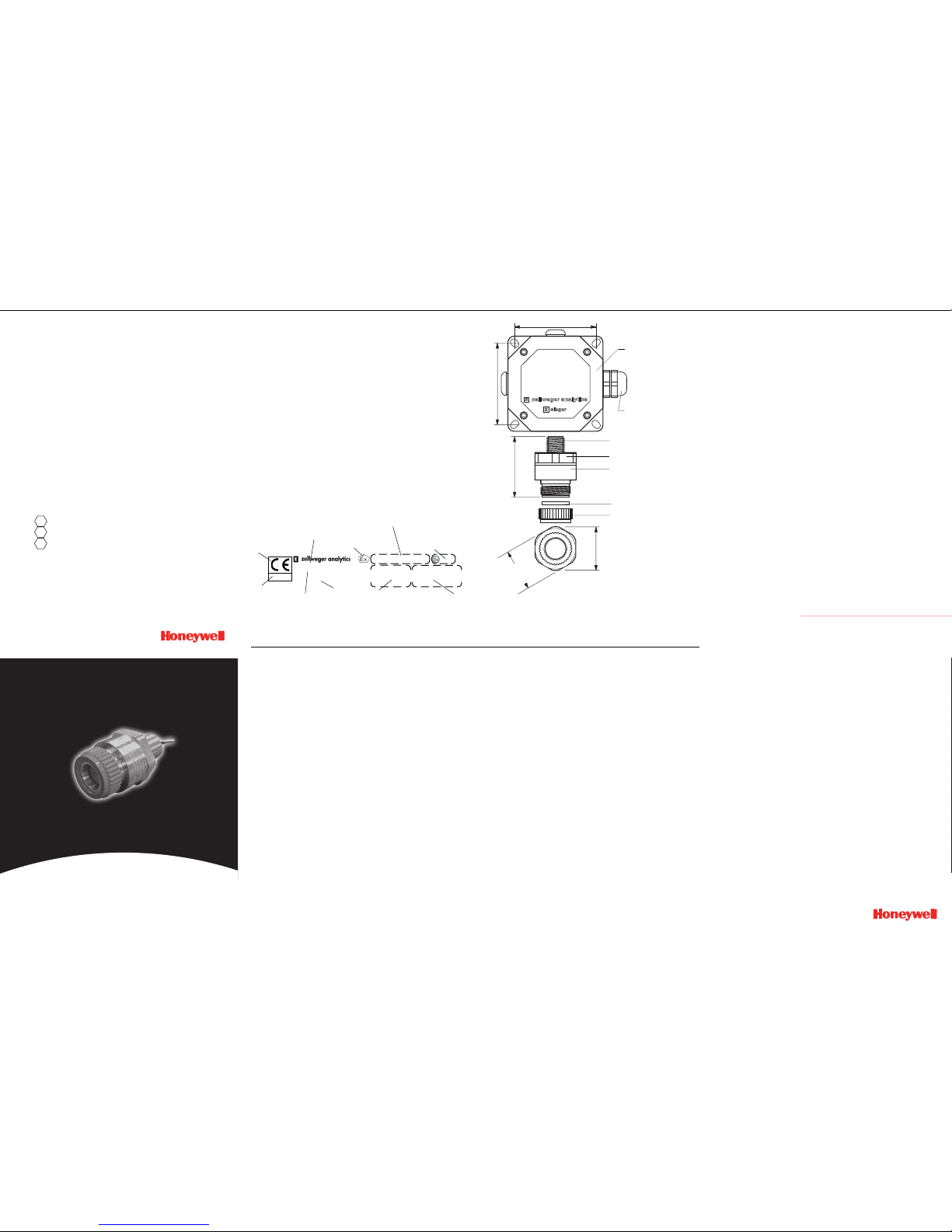
103mm
Standard Zellweger
Analytic s junction box
threads availa ble:
M20; M25; M26 ; 3/4” NPT.
SensePoi nt Combustible Gas
Sensor 0-100% LEL
Weight - 1 90g
Filter
Plastic retainer
103mm
74mm
56mm
52mm
(across flats)
Exe/Exd gland
operating instructions
Poole Dorset
SensePoint
static ri sk - read manual
EEx d IIC T6 Tamb -55 +55
o
C
EEx d IIC T5 Tamb -55 +70oC
EEx d IIC T4 Tamb -55 +80
o
C
0600
Bas98ATE X2156X II 2G
manufactur er’s
trademar k &
address
CE mark conforms to all
applicabl e
European
directives
product name
test house
trademark
certific ation code
as EN50014 1992
certific ation number
certifie d ambient
temperature
range
explosion
protecti on mark
and equipmen t
group & categ ory
ident.number
of ATEX
notified
body
caution
Certifi cation label as defined in directiv e 94/9/EC
This publication is not intended to form the basis of a contract, and the company reserved the right to
amend the design and specification of the instruments without notice.
MIDDLE EAST
Zellweger Analytics
Middle East Regional Office
PO Box 52196
Karama-Bur Dubai UAE
Tel: (971) 4 360940
Fax: (971) 4 345802
NETHERLANDS
Imbema Analytics BV
Maurisstraat 1-7
Postbus 160
2000 AD Haarlem
Netherlands
Tel: (31) 23 517 2424
Fax: (31) 23 5318040
FRANCE
Zellweger Analytics SA
33 rue de Ballon
ZI des Richardets
F-93165 Noisy le Grand
Cedex
France
Tel: (33) 01 48 15 80 80
Fax: (33) 01 48 15 80 00
GERMANY
Zellweger Analytics GmbH
Sollner Strasse 65b
D-81479 Munchen
Germany
Tel: (49) 89 791 920
Fax: (49) 89 791 9243
ITALY
Zellweger Analytics srl
Via F. Primaticcio 168
1-20147 Milano
Italy
Tel: (39) 48300436
Fax: (39) 48302314
UNITED KINGDOM
Zellweger Analytics Ltd
Parsonage Road
Takeley
Bishop’s Stortford
Herts
CM22 6PU, U.K.
Tel: (44) 1279 870182
Fax: (44) 1279 870377
SINGAPORE
Zellweger Analytics Ltd
Asia Pacific Regional Office
30, Tech Park Crescent
Singapore 638102
Tel: (65) 862 7701
Fax: (65) 862 3858
SPAIN
Zellweger Analytics SA
Avda Remolar 31
08820 EI Prat de LIobregrat
Barcelona
Spain
Tel: (34) 3 379 9611
Fax: (34) 3 379 8551
USA
Zellweger Analytics Inc
(Sieger Division)
405 Barclay Blvd
Lincolnshire
Illinois 60069,USA
Tel: (1) 847 913 0015
Fax: (1) 847 634 1371
E-mail: sieger@zelana.com
INTERNATIONAL HQ
Zellweger Analytics Ltd
Hatch Pond House
4 Stinsford Road
Nuffield Estate
Poole
Dorset
BH17 0RZ, UK
Tel: (44)1202 676161
Fax: (44)1202 678011
E-mail: postmaster@
zellweger-analytics.co.uk
Ser.No./ Year of manufacture

3
5.1 CHA NGING FILTERS
- Remo ve the grey plastic re tainer or a ccessory.
- Remo ve the old filter and replace wit h a fresh filter.
- Repl ace the gr ey plastic retainer o r accessory.
5. MAINTE NANCE
4 5
4. OPER ATIONS
Table 2: Meter Settings
* Rating of Gas to be Detected
* Calibration
Gas 8* 7* 6* 5* 4* 3* 2* 1*
8* 50 62 76 95 - - - -
7* 40 50 61 76 96 - - -
6* 33 41 50 62 78 98 - -
5* 26 33 40 50 63 79 100 -
4* 21 26 32 40 50 63 80 -
3* - 21 26 32 40 50 64 81
2* - - - 25 3 1 39 50 64
1* - - - - 25 31 39 50
Note: The se settings must only be used wi th a calibr ation
gas co ncentration of 50% LEL.
Cross Calibration example:
The target gas to be de tected is B utane. The calibration
gas av ailable is Methane (5 0% LEL).
Look up the st ar rating f or each gas (Table 1) :
Butane 4*, Methane 6*
Chec k the meter settings f or 50% LEL calibration gas
(Table 2).
The control car d meter sho uld therefor e be set t o 78%
to giv e an accura te reading f or Butane, using 50% L EL
Methane as a cal ibration ga s.
4.3 F AULT FINDING
Sensor reads non ze ro all the ti me:
- gas co uld be pres ent, ensure there is no combusti ble
gas in the atmosph ere.
Sensor reads non zer o when no ga s is present:
- adjust the zero of the control system.
Sensor reads low w hen gas is a pplied:
- adjust the span of the control system.
Sensor reads high when gas is applied:
- adjust the span of the control system.
Sensor reads zero when gas is applied:
- check the wiring.
- check t hat the dus t protection cap has be en removed.
- check that the si nter is not obstructed .
- replace the senso r if poiso ning is su spected.
Table 3: Meter Mu ltiplication Factors
Unit calibrated Unit used to detect
To Detect 8* 7* 6* 5* 4* 3* 2* 1*
8* 1.00 1.24 1.52 1 .89 2.37 2.98 3.78 4.83
7* 0.81 1.00 1.23 1 .53 1.92 2.40 3.05 3.90
6* 0.66 0.81 1.00 1 .24 1.56 1.96 2.49 3.17
5* 0.53 0.66 0.80 1 .00 1.25 1.58 2.00 2.55
4* 0.42 0.52 0.64 0 .80 1.00 1.26 1.60 2.03
3* 0.34 0.42 0.51 0 .64 0.80 1.00 1.27 1.62
2* 0.26 0.33 0.40 0 .50 0.63 0.79 1.00 1.28
1* 0.21 0.26 0.32 0 .39 0.49 0.62 0.78 1.00
4. OPER ATIONS
4. OPER ATIONS
Grey plasti c retainer
Filter
Main body of se nsor
4.1 IN STALLATION
The Se nsePoint mu st be fitt ed into a suitably a pproved Exe
or Exd junctio n b ox fitted with a suitably app roved cable
gland. This should b e correctly i nstalled befo re use. Cabli ng
should be multi core, thre e wire m inimum, of conductor size
2.5 mm
2
max.
The sensor sh ould be fitted into a threaded hole wi thin the
junctio n box and loc ked in place with a lock n ut. Ensure th at
junctio n box threa d is compat ible with s ensor thread .
The se nsor should be install ed in a l ocation free from dire ct
heat sources . It shoul d be fitte d suc h th at it eith er po ints
downwar ds or horizonta lly. It is not rec ommended that th e
sensor points up wards. See the techni cal handbo ok for
install ation in forced a ir conditi ons.
Wiring connections are:-
4. OPER ATIONS 4. OPER ATIONS
3.1 WARNINGS
This apparatus is not suit able for use in
oxygen enriched a tmospheres ( >21%V/V).
Oxygen deficient atmosphe res (<10% V/V)
may sup press sensor output.
Refer to loc al or nat ional reg ulati ons
relativ e to insta llation at the site.
Operator should be fully awar e of the action
to be taken if the gas concentration exceeds
an ala rm level.
Sense Poin t sh ould be pro tect ed fr om
mec hanic al im pact. Inst allat ion sh ould
conside r not only th e best placing for gas
leakage related to potential l eak points,
gas charac teristics and venti lation, but also
where t he potential of mechani cal damage
is min imized or a voided.
3.2 CAUTIONS
Atmo sph eres a bove 1 00% L EL ma y
suppres s the sens or reading.
Do n ot m odi fy o r al ter t he s ens or
co nstr ucti on as es sent ial sa fety
require ments may be invalida ted.
Install using certified Exe or Ex d junc tion
box, c onnectors a nd glanding .
Dispose of in accordance with local disposal
reg ulat ions . Mat eria ls u sed -Fo rtro n®
(PPS- Polyphenyle ne Sulphid e).
3. SAF ETY
4.2 CA LIBRATION
Pri or to cal ibrati on, a llow the sen sor to warm up f or
approxi mately 10 mi nutes. Re-cal ibration shou ld only be
attempt ed by qua lified ser vice person nel.
First zero the contro l system with no gas present on the
sensor. If com bustible gas is suspected to be in the vicinity of
SensePoint, flow clean air over the sensor using a flow housing
(see below) .
Fit a flow hou sing and connect a cylinder o f either air, for a
zero, or a know n concent ration of gas in air, at appr oximately
the alarm point (e. g. 50% LEL), to the flo w housing. Pass th e
gas thr ough the flo w housing at a flow rate of approxima tely
1 l to 1 .5 l per minut e. Allow the sensor to stabilis e. When
gassing with air, ad just the cont rol card to i ndicate zero. For
span, the contr ol c ard should be adjusted to indicat e th e
concent ration o f the target gas be ing appl ied. Rem ove the
flow h ousing and the gas sup ply.
Sensors should be calibrated at concentra tions representative
of those to be measured . It is alw ays recommended that
SensePo int is cali brated with the target gas it is to detect. I f
this i s not poss ible, then cross cali bration can be used.
For ca libration in fast f low condi tions see the te chnical
handbo ok.
4.3 CR OSS CALIBRATIO N PROCEDURE
When the Sense Point sens or is t o be c alibrated with a gas
which i s different t o the gas/va pour to be de tected, the
followi ng cross calibration procedure should be followed.
Table 1 l ists gases acco rding to the rea ction they prod uce at
the detecto r. A n ei ght star (8*) gas produces the highes t
output while a one star (1*) g as produces the lowest o utput.
(These are not a pplicable a t ppm leve ls.)
4. OPER ATIONS
To calibr ate the SensePo int sensor, obta in the star ratin g for
both the te st gas and t he gas to be detected from table 1.
These value s m ay then be used in table 2 to obtain the
require d meter setting whe n a 50% LEL test gas is appl ied to
the de tector.
If a sensor is to be used to detect a gas other than that for
which it wa s calibrated, the re quired correction fac tor may be
obtained from tab le 3. The meter reading should be mul tiplied
by this n umber in order to obtain the true gas concentration.
IMPORTA NT
Si nce combustibl e sensors requir e oxygen for corr ect
operati on, a mixture of gas in air sh ould be used for
calibra tion pu rposes.
As suming an average sens or performance, the sensitivi ty
informa tion in tables 1 to 3 is norm ally accurate to ± 20%.
Table 1: Star R ating of Ga sses
7 8 9 10
6
Gas Star Rating
Acetone 4*
Ammonia 7*
Benzene 3*
Butane 4*
Diethyl ether 4*
Ethane 6*
Ethanol 5*
Ethyl acetate 3*
Ethylene 5*
Gas Star Rating
Hexane 3*
Hydrogen 6*
Methane 6*
Octane 3*
Propan-2-ol 4*
Propane 5*
Styrene 2*
Tetra hydrafuran 4*
Xylene 2*
The uni t requires 200mA curre nt with a n ominal 3V s upply.
Install ation and service are to be pe rformed b y a qu alified
in stal lati on eng ine er w ith th e po wer to the se nsor
discon nected.
SENSITIVE
(S)
NON
SENSITIVE
(NS)
COMMON
(01)
SPARE
BROWN BLUE WHITE
SENSOR

Thank you for reading this data sheet.
For pricing or for further information, please contact us at our UK Office, using the details
below.
UK Office
Keison Products,
P.O. Box 2124, Chelmsford, Essex, CM1 3UP, England.
Tel: +44 (0)330 088 0560
Fax: +44 (0)1245 808399
Email: sales@keison.co.uk
Please note - Product designs and specifications are subject to change without notice. The user is responsible for determining the
suitability of this product.
 Loading...