

Page 1
Technical Handbook
Sieger Apex
Page 2
MAN0604 Issue 04 Feb 04 Apex
2110M8030
SAFETY
Ensure that you read and understand this handbook BEFORE installing/operating the
equipment. Pay particular attention to the Safety Warnings.
WARNINGS
1. This gas detection equipment is certified for and intended for use in potentially hazardous areas.
Install and use the equipment in accordance with current local and national regulations.
2. Refer to the control drawings included in this document when installing the certified components.
3. Operators should be fully aware of the action to be taken if the gas concentration exceeds alarm level.
4. Do not modify or alter the construction of any of the units as essential safety and certification requirements
may be invalidated.
5. The equipment is not suitable for use in oxygen enriched atmospheres (>21%V/V). Oxygen deficient
atmospheres (<10% V/V) may suppress some sensor outputs.
6. The equipment is intended for use at atmospheric pressure only and should not be used in pressures
exceeding 1.1 bar.
Transmitter Unit only
1. INPUT VOLTAGE MUST NOT EXCEED THE STATED MAXIMUM (32V DC) AS ESSENTIAL
SAFETY REQUIREMENTS MAY BE INVALIDATED AND THE UNIT MAY BE PERMANENTLY
DAMAGED.
2. Alarms should not be reset until it is confirmed that gas is not present.
3. Hazardous voltages may exist at alarm contacts. Ensure power is disconnected at source prior to
servicing contacts.
4. Gas events occurring while accessing the Transmitter Unit menus will not be reported locally.
5. Overrange flammable gas readings may indicate an explosive concentration of gas.
Certified Sensor only
1. When installed to measure flammable gas it is essential that either the Transmitter unit or
control network is configured to latch the overrange condition. If the Transmitter unit local
relays are used this should be achieved by enabling the overrange latching function of the
Transmitter unit. Depletion of oxygen as a consequence of displacement by flammable gas
can result in the gas reading returning to zero.
2. Change gas cartridges using the procedure described in this handbook. Failure to correctly follow the
procedure could result in the wrong cartridge being installed, and possibly non-detection of events.
Alternatively, extraneous alarms could be triggered by chemicals detected but not of concern at a
particular location.
3. Sensor cartridges may contain corrosive solutions. Dispose of in accordance with local and national
regulations.
4. During usage, as some gases may be hazardous, outlets from accessories, etc., e.g. Flow Housing,
should exhaust to a safe area.
2
Page 3

MAN0604 Issue 04 Feb 04 Apex
2110M8030
SAFETY
CAUTIONS
1. Only the combustible gas detection portion of this instrument has been assessed for performance
by CSA.
2. Refer to local or national regulations relative to installation and use at the site.
3. Installation should consider not only optimum siting for gas detection related to potential leak points, gas
characteristics and ventilation but also placement where the potential for mechanical damage is minimised
or avoided.
4. Observe precautions for handling electrostatic discharge sensitive devices when accessing the interior
of the Transmitter Unit.
5. Calibration procedures should only be performed by qualified personnel.
6. Ensure that when forcing signals on the Transmitter Unit’s output that the effects on the network and
controller are understood.
7. Ensure that the Apex Transmitter Unit or Junction Box flamepath is not damaged during dismantling
procedures. The flamepath is formed by the mating surfaces of the unit’s top and base.
8. During installation/maintenance only use the supplied parts. Replacement with alternatives will invalidate
certification.
9. Exposure to fluorinated hydrocarbons or silicones will poison the sensor beads on catalytic sensor
cartridges. If a sensor is known to have been poisoned then it must be re-calibrated. If not sure then
flow gas over the sensor and if the reading is incorrect re-calibrate within the cartridge’s tolerance value.
10. Only cartridges with the following part numbers can be fitted to the Certified Sensor:
2110B30x0, 31x0, 32x0, 33x0, 34x0 series
2110B3700 - 2110B3999 range
Note: Certified to CSA C22.2 No. 152 only when fitted with specific cartridges.
See specifications for details.
Performance assessed to EN50054/57 when fitted with cartridges
Part No: 2110B3701& 2110B3704. See specifications for detail.
11. When compliance with the ATEX EN50054 performance standard is required the warning and inhibit
current shall not be configured to a value between than 3.1mA and 4.9mA
12. Do not use the unit where the temperature is lower than -40
o
+65
C (149oF).
o
C (-40oF) or higher than
13. Exposures to gas above the recommended range may result in ambiguous readings and may require
subsequent re-calibration of the sensor.
14. Review cartridge data sheets for operating temperatures and humidities, which are determined on a
cartridge by cartridge basis.
15. Dispose of in accordance with local disposal regulations. Materials used:
Transmitter Unit
Main Body: Stainless Steel
User Interface: Zinc Alloy.
Certified Sensor
Main Body: Stainless Steel
Certified Junction Box
Main body: Stainless steel.
3
Page 4

MAN0604 Issue 04 Feb 04 Apex
2110M8030
HELP US TO HELP YOU
Every effort has been made to ensure the accuracy in the contents of our documents, however, Zellweger
Analytics Limited can assume no responsibility for any errors or omissions in our documents or their
consequences. Zellweger Analytics Limited would greatly appreciate being informed of any errors or
omissions that may be found in our documents. To this end we include the following form for you to
photocopy, complete and return to us so that we may take the appropriate action.
To: Marketing Communications
Zellweger Analytics Limited
Hatch Pond House
4 Stinsford Road
Nuffield Estate
POOLE. Dorset
BH17 0RZ
United Kingdom
Tel.: +44 (0) 1202 676161
Fax.: +44 (0) 1202 678011
E-mail : sales@zelana.co.uk
I suggest the following corrections/changes be made to: ..................
From:
Address:
Tel.:
Fax.:
E-mail:
Marked up copies attached (as appropriate): Yes / No
Please inform me of the outcome of this change: Yes / No
For Marketing Communications, Zellweger Analytics Limited:
Actioned By:
Date:
Response:
Date:
4
Page 5

MAN0604 Issue 04 Feb 04 Apex
2110M8030
CONTENTS
SAFETY 2
HELP US TO HELP YOU 4
1. INTRODUCTION 8
2. OVERVIEW 10
2.1 Transmitter Unit 10
2.2 Certified Sensor 12
2.3 Accessories 14
2.3.1 Certified Junction Box 14
2.3.2 Collecting Cone 16
2.3.3 Flow Housing 17
2.3.4 Weather Housing 18
2.3.5 Sunshade 18
2.3.6 Oxygen Transducer Adaptor 19
2.3.7 Filters 19
3. INSTALLATION 20
General Installation Guidelines 21
3.1 Transmitter Unit and Certified Sensor 22
3.1.1 Installing the Transmitter Unit 22
3.1.2 Fitting the Certified Sensor 25
3.1.3 Installing the Gas Sensing Cartridge 27
3.1.4 Transmitter Unit Configuration 29
3.2 Certified Junction Box and Certified Sensor 31
3.2.1 Installing the Certified Junction Box 32
3.2.2 Fitting the Certified Sensor 34
3.2.3 Installing the Gas Sensing Cartridge 36
3.2.4 Certified Junction Box Configuration 37
3.3 LonWorks Communications Board 38
3.3.1 Removing the Transmitter Unit top 39
3.3.2 Removing the Main PCB assembly from the top 40
3.3.3 Fitting the LonWorks Communication Board to
the Main PCB 40
3.3.4 Refitting the Main PCB Assembly into the Top 41
3.3.5 Connecting the LonWorks Network Wiring 42
3.3.6 Refitting the Transmitter Unit Top 43
3.4 Accessories 46
3.4.1 Flow Housing, Weather Protection, Collecting Cone 46
3.4.2 Sunshade 47
5
Page 6

MAN0604 Issue 04 Feb 04 Apex
2110M8030
CONTENTS
4. OPERATION 49
4.1 Display and Control Buttons 49
4.1.1 LCD screen 50
4.1.2 Control buttons 50
4.2 Start-up 51
4.3 Passwords 52
4.3.1 Setting/changing passwords 53
4.3.2 Password reset 55
4.4 Menus 56
4.4.1 Calibration Menu 57
4.4.2 Configuration Menu 63
4.4.3 Display Menu 71
4.4.4 History Log Menu 74
4.4.5 Change Passwords Menu 75
4.4.6 Reset Passwords 76
4.5 User Tasks 77
4.6 Fault Diagnosis 78
4.6.1 Displayed Error Messages 78
4.6.2 General Faults 79
4.6.3 4-20mA output signal ranges and fault conditions 80
4.6.4 Clearing latched alarms 81
4.7 System Calibration 82
4.8 Binding Communication Boards to Networks 87
5. MAINTENANCE 89
5.1 Routine maintenance schedule 89
5.2 Maintenance Procedures /Parts Replacement 90
5.2.1 Changing the Certified Sensor Filter 90
5.2.2 Changing the Certified Sensor Cartridge 91
5.2.3 Changing the Certified Sensor 95
5.2.4 Changing the Transmitter Unit Front Panel Assembly 98
APPENDIX A - SPECIFICATIONS 100
A.1 Transmitter Unit and Sensor 100
A.1.1 Gases and Ranges 100
A.1.2 Input/Output 100
A.1.3 Monitoring functions 102
A.1.4 Performance 102
6
Page 7

MAN0604 Issue 04 Feb 04 Apex
2110M8030
CONTENTS
A.1.5 Environmental 102
A.1.6 Storage (excluding cartridge) 102
A.1.7 EMC 103
A.1.8 Enclosure 103
A.1.9 Configuration 103
A.1.10 Certification and Approvals 103
A.1.11 Calibration intervals 105
A.2 Cartridges 105
A.2.1 Cartridge tables 105
A.3 Accessories 111
A.3.1 Certified Junction Box 111
A.3.2 Sunshade 112
A.3.3 Flow Housing 113
A.3.4 Weather Protection 113
A.3.5 Collecting Cone 113
A.3.6 Oxygen Transducer Adaptor 113
A.4 LonWorks Communications Board 113
A.4.1 LonWorks Network Variables 114
A.4.2 Node Object 114
A.4.3 Sensor Object 116
A.4.4 Virtual Function Block 117
A.4.5 Implementation of nviRequest 118
A.4.6 Interpretation of nvoStatus 119
APPENDIX B - CERTIFICATION 120
B.1 Transmitter Unit 120
B.2 Certified Sensor 121
B.3 Certified Junction Box 123
B.4 Accessories 124
B.5 Control Drawings 125
APPENDIX C - ACCESSORIES & SPARE PARTS 127
C.1 Accessories 127
C.2 Digital Communications Board 127
C.3 Spares 127
APPENDIX D - GLOSSARY 128
7
Page 8

MAN0604 Issue 04 Feb 04 Apex
2110M8030
1. INTRODUCTION
Apex is a gas detection system that consists of a Transmitter Unit, a certified
gas sensor and a set of accessories. The Transmitter Unit, Certified Sensor
and Certified Junction Box accessory are all certified for use in potentially
hazardous areas and are protected against water and dust ingress to
IP67.
Typical working environments are oil and gas distribution, petroleum
extraction and chemical manufacture.
System installation is straightforward. Components should be installed in
accordance with the procedures described in this handbook and to local
or national installation codes of practice.
The Transmitter Unit acts as the local system controller and features a
large LCD screen and four control buttons that are used for operator
interaction. Control of the system is implemented via a system of softwaredriven hierarchical menus that include such operations as cartridge change,
system configuration, etc. Remote control of the system can be made via
an optional digital interface.
The Transmitter Unit can have the Certified Sensor fitted to it locally or
mounted remotely using a Certified Junction Box and additional cabling
up to 100 metres long.
The Transmitter Unit provides a 4-20mA output, as well as an optional
digital output. Relays for operating locally-wired devices, such as lights,
horns, etc. are included. The range of accessories enhances operation of
the system and includes a collecting cone, weather protection, etc.
The Certified Sensor is compatible with a range of more than 40 sensor
cartridges that use catalytic bead, thick film and electrochemical cells.
The interchangeable sensor cartridge determines which gas is monitored.
All gas cartridges are fully calibrated when supplied.
The Certified Sensor uses intrinsically safe circuits to drive the cartridges.
Cartridges may therefore be exchanged without powering down even in
the presence of an explosive gas atmosphere.
Field calibration of the sensor, if required, is also possible. The cartridges
available are listed in Appendix A.
The output from the sensor provides a gas concentration reading that is
displayed on the LCD screen on the front of the Transmitter Unit and is
also transmitted on the 4-20mA output and the optional digital interface.
8
Page 9

MAN0604 Issue 04 Feb 04 Apex
2110M8030
1. INTRODUCTION
This handbook consists of the following parts:
• Chapter 1 Introduction
• Chapter 2 Overview
• Chapter 3 Installation
• Chapter 4 Operation
• Chapter 5 Maintenance
• Appendix A Specifications
• Appendix B Certification
• Appendix C Accessories & Spare Parts
• Appendix D Glossary
Information notices
The types of information notices used throughout this handbook are as
follows:
WARNING
!
Caution: Indicates hazardous or unsafe practice which could result in
Note: Provides useful/helpful/additional information.
Trademarks
The following trademarks are used in this handbook:
Teflon® and Freon® are registered trademarks of E.I. DuPont de Nemours
and Co.
LonWorks®, Echelon®, Neuron®, and LonTalk® are registered trademarks
of Echelon Corporation.
If more information outside the scope of this technical handbook is required
please contact Zellweger Analytics.
Indicates hazardous or unsafe practice which could result
in severe injury or death to .personnel
minor injury to personnel, or product or property damage.
9
Page 10
MAN0604 Issue 04 Feb 04 Apex
2110M8030
2. OVERVIEW
This chapter provides an overview of the following system components,
and provides their dimensions:
• Transmitter Unit
• Certified Sensor
• Accessories
For installation information see Chapter 3.
Also see drawing 2110C8049 Outline Dimensions of Certified
Transmitter, Sensor & Accessories (available on request from Zellweger
Analytics).
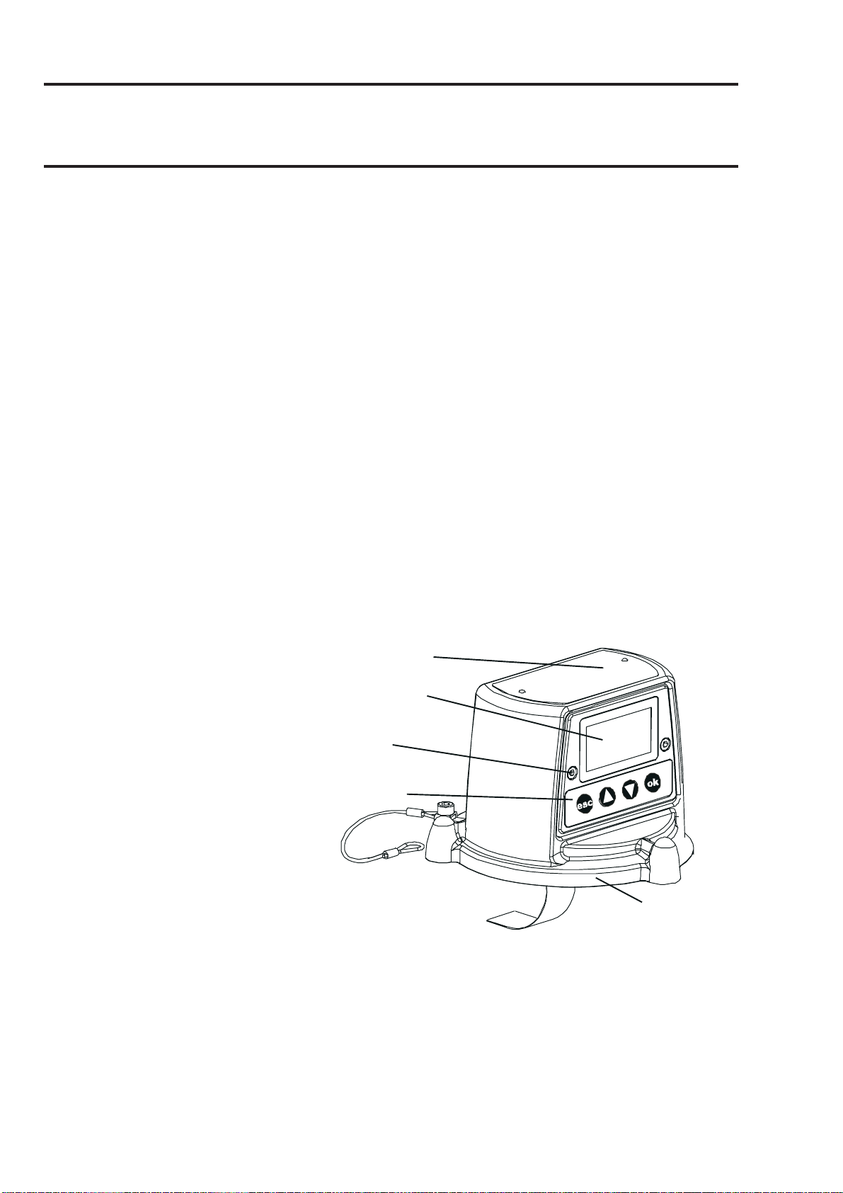
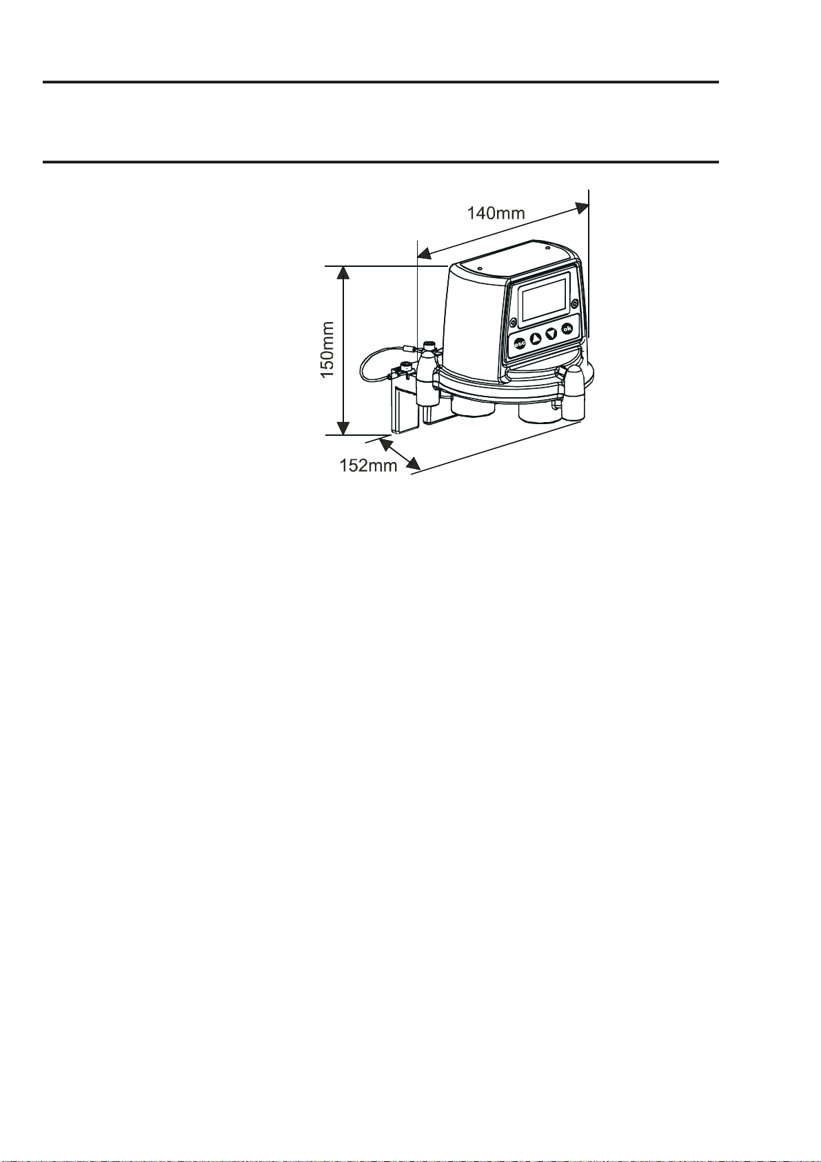
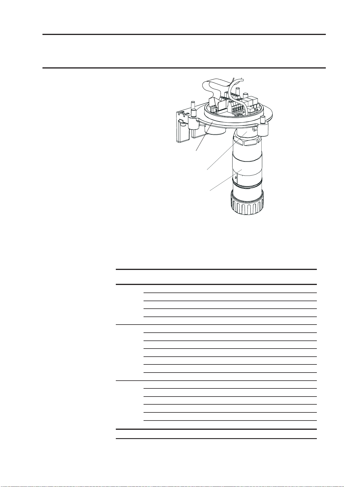
2.1 TRANSMITTER UNIT
The Transmitter Unit provides a mounting point for a Certified Sensor
and contains all the electronics associated with the gas detection system.
It features an LCD display screen that displays the controlling software
menu system, and also a set of buttons that let an operator/user interact
with the system by accessing the menus and responding to displayed
messages.
The Transmitter Unit is shown with a Certified Sensor fitted.
Certification label
LCD screen
LCD screen assembly
securing screw
(2 off)
Buttons
Top retaining
cable
Ribbon cable
10
Unit top
Page 11
MAN0604 Issue 04 Feb 04 Apex
2110M8030
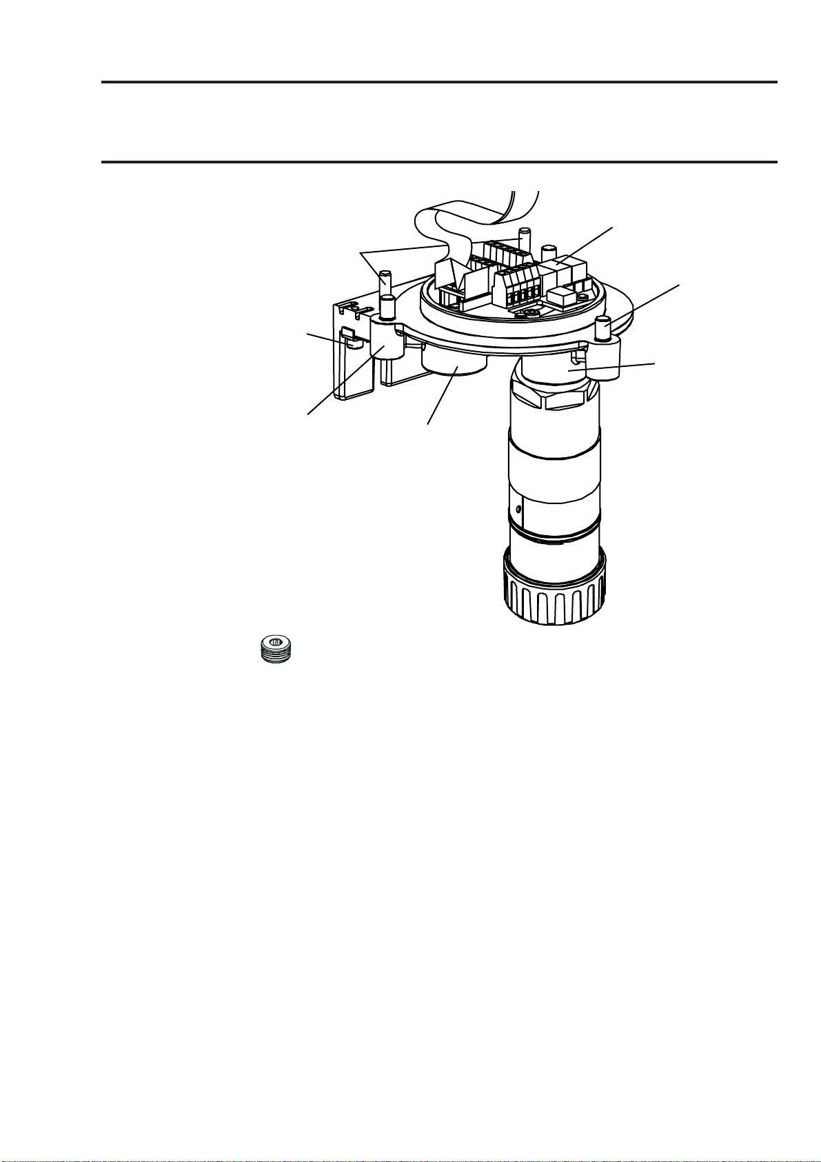
2. OVERVIEW
Interconnect PCB
Locating pins
Captive bolt
External
earth
Sensor mounting
Unit base
Cable/conduit
entry (2 off)
(3 off)
Certified
Cable/conduit entry sealing plug (1 off)
11
Page 12
MAN0604 Issue 04 Feb 04 Apex
2110M8030
2. OVERVIEW
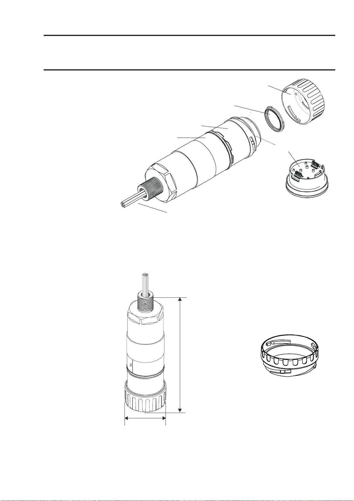
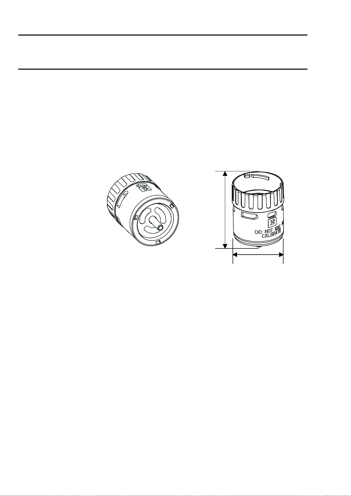
2.2 CERTIFIED SENSOR
The Certified Sensor consists of the sensor body and one of four types
of replaceable gas cartridge and the electronics to output gas sensing
data to the Apex Transmitter Unit. The Certified Sensor can be fitted with
any one of a number of accessories, the majority of which fit in place of
the sensor cap (see 2.3).
The four types of cartridge are:
• electrochemical cell
• catalytic (SG16 type)
• oxygen
• thick film
Caution: Only cartridges with the following part numbers can be
fitted to the Certified Sensor:
2110B30x0, 31x0, 32x0, 33x0, 34x0 series
2110B3700 - 2110B3999 range
Certified Sensor approved to CSA C22.2 No. 152 only when fitted with
specific cartridges installed. See specifications for details.
The sensor should be mounted in the vertical orientation with the
cartridge facing downwards.
12
Page 13
MAN0604 Issue 04 Feb 04 Apex
2110M8030
2. OVERVIEW
Cap or accessory
Seal or
filteroptional
Sensor body
Certification label
Cartridge
Sensor cable
All the gas cartridges are the same size except for the Oxygen cartridge,
which is larger than the rest. To allow for its extra length an Oxygen
Transducer Adaptor, supplied with the cartridge, mounts on the sensor
bayonet fixing. The Oxygen cartridge is then inserted and the cap or
accessory fitted.
165mm
(177mm with
Z
E
L
L
W
E
G
R
E
Oxygen
transducer)
Oxygen transducer
adaptor
53mm
13
Page 14

MAN0604 Issue 04 Feb 04 Apex
2110M8030
2. OVERVIEW
2.3 ACCESSORIES
The Apex accessories provide optional equipment that can, for example,
protect the Certified Sensor in harsh external environments and assist
gas monitoring. All of the sensor accessories are easily fitted.
The following accessories are available:
• Certified Junction Box (Part Numbers: ATEX EEXd
2110B2100, UL/CSA [Explosion proof] 2110B2103) - two
types for remote mounting a Certified Sensor.
• Collecting Cone (Part No: 2110B2151) - for use when
monitoring lighter-than-air gases.
• Flow Housing (Part No: 21110B2140) - to aid sensor
calibration and gas sample monitoring.
• Weather Housing (Part No: 2110B2150) - to protect the
sensor from harsh weather.
• Sunshade (Part No: 2110B2152) - to protect the sensor
from direct sunlight.
• Filters - three different filters to provide protection for the
gas sensing cartridge.
• O2 Transducer Adaptor - supplied with Oxygen cartridges to
allow for their longer length over standard cartridges.
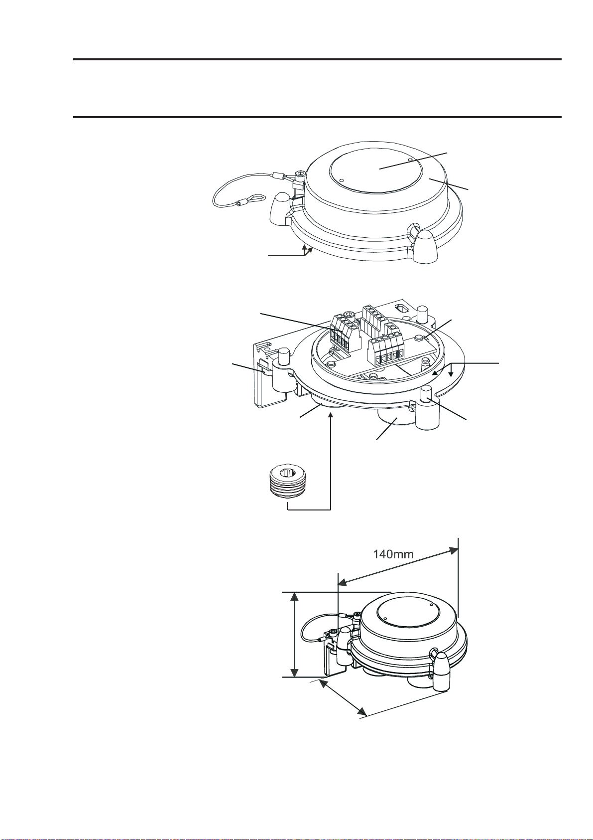
2.3.1 Certified Junction Box
Part Numbers:
ATEX EEXd 2110B2100
UL/CSA (Explosion proof) 2110B2103
The Certified Junction Box accessory is used to mount a Certified Sensor
remotely from the Transmitter Unit, and provides a connection point for
the sensor and field wiring.
14
Page 15
MAN0604 Issue 04 Feb 04 Apex
2110M8030
2. OVERVIEW
Lid retaining
cable
Flamepath
Terminal block
(3 off)
External
earth
Cable / conduit
entry (2 off)
Cable entry
sealing
plug (1 off)
Certification label
Certified Junction
Box Top
Interconnect PCB
Flamepath
Captive bolt
(3 off)
Sensor
mounting point
95mm
152mm
15
Page 16
MAN0604 Issue 04 Feb 04 Apex
2110M8030
2. OVERVIEW
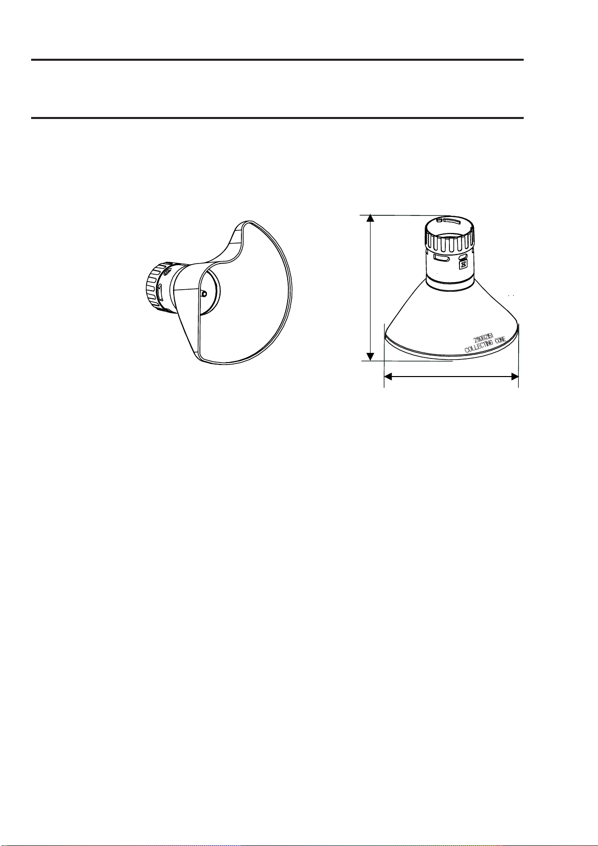
2.3.2 Collecting Cone
Caution: This accessory should not be used for calibration
purposes.
Part Number: 2110B2151
127mm
160mm
The Collecting Cone is only for use when monitoring lighter-than-air gases.
Its shape is designed to:
• increase the collection area for lighter than air gases
• allow the gases to escape so that the time to clear an alarm is
not excessively prolonged.
• fit against a wall or other flat surface
Conforms to CSA C22.2 No. 152 when fitted to the Certified Sensor
specific cartridges installed. See specifications for details.
The performance of this accessory has not been evaluated to EN50054/57
The Collecting Cone is attached to the sensor by means of a bayonet
fitting.
Inside the cone is a 1/4in. O/D nozzle that can accept a tube and which
provides a means to directly inject gas to the front of the sensor for gas
response checking. The recommended flow rate for response checks is
1 litre per minute.
with
Accuracy of reading is not guaranteed.
Note: Do not carry out response checks at wind speeds greater than
10m/s (22mph).
16
Page 17

MAN0604 Issue 04 Feb 04 Apex
2110M8030
2. OVERVIEW
2.3.3 Flow Housing
Part Number: 2110B2140
43mm
53mm
The Flow Housing accessory provides a means of applying gas to the
sensor for calibration and test (for details see section 4.7). It can also be
used in sampling systems where a sample of gas is drawn through a
tube to the sensor. Conforms to CSA C22.2 No. 152 when fitted to the
Certified Sensor with specific cartridges installed. See specifications
for details.
It provides:
• Two ports 8mm I/D to take 6mm tubing.
• A seal to stop gas dilution.
The housing works irrespective of which pipe the gas is applied to and
flows gas across the face of the sensor rather than onto its face.
The difference in reading between a calibration made with the Flow
Housing accessory and one made under diffusion conditions (in a tank of
still gas) is less than 30%. The Flow Housing is suitable for flow rates in
the range of 0.7 - 1 litre per minute flow across the cell.
A hydrophobic filter is supplied with the housing which must be used
when calibrating sensors fitted with flammable gas cartridges.
When calibrating sensors fitted with other types of cartridge then the filter
mounted in the sensor cap for normal gas sensing operation (if fitted)
must be removed and used in the Flow Housing.
The Flow Housing accessory is attached to the sensor by means of a
17
Page 18
MAN0604 Issue 04 Feb 04 Apex
2110M8030
2. OVERVIEW
bayonet fitting.
2.3.4 Weather Housing
Caution: This accessory should not be used for calibration
purposes.
This accessory is not recommended for use in still air
conditions.
Part Number: 2110B2150
75mm
53mm
The Weather Housing accessory protects the sensor from hosing down/
cleaning operations and from extreme weather conditions, (e.g. torrential
rain, storms, gales etc.). Conforms to CSA C22.2 No. 152 when fitted to
the Certified Sensor with specific cartridges installed. See specifications
for details.
The weather housing should not be fitted if the operating environment of
the sensor does not require the additional protection afforded. In still air
conditions the gas is transported to the face of the sinter is by diffusion
only. Under such conditions the weather protection will slow the rate at
which gas can reach the sensing element and consequently the speed of
response of the sensor to gas will be reduced.
As well as providing weather protection the housing also provides a means
to directly inject gas to the front of the sensor via a 1/4in. O/D nozzle for
gas response checking. The recommended flow rate for response checks
is 1 litre per minute. Accuracy of reading is not guaranteed. Do not carry
out response checks at wind speeds greater than 10m/s (22mph).
The accessory is attached to the sensor by means of a bayonet fitting.
Note: The sensor will exhibit an increased reading(or indication) to gas
with higher wind speeds. Fitting the weather housing with the supplied
hydrophobic filter will eliminate this effect but increase the response time.
18
Page 19
MAN0604 Issue 04 Feb 04 Apex
aaaaaaaaaaaaaaaa
aaaaaaaaaaaaaaaa
aaaaaaaaaaaaaaaa
aaaaaaaaaaaaaaaa
aaaaaaaaaaaaaaaa
aaaaaaaaaaaaaaaa
aaaaaaaaaaaaaaaa
aaaaaaaaaaaaaaaa
aaaaaaaaaaaaaaaa
aaaaaaaaaaaaaaaa
aaaaaaaaaaaaaaaa
aaaaaaaaaaaaaaaa
aaaaaaaaaaaaaaaa
aaaaaaaaaaaaaaaa
aaaaaaaaaaaaaaaa
aaaaaaaaaaaaaaaa
aaaaaaaaaaaaaaaa
aaaaaaaaaaaaaaaa
aaaaaaaaaaaaaaaa
aaaaaaaaaaaaaaaa
aaaaaaaaaaaaaaaa
aaaaaaaaaaaaaaaa
aaaaaaaaaaaaaaaaaaaaaaaaaaaaaaa
aaaaaaaaaaaaaaaaaaaaaaaaaaaaaaa
aaaaaaaaaaaaaaaaaaaaaaaaaaaaaaa
aaaaaaaaaaaaaaaaaaaaaaaaaaaaaaa
aaaaaaaaaaaaaaaaaaaaaaaaaaaaaaa
aaaaaaaaaaaaaaaaaaaaaaaaaaaaaaa
aaaaaaaaaaaaaaaaaaaaaaaaaaaaaaa
aaaaaaaaaaaaaaaaaaaaaaaaaaaaaaa
aaaaaaaaaaaaaaaaaaaaaaaaaaaaaaa
aaaaaaaaaaaaaaaaaaaaaaaaaaaaaaa
aaaaaaaaaaaaaaaaaaaaaaaaaaaaaaa
aaaaaaaaaaaaaaaaaaaaaaaaaaaaaaa
aaaaaaaaaaaaaaaaaaaaaaaaaaaaaaa
aaaaaaaaaaaaaaaaaaaaaaaaaaaaaaa
aaaaaaaaaaaaaaaaaaaaaaaaaaaaaaa
aaaaaaaaaaaaaaaaaaaaaaaaaaaaaaa
aaaaaaaaaaaaaaaaaaaaaaaaaaaaaaa
aaaaaaaaaaaaaaaaaaaaaaaaaaaaaaa
aaaaaaaaaaaaaaaaaaaaaaaaaaaaaaa
aaaaaaaaaaaaaaaaaaaaaaaaaaaaaaa
aaaaaaaaaaaaaaaaaaaaaaaaaaaaaaa
aaaaaaaaaaaaaaaaaaaaaaaaaaaaaaa
aaaaaaaaaaaaaaaaaaaaaaaaaaaaaaa
aaaaaaaaaaaaaaaaaaaaaaaaaaaaaaa
aaaaaaaaaaaaaaaaaaaaaaaaaaaaaaa
aaaaaaaaaaaaaaaaaaaaaaaaaaaaaaa
aaaaaaaaaaaaaaaaaaaaaaaaaaaaaaa
aaaaaaaaaaaaaaaaaaaaaaaaaaaaaaa
aaaaaaaaaaaaaaaaaaaaaaaaaaaaaaa
aaaaaaaaaaaaaaaaaaaaaaaaaaaaaaa
aaaaaaaaaaaaaaaaaaaaaaaaaaaaaaa
aaaaaaaaaaaaaaaaaaaaaaaaaaaaaaa
aaaaaaaaaaaaaaaaaaaaaaaaaaaaaaa
aaaaaaaaaaaaaaaaaaaaaaaaaaaaaaa
aaaaaaaaaaaaaaaaaaaaaaaaaaaaaaa
aaaaaaaaaaaaaaaaaaaaaaaaaaaaaaa
aaaaaaaaaaaaaaaaaaaaaaaaaaaaaaa
aaaaaaaaaaaaaaaaaaaaaaaaaaaaaaa
aaaaaaaaaaaaaaaaaaaaaaaaaaaaaaa
aaaaaaaaaaaaaaaaaaaaaaaaaaaaaaa
aaaaaaaaaaaaaaaaaaaaaaaaaaaaaaa
aaaaaaaaaaaaaaaaaaaaaaaaaaaaaaa
aaaaaaaaaaaaaaaaaaaaaaaaaaaaaaa
aaaaaaaaaaaaaaaaaaaaaaaaaaaaaaa
aaaaaaaaaaaaaaaaaaaaaaaaaaaaaaa
aaaaaaaaaaaaaaaaaaaaaaaaaaaaaaa
aaaaaaaaaaaaaaaaaaaaaaaaaaaaaaa
aaaaaaaaaaaaaaaaaaaaaaaaaaaaaaa
aaaaaaaaaaaaaaaaaaaaaaaaaaaaaaa
aaaaaaaaaaaaaaaaaaaaaaaaaaaaaaa
aaaaaaaaaaaaaaaaaaaaaaaaaaaaaaa
aaaaaaaaaaaaaaaaaaaaaaaaaaaaaaa
aaaaaaaaaaaaaaaaaaaaaaaaaaaaaaa
aaaaaaaaaaaaaaaaaaaaaaaaaaaaaaa
aaaaaaaaaaaaaaaaaaaaaaaaaaaaaaa
aaaaaaaaaaaaaaaaaaaaaaaaaaaaaaa
aaaaaaaaaaaaaaaaaaaaaaaaaaaaaaa
aaaaaaaaaaaaaaaaaaaaaaaaaaaaaaa
aaaaaaaaaaaaaaaaaaaaaaaaaaaaaaa
aaaaaaaaaaaaaaaaaaaaaaaaaaaaaaa
aaaaaaaaaaaaaaaaaaaaaaaaaaaaaaa
aaaaaaaaaaaaaaaaaaaaaaaaaaaaaaa
aaaaaaaaaaaaaaaaaaaaaaaaaaaaaaa
aaaaaaaaaaaaaaaaaaaaaaaaaaaaaaa
aaaaaaaaaaaaaaaaaaaaaaaaaaaaaaa
aaaaaaaaaaaaaaaaaaaaaaaaaaaaaaa
aaaaaaaaaaaaaaaaaaaaaaaaaaaaaaa
aaaaaaaaaaaaaaaaaaaaaaaaaaaaaaa
aaaaaaaaaaaaaaaaaaaaaaaaaaaaaaa
aaaaaaaaaaaaaaaaaaaaaaaaaaaaaaa
aaaaaaaaaaaaaaaaaaaaaaaaaaaaaaa
aaaaaaaaaaaaaaaaaaaaaaaaaaaaaaa
aaaaaaaaaaaaaaaaaaaaaaaaaaaaaaa
aaaaaaaaaaaaaaaaaaaaaaaaaaaaaaa
aaaaaaaaaaaaaaaaaaaaaaaaaaaaaaa
aaaaaaaaaaaaaaaaaaaaaaaaaaaaaaa
aaaaaaaaaaaaaaaaaaaaaaaaaaaaaaa
aaaaaaaaaaaaaaaaaaaaaaaaaaaaaaa
aaaaaaaaaaaaaaaaaaaaaaaaaaaaaaa
aaaaaaaaaaaaaaaaaaaaaaaaaaaaaaa
aaaaaaaaaaaaaaaaaaaaaaaaaaaaaaa
aaaaaaaaaaaaaaaaaaaaaaaaaaaaaaa
aaaaaaaaaaaaaaaaaaaaaaaaaaaaaaa
aaaaaaaaaaaaaaaaaaaaaaaaaaaaaaa
aaaaaaaaaaaaaaaaaaaaaaaaaaaaaaa
aaaaaaaaaaaaaaaaaaaaaaaaaaaaaaa
aaaaaaaaaaaaaaaaaaaaaaaaaaaaaaa
aaaaaaaaaaaaaaaaaaaaaaaaaaaaaaa
2110M8030
2. OVERVIEW
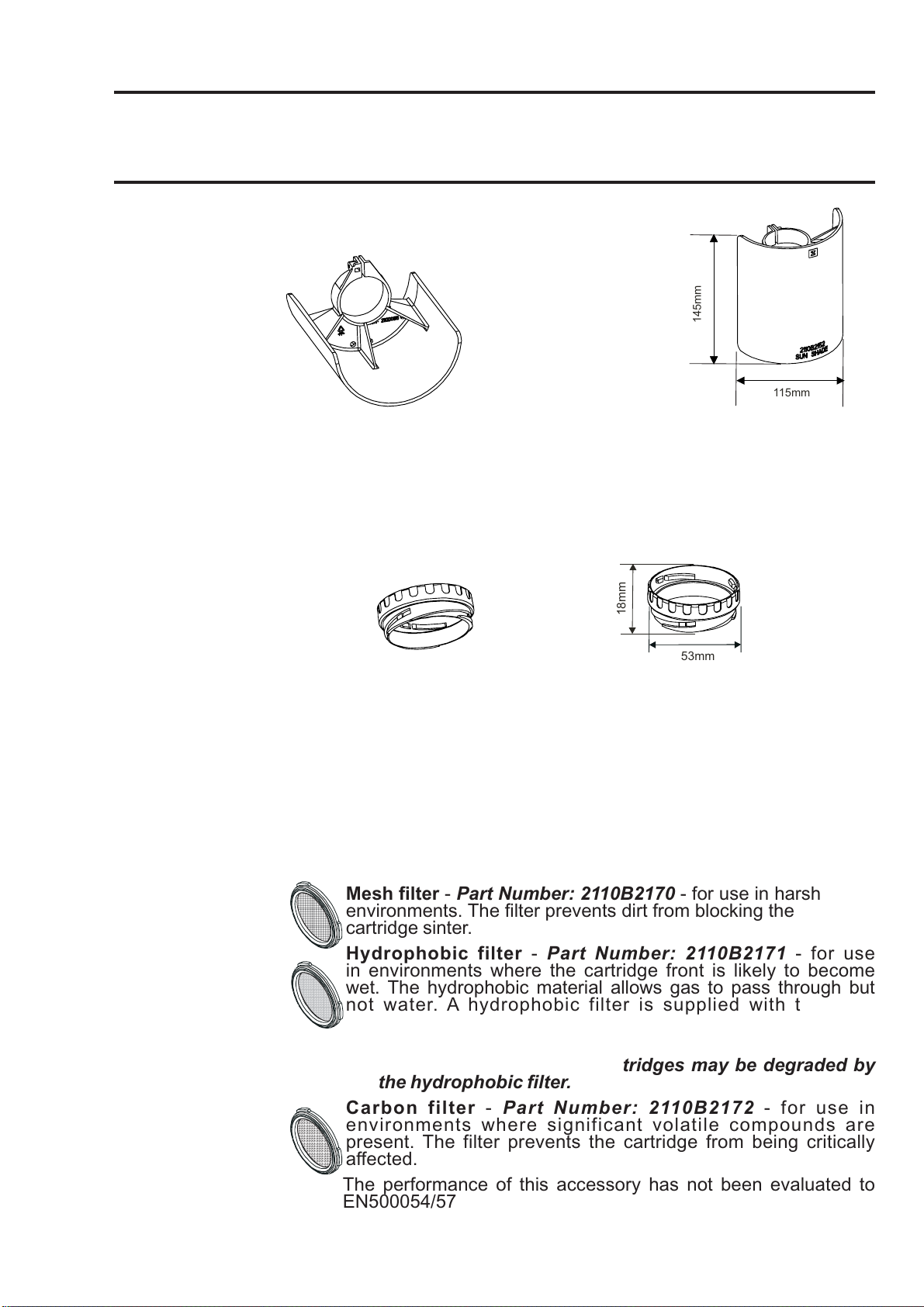
2.3.5 Sunshade
Part Number: 2110B2152
145mm
115mm
The Sunshade prevents excessive heating of the sensor by direct sunlight.
Conforms to CSA C22.2 No. 152 when fitted to the Certified Sensor with
specific cartridges installed. See specifications for details.
The performance of this accessory has not been evaluated to EN50054/57.
The sunshade is fitted to the sensor body by means of a clamp.
2.3.6 Oxygen Transducer Adaptor
18mm
53mm
The Oxygen Transducer Adaptor is supplied with the Oxygen cartridge
and is necessary because the depth of the Oxygen cartridge is more
than that of the other gas cartridges.
The adaptor is attached to the Certified Sensor by means of a bayonet
fitting. The Oxygen cartridge is fitted first and the sensor cap or accessory
is then fitted to the adaptor by means of a bayonet fitting.
2.3.7 Filters
One of three different types of filter accessory can be fitted to the Certified
Sensor in place of the rubber seal inside the sensor cap or accessory.
The three different types of filter available are:
Mesh filter - Part Number: 2110B2170 - for use in harsh
environments. The filter prevents dirt from blocking the
cartridge sinter.
Hydrophobic filter - Part Number: 2110B2171 - for use
in environments where the cartridge front is likely to become
wet. The hydrophobic material allows gas to pass through but
not water. A hydrophobic filter is supplied with the Flow
Housing and must be used when calibrating sensors fitted
with flammable gas cartridges.
Caution: The sensitivity of some cartridges may be degraded by
the hydrophobic filter.
Carbon filter - Part Number: 2110B2172 - for use in
environments where significant volatile compounds are
present. The filter prevents the cartridge from being critically
affected.
The performance of this accessory has not been evaluated to
EN500054/57
19
Page 20

MAN0604 Issue 04 Feb 04 Apex
2110M8030
3. INSTALLATION
The Apex system components can be used together in a variety of ways for different
installation requirements in a hazardous environment. For installations of certified
components also refer to the Control Drawings in Appendix B.
The following types of system installation are typical examples of those that can
be made:
• Apex Transmitter unit with a Certified Sensor locally mounted
at the Transmitter Unit and field wiring from the Transmitter
Unit to the system controller.
• Transmitter unit with a Certified Sensor mounted remotely
in a Certified Junction Box, with field wiring between the two
components, and from the Transmitter Unit to the system
controller.
This chapter describes how to:
• carry out the installation of a Transmitter Unit and Certified
Sensor
• install an Certified Junction Box accessory with
Certified Sensor, suitable for remote operation
• install a LonWorks Communications Board in a Transmitter
Unit
This is to enable the unit to be controlled and communicate over
a digital network, e.g. LonWorks.
Caution: Do not install a communications board into a UL or CSA certified
Transmitter Unit as approval for fitment is pending.
• install the system accessories
When fitting the system components consideration should be made regarding
potential gas leak sources, density of the gas to be detected, probability
of mechanical impacts and interference from other equipment and
apparatus.
For optimum performance the Transmitter Unit and Certified Sensor should
be installed in a location free from dust and direct sunlight. Sunshade
and weather protection accessories for the sensor are available when
operating in harsh external environments (see 3.4).
Refer to the relevant control system manual for external network
connection information (e.g. field wiring, etc.).
20
Page 21

MAN0604 Issue 04 Feb 04 Apex
2110M8030
3. INSTALLATION
Also see drawing 2110C8049 Outline Dimensions of Certified Transmitter,
Sensor & Accessories (available on request from Zellweger Analytics).
General Installation Guidelines
The following general points should be noted before any installation is carried
out.
• Read all the instructions before starting any of the
installation procedures.
• Identify a suitable location with a flat surface where the
Apex Transmitter Unit/Certified Junction Box can be
mounted.
• Identify external cable requirements and the necessary
cable/conduit entry ports to be used on the Apex
Transmitter Unit/Certified Junction Box.
• The Certified Sensor must always point downwards to
avoid collection of fluids and other materials on the face.
• When fitting components that are certified also refer to the
Control Drawings (see Appendix B).
The system components comply with the EMC requirements of EN50270. In
order to maintain compliance with this standard it is essential that the components
are installed correctly as detailed below. It is the responsibility of the installation
design authority to ensure that the electrical installation meets appropriate
standards.
1. The unit should not be electrically connected to electrically noisy (dirty)
metalwork or conductors. The case should be connected to a low noise
(clean) earth line via the screen on the field cabling.
2. The entire length of the field cabling connected to each unit should be fully
screened with the screen connected to a low noise earth.
3. The low noise earth line should only be connected to safety earth at a single
point. Star earthing arrangements minimise earth current crosstalk. Field
cabling shields should not be connected such that earth loops are produced.
4. The earth bonding arrangement must ensure that the maximum peak voltage
between the unit case earth and any field cable conductor is less than 350V.
Voltages in excess of this can cause permanent damage to the unit's RFI
protection filters.
5. The use of a single, screening cable for each gas detector ensures maximum
screening and minimum crosstalk. Cabling arrangements which use a single
cable for connecting field devices compromise screening, increase the
21
Page 22
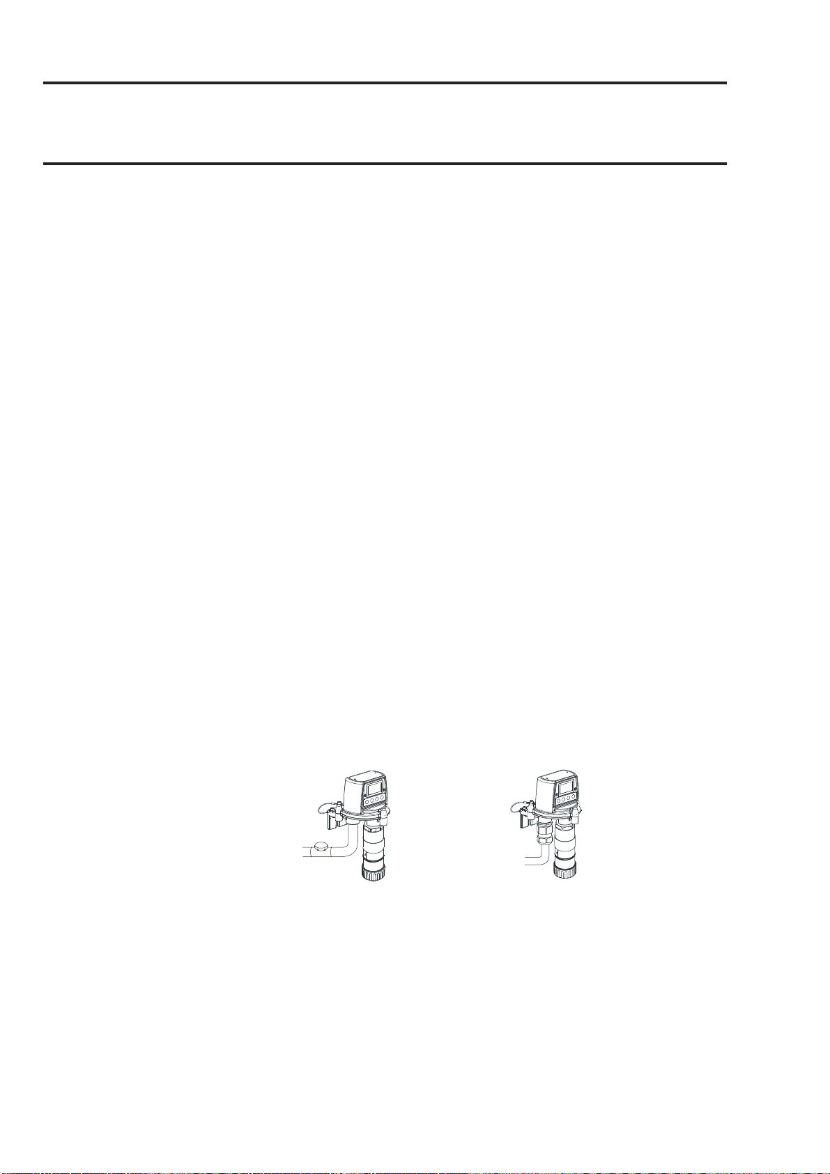
MAN0604 Issue 04 Feb 04 Apex
Apex Transmitter Unit
with Certified Sensor
(European
-style
installation)
2110M8030
3. INSTALLATION
potential for crosstalk and prevent implementation of true star earthing.
6. Any electrical interference induced onto the 4-20mA loop conductors by
the installation must be kept below the levels necessary to comply with
the general requirements of EN50270. In practice, this means that peak
noise currents induced on the current loop should be no greater than ±
0.25mA.
7. The 0V rail of the control card/system is often directly connected to one
side of the 4-20mA current sensing resistor. Electrical noise on such a rail
is therefore directly connected to the 4-20mA input. In order to avoid
additional noise being induced on the 0V rail, it should not be common
with the safety earth/ground which frequently carries a high level of electrical
noise.
8. The 24V supply should be free from large transients and fluctuations.
The type of cable used for field wiring between the Apex transmitter and control
equipment, and between the Apex transmitter and Apex sensor if mounted
remotely, should be selected to meet the environmental and hazardous area
requirements. The cable internal construction should be a of the screened, multicore, multi-stranded type. The terminals within the product will accept a maximum
conductor size of 2.5mm2 (14AWG). The recommended minimum conductor size
is 0.75mm2 (20AWG). The conductors should be sized to give a total power supply
loop resistance of less than 30 Ohms (ECC cartridge) or 16 0hms (Catalytic
cartridge). If remote mounting the sensor from the transmitter a 4-core, screened
cable with a minimum conductor size of 0.75mm2 (20AWG) is required.
3.1 TRANSMITTER UNIT AND CERTIFIED SENSOR
This installation consists of a Transmitter Unit with Certified Sensor locally mounted
at the Transmitter Unit together with field wiring.
Apex Transmitter Unit
with Certified Sensor
North America-style
(
installation)
The system components can be installed by a single technician.
This procedure describes how to:
• install a Transmitter Unit
• fit a Certified Sensor to the local Transmitter Unit
• connect up the Certified Sensor and field wiring
• configure the Transmitter Unit relay and alarm settings
• install a gas sensing cartridge into the Certified Sensor
22
Page 23
MAN0604 Issue 04 Feb 04 Apex
2110M8030
3. INSTALLATION
Refer to the General Installation Guidelines at the beginning of this chapter.
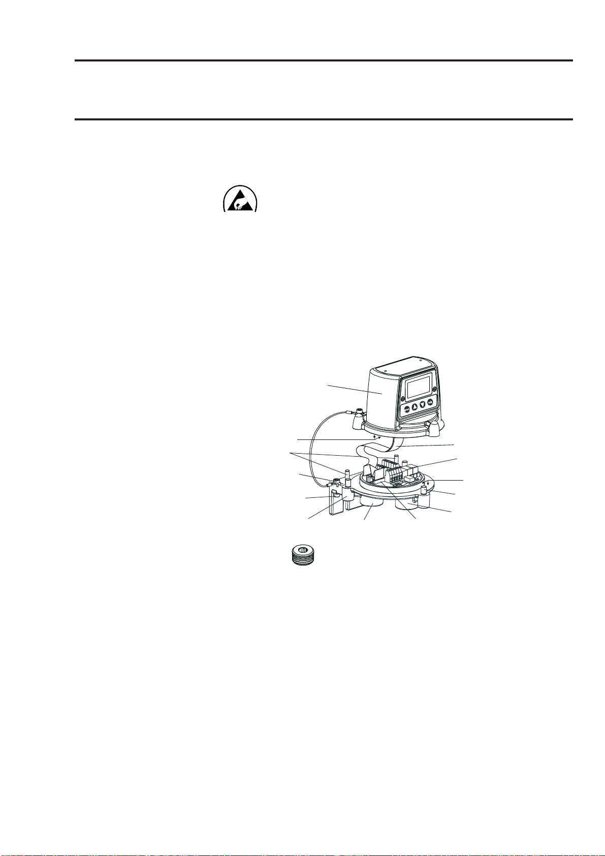
3.1.1 Installing the Transmitter Unit
Cautions:
1. Observe precautions for handling electrostatic
discharge sensitive devices.
2. Ensure that the Apex Transmitter Unit flamepath is not
damaged during this procedure. The flamepath is formed by the
mating surfaces of the Apex Transmitter Unit top and base (see
diagram).
(1) Isolate all associated power supplies and ensure that they remain OFF
during the installation procedure. Ensure a gas free atmosphere.
(2) Attach the Apex Transmitter Unit to the supporting structure.
Drill two mounting holes (68mm apart) and use the unit’s mounting slots in
the base with either two M10 bolts or a single 10mm U-bolt.
Unit top
Top retaining
cable
Flamepath
Locating
pins
Cable securing
screw
External
earth
Unit base
Cable / conduit
entry (2 off)
Cable/conduit entry sealing plug
(3) Detach the top of the Transmitter Unit.
Unscrew the three captive M8 bolts in the base. Support the top and let
the metal retaining cable, attaching the top to the base, hold the top. Take
care not to damage or strain the ribbon cable between the top and the
base.
(4) Fit and connect the field wiring.
ZIF
Ribbon cable
Interconnect
PCB
Flamepath
Captive bolt
(3 off)
Certified
Sensor mounting
point
See the subsequent wiring table and diagram. Use either:
23
Page 24

MAN0604 Issue 04 Feb 04 Apex
2110M8030
3. INSTALLATION
Conduit - using one or both of the 3/4 NPT conduit entries. Ensure that a
conduit sealing fitting is installed within 460mm of the enclosure on all
conduit runs.
Cable - using any suitable flameproof cable entry device certified as
Equipment to Directive 94/9/EC (ATEX).
Note: All unused cable/conduit entries must be sealed with a suitable certified
sealing plug (one plug is supplied).
Typical wiring arrangements to the Transmitter Unit are (with all cables
screened):
Single cable/conduit entry
Power 4-20mA Digital Comms Relays Cores used
21--3
22--4
22-610
222-6
2-2-4
Twin cable/conduit entries
Power 4-20mA Digital Comms Relays
2 2 (4 cores) - 6 (6 cores)
2 2 2 (6 cores) 6 (6 cores)
2 x power in - 2 x comms in (4 cores) 2 x power out - 2 x comms out (4 cores) -
More complex wiring schemes may need to use external Certified Junction
Boxes either because of cable/conduit entry capacity or because there
are more than two cable/conduit destinations.
3.1.2 Fitting the Certified Sensor
(1) Fit the Certified Sensor to the Transmitter Unit.
24
Page 25
MAN0604 Issue 04 Feb 04 Apex
2110M8030
3. INSTALLATION
Transmitter Unit
base
Certified Sensor
mounting point
Certified Sensor
Feed the sensor cable through the Certified Sensor mounting point at the
front of the Transmitter Unit base. Screw the sensor firmly into the mounting
point until it is fully home.
(2) Connect the sensor wiring.
See the following wiring table and diagram.
Terminal Function Colour Recommended
Number Wire Length
SK3
(Sensor)
SK4
(Comms
and
Power)
SK6
(Relays)
1 CAN_L White 40mm
2 CAN_H Green 40mm
3 +V Red 40mm
4 0V Black 40mm
5 Screen 40mm
1 NET1 60mm
2 NET2 60mm
3 Ground 50mm
4 4 - 20mA - 50mm
5 4 - 20mA + 50mm
6 0V 50mm
7 +24Vdc (18-32Vdc) 50mm
1 Fault 50mm
2 Fault common 50mm
3 Alarm 1 50mm
4 Alarm 1 common 50mm
5 Alarm 2 50mm
6 Alarm 2 common 50mm
G - Earth Green/Yellow
25
Page 26
MAN0604 Issue 04 Feb 04 Apex
2110M8030
3. INSTALLATION
Ground
SK4
Ground
SK3
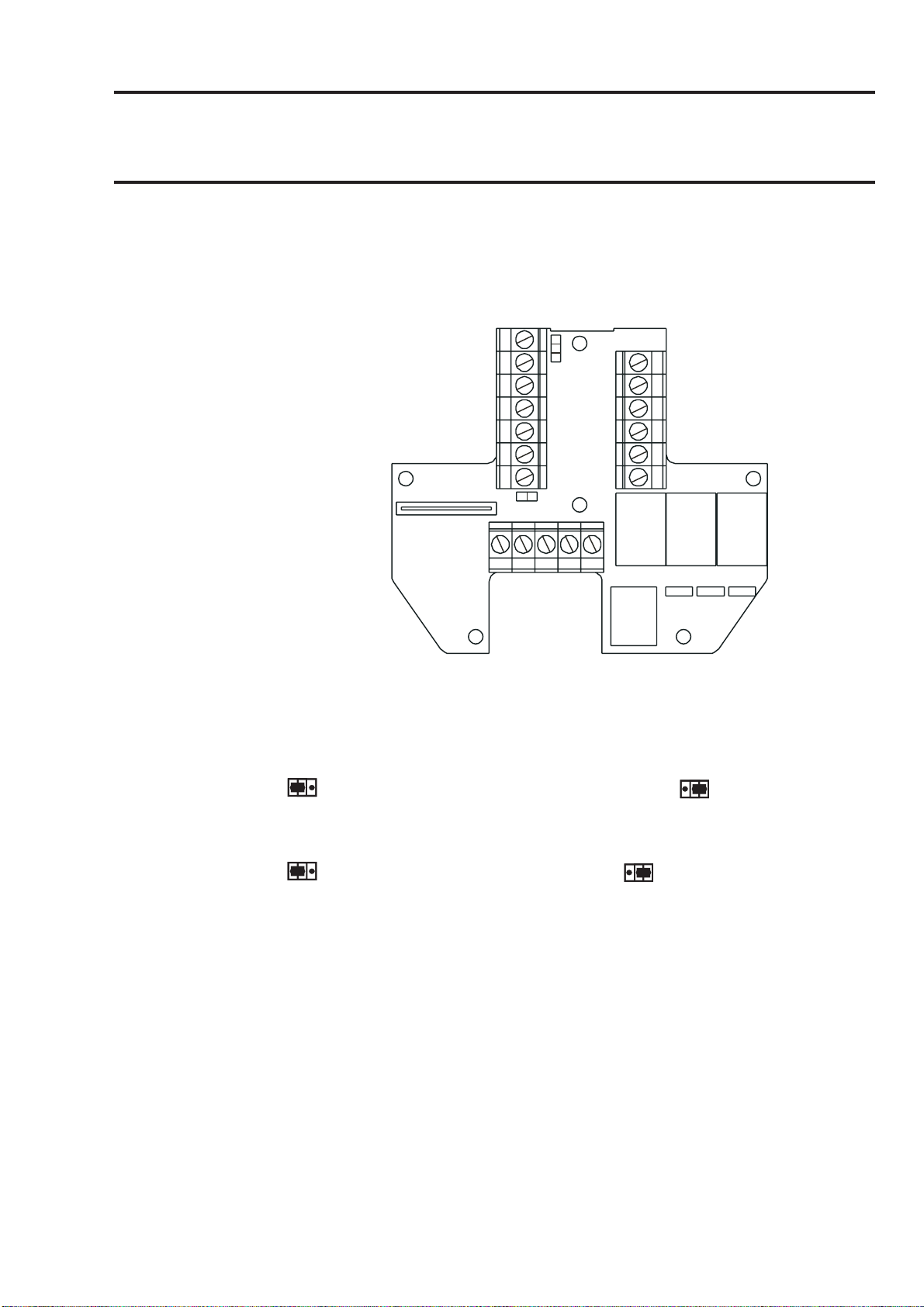
(3) Configure the Transmitter Unit if required.
SK6
Set the links on the Interconnect PCB for the required relay contact settings
and for the 4-20mA topology. See 3.1.4.
(4) Refit the top to the base.
Cautions:
1. Ensure that there is no moisture inside the unit before fitting the top.
2. Use only the captive bolts supplied, replacement with alternative
bolts will invalidate certification.
Follow the reverse of the removal procedure supporting the top. The top
should be positioned using the locating pins on the Apex Transmitter Unit
base and then lowered onto the base.
Ensure that the lid retaining cable and wiring is not trapped and the O-ring
in the top is correctly located.
Ensure that the ribbon cable is not twisted and is correctly positioned.
Check that there is no discernible gap between the top and the base.
Tighten the three captive M8 bolts to 5Nm (3.68 foot-pounds).
26
Page 27
MAN0604 Issue 04 Feb 04 Apex
2110M8030
3. INSTALLATION
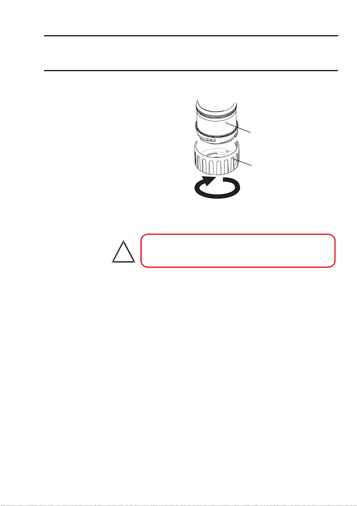
3.1.3 Installing the Gas Sensing Cartridge
(1) Remove the cap from the Certified Sensor body.
Sensor
body
Sensor
cap
Rotate the cap or accessory 1/4 turn in an anticlockwise direction to release
the bayonet fitting.
(2) Fit the gas sensing cartridge into the sensor body.
WARNING
!
Each cartridge is provided with a certificate of calibration (printed on the
reverse of the instruction sheet, Part No: 2110M8015, supplied with the
cartridge) that guarantees that the cartridge is calibrated and ready for
use. Before installing a cartridge check that the number on the cartridge
label matches the gas type and range for the function required.
Caution: Only cartridges with the following part numbers can be fitted
Note: Conforms to CSA C22.2 No. 152 only when fitted with specific cartridges.
See specifications for details.
Sensor Cartridges may contain corrosive solutions.
Dispose of according to local and national regulations.
to the Certified Sensor:
2110B30x0, 31x0, 32x0, 33x0, 34x0 series
2110B3700 - 2110B3999 range
Carefully plug the cartridge into the Certified Sensor body ensuring that
the cartridge tab lines up with the recess in the sensor body and push the
cartridge, without twisting, until it is fully home.
If the cartridge will not push fully home, re-check that the locating tab is
correctly aligned with the recess in the sensor body. Position the tab so it is
resting on the tab recess wall to the right or left of the tab recess and then
turn the cartridge until the tab drops into the recess.
27
Page 28
MAN0604 Issue 04 Feb 04 Apex
2110M8030
3. INSTALLATION
Caution: Do not force the cartridge as this may cause damage to the pins
of the connecting plugs. Twisting and pushing can bend the
pins and make the cartridge inoperative.
Socket (2 off)
Plug
(2 off)
Locating
tab
recess
Sensor body
Note: If fitting an Oxygen cartridge ensure that the Oxygen Transducer Adaptor
supplied with the Oxygen cartridge is fitted to the Certified Sensor body.
The adaptor is fitted to the sensor body via a bayonet fitting.
(3) Refit the cap to the Certified Sensor.
Reverse the removal procedure.
Sensor body
Locating
tab
Cartridge
Cartridge fitted to sensor
body
Sensor cap
(4) Check for correct operation of the system by carrying out the procedures
described in Chapter 4.
28
Page 29
MAN0604 Issue 04 Feb 04 Apex
2110M8030
3. INSTALLATION
3.1.4 Transmitter Unit Configuration
Caution: Do not change either Relay or 4-20mA link setting while unit is
powered up.
The following information specifies the unit configuration options.
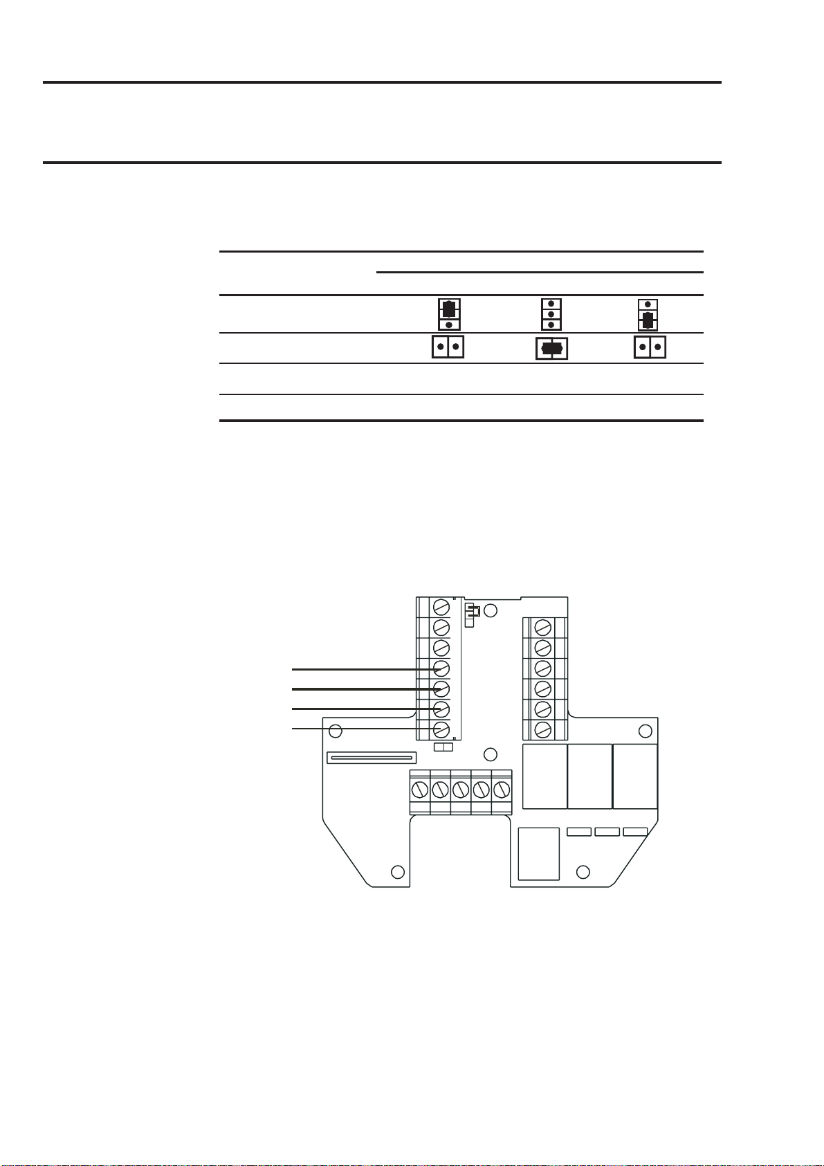
J4
J5
Fault Alarm Alarm
12
J1 J2 J3
J1 J2 J3
Relays
Links J1, J2 and J3 set the contact operation for the Fault, Alarm 1 and Alarm
2 relays respectively.
J1 (Fault relay)
Normally open. Normally closed
(default)
J2 and J3 (Alarm 1 and 2 Relays)
Normally open (default) Normally closed
Note: Relay contacts are rated at 100mA (min), 2A (max), 30Vdc non-
inductive*. HIGHER VOLTAGES MUST NOT BE USED
(* UL specification: 28Vdc, 1A)
29
Page 30
MAN0604 Issue 04 Feb 04 Apex
2110M8030
3. INSTALLATION
4-20mA loop
The summary table and subsequent diagrams identify the link and terminal settings
for 4-20mA loop options.
Link
J4
SK4
Terminal Isolated Source Sink
-
4 - 20mA loop topology
J5 -
- 4 4 - 20mA - 4 - 20mA - not used
- 5 4 - 20mA + not used 4 - 20mA +
Note: Total 4-20mA loop resistance should be less than 300 ohms.
Total power supply loop resistance should be less than 30 ohms (ECC
cartridge) or 16 ohms (catalytic cartridge).
Typical power consumption with relays active is 3.6W (ECC cartridge)
or 5.6W (catalytic cartridge).
Isolated Mode (4-wire)
SK4
4 - 20mA -
4 - 20mA +
0V
+24V dc
1
2
3
4
5
6
7
J4
30
J5
Page 31

MAN0604 Issue 04 Feb 04 Apex
2110M8030
3. INSTALLATION
Current Sink Mode (3-wire)
SK4
4 - 20mA +
0V
+24V dc
Current Source Mode (3-wire)
SK4
4 - 20mA -
0V
+24V dc
1
2
3
4
5
6
7
J5
1
2
3
4
5
6
7
J5
J4
J4
3.2 CERTIFIED JUNCTION BOX AND CERTIFIED SENSOR
This installation consists of a Certified Junction Box accessory with the Certified
Sensor locally mounted at the box together with field wiring.
31
Page 32

MAN0604 Issue 04 Feb 04 Apex
2110M8030
3. INSTALLATION
Apex Transmitter Unit
with Certified Sensor mounted
in Certified Junction Box
North America-style installation)
(
Apex Transmitter Unit
Certified Junction Box
with Certified Sensor
Apex Transmitter Unit
with Certified Sensor mounted
in Certified Junction Box
(European
Apex Transmitter Unit
-style installation)
o
Certified Junction Box
with Certified Sensor
The system components can be installed by a single technician. This procedure
describes how to:
• install a Certified Junction Box
• fit the Certified Sensor to the Certified Junction Box
• connect up the Certified Sensor and field wiring
• configure the Certified Junction Box
• install a gas sensing cartridge into the Certified Sensor
Refer to the General Installation Guidelines at the beginning of this chapter.
32
Page 33

MAN0604 Issue 04 Feb 04 Apex
2110M8030
3. INSTALLATION
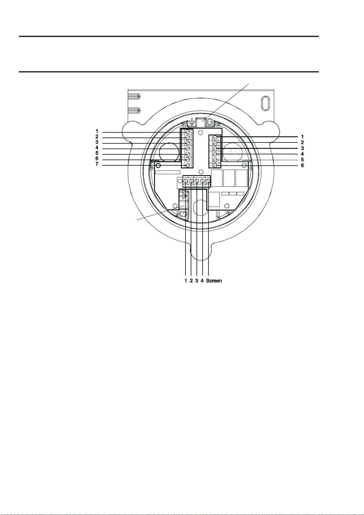
3.2.1 Installing the Certified Junction Box
Caution: Ensure that the Certified Junction Box flamepath is not damaged
during this procedure. The flamepath is formed by the mating
surfaces of the Certified Junction Box top and base (see
diagrams).
(1) Isolate all associated power supplies and ensure that they remain OFF
during the installation procedure. Ensure a gas free atmosphere.
Lid retaining
cable
Flamepath
Terminal block
(3 off)
External
earth
Cable / conduit
entry (2 off)
Cable entry
sealing
plug (1 off)
Certification label
Certified Junction
Box Top
Interconnect PCB
Flamepath
Captive bolt
(3 off)
Sensor
mounting point
(2) Attach the Certified Junction Box to the supporting structure.
Drill two mounting holes (68mm apart) and use the unit’s mounting slots
in the base with either two M10 bolts or a single 10mm U-bolt.
(3) Remove the Certified Junction Box lid.
Unscrew the three captive M8 bolts. The lid is retained by a metal retaining
cable attached to the base.
(4) Fit and connect the field wiring.
See the subsequent tables and diagram for wiring details. Use either:
33
Page 34

MAN0604 Issue 04 Feb 04 Apex
2110M8030
3. INSTALLATION
Conduit - using one or both of the ∫ NPT conduit entries. Ensure that a
conduit sealing fitting is installed within 18" of the enclosure on all conduit
runs.
Cable - using any suitable flameproof cable entry device certified as
Equipment to Directive 94/9/EC (ATEX).
Notes:
1. All unused cable/conduit entries must be sealed with a certified sealing
plug (one plug is supplied fitted).
2. For a multi-sensor system using a network loop, both cable/conduit entries
are used, one bringing the loop connections in and the other taking them
out of the box. Remove the fitted certified sealing plug from the spare
cable/conduit entry.
3.2.2 Fitting the Certified Sensor
(1) Fit the Certified Sensor to the Certified Junction Box.
Certified Junction
Box base
Certified Sensor
mounting point
Certified Sensor
Pass the sensor connecting cable through the sensor mounting point and
then screw the sensor firmly into the sensor mounting point until it is fully
home.
(2) Connect the sensor wiring.
See the following diagram and table for wiring details.
34
Page 35

MAN0604 Issue 04 Feb 04 Apex
2110M8030
3. INSTALLATION
Terminal/Number Function Colour
SK1 1 CAN_L White
SK2
SK3
SK4 1 Screen * -
G - Earth Green/Yellow
* Only connect cable screens to these terminals if they are isolated at the remote
end.
2 CAN_H Green or Blue
3 +V Red
4 0V Black
5 Not used -
2 Screen * -
Note: Three sensor wiring terminal blocks are provided (SK1, SK2 SK3), any
two can be used.
SK2 SK1
1
2
3
4
5
5
4
3
2
1
2
1
J1
SK4
Internal earth
12345
SK3
(3) Configure the Certified Junction Box if required.
Set the link on the Interconnect PCB for the required Controller Area network
(CAN) setting. See 3.2.4.
(4) Refit the top to the Certified Junction Box base.
35
Page 36

MAN0604 Issue 04 Feb 04 Apex
2110M8030
3. INSTALLATION
Cautions:
1. Ensure that there is no moisture inside the Certified Junction Box
before fitting the lid.
2. Use only the captive bolts supplied, replacement with alternative
bolts will invalidate certification.
The top should be located using the locating pins on the Certified
Junction Box base and then lowered onto the base. Ensure that the lid
retaining cable and/or wiring are not trapped and the O-ring in the top is
correctly located. Check that there is no discernible gap between the
top and the base. Tighten the captive M8 bolts to 5Nm (3.68 footpounds).
3.2.3 Installing the Gas Sensing Cartridge
(1) Remove the cap from the Certified Sensor body.
Sensor
body
Sensor
cap
Rotate the cap or accessory 1/4 turn in an anticlockwise direction to release
the bayonet fitting.
(2) Fit the gas sensing cartridge into the sensor body.
WARNING
!
Sensor Cartridges may contain corrosive solutions.
Dispose of according to local and national regulations.
Each cartridge is provided with a certificate of calibration (printed on the
reverse of the instruction sheet, Part No: 2110M8015, supplied with the
cartridge) that guarantees that the cartridge is calibrated and ready for
use. Before installing a cartridge check that the number on the cartridge
label matches the gas type and range for the function required.
Caution: Only cartridges with the following part numbers can be fitted to
the Certified Sensor:
2110B30x0, 31x0, 32x0, 33x0, 34x0 series
2110B3700 - 2110B3999 range
36
Page 37

MAN0604 Issue 04 Feb 04 Apex
2110M8030
3. INSTALLATION
Note: For remote CSA Certified Sensor installations combustible cartridges in
the range of part numbers 2110B3700 to 2110B3799 MUST NOT BE
FITTED.
Carefully plug the cartridge into the Certified Sensor body ensuring that
the cartridge tab lines up with the recess in the sensor body and push the
cartridge, without twisting, until it is fully home.
If the cartridge will not push fully home, re-check that the locating tab is
correctly aligned with the recess in the sensor body. Position the tab so it
is resting on the tab recess wall to the right or left of the tab recess and
then turn the cartridge until the tab drops into the recess.
Caution: Do not force the cartridge as this may cause damage to the pins
of the connecting plugs. Twisting and pushing can bend the
pins and make the cartridge inoperative.
Socket (2 off)
Plug
(2 off)
Locating
tab
recess
Sensor body
Note: If fitting an Oxygen cartridge ensure that the Oxygen Transducer Adaptor
supplied with the Oxygen cartridge is fitted to the Certified Sensor body.
The adaptor is fitted to the sensor body via a bayonet fitting.
(3) Refit the cap to the Certified Sensor.
Reverse the removal procedure.
Sensor body
Locating
tab
Cartridge
37
Cartridge fitted to sensor
body
Sensor cap
Page 38

MAN0604 Issue 04 Feb 04 Apex
2110M8030
3. INSTALLATION
(5) Check for correct operation of the system by carrying out the procedures
described in Chapter 4.
3.2.4 Certified Junction Box Configuration
The following information specifies the Certified Junction Box configuration options.
Controller Area Network (CAN )Termination Link - J1
Terminated
Unterminated (default)
Note: Leave the link in the Unterminated position.
3.3 LONWORKS COMMUNICATIONS BOARD
The LonWorks Communications Board can be installed in the Transmitter Unit
by a single person. It is fitted into the top of the unit to form part of theMain PCB
assembly.
Note: Do not install a communications board into a UL or CSA certified Transmitter
Unit as approval for fitment is pending.
Refer to the General Installation Guidelines at the beginning of this chapter.
Fitting the board should be carried out by a qualified technician.
Electrical interconnections for the communications board are made at the same
time as mechanical installation by means of plugs attached to the communications
board. These plugs mate with existing sockets on the main PCB fitted to the Apex
Transmitter Unit lid.
Once the board is fitted any external LonWorks network wiring required is connected.
Plug
(2 off)
LonWorks board
Mounting pillar (4 off)
Earth lead
38
Page 39

MAN0604 Issue 04 Feb 04 Apex
2110M8030
3. INSTALLATION
Note: The board is supplied with the mounting pillars fitted to it.
This procedure describes how to:
• remove the Transmitter Unit top
• remove the Main PCB assembly from the top
• fit the LonWorks Communication Board to the Main PCB
• refit the Main PCB assembly into the top
• connect the LonWorks network wiring
• refit the Transmitter Unit top
• operational check and binding the LonWorks Communication
Board to the network
Refer to the General Installation Guidelines at the beginning of this chapter.
3.3.1 Removing the Transmitter Unit top
Cautions:
1. Observe precautions for handling electrostatic
discharge sensitive devices.
2. Ensure that the Apex Transmitter Unit flamepath is not
damaged during this procedure. The flamepath is formed by the mating
surfaces of the Apex Transmitter Unit top and base (see diagram).
(1) Isolate all associated power supplies and ensure that they remain OFF during
this procedure. Ensure a gas free atmosphere.
(2) Disconnect from the Transmitter Unit base the wire retaining cable fitted
between the top and the base.
Unscrew and remove the single M6 hexagon screw that secures the cable
to the base.
39
Page 40

MAN0604 Issue 04 Feb 04 Apex
2110M8030
3. INSTALLATION
Unit top
Top retaining
cable
Flamepath
Locating
pins
Cable securing
screw
External
earth
Unit base
Cable / conduit
entry (2 off)
ZIF
Ribbon cable
Interconnect
PCB
Flamepath
Captive bolt
(3 off)
Certified
Sensor mounting
point
Cable entry sealing plug
(3) Detach the top of the Transmitter Unit.
Unscrew the three captive M8 bolts underneath the base. Lift the top clear
of the locating pins. Take care not to damage or strain the ribbon cable
connecting the top and the base.
Support the top and ensure that it is supported whilst the next step is
carried out.
(4) Unlatch the ribbon cable Zero Insertion Force (ZIF) connector on the
Interconnect PCB.
Grip the ends of the ZIF and pull it vertically upwards until it is felt to stop
and the ribbon cable is loose.
(5) Pull the ribbon cable clear.
Remove the top and take to a workshop area.
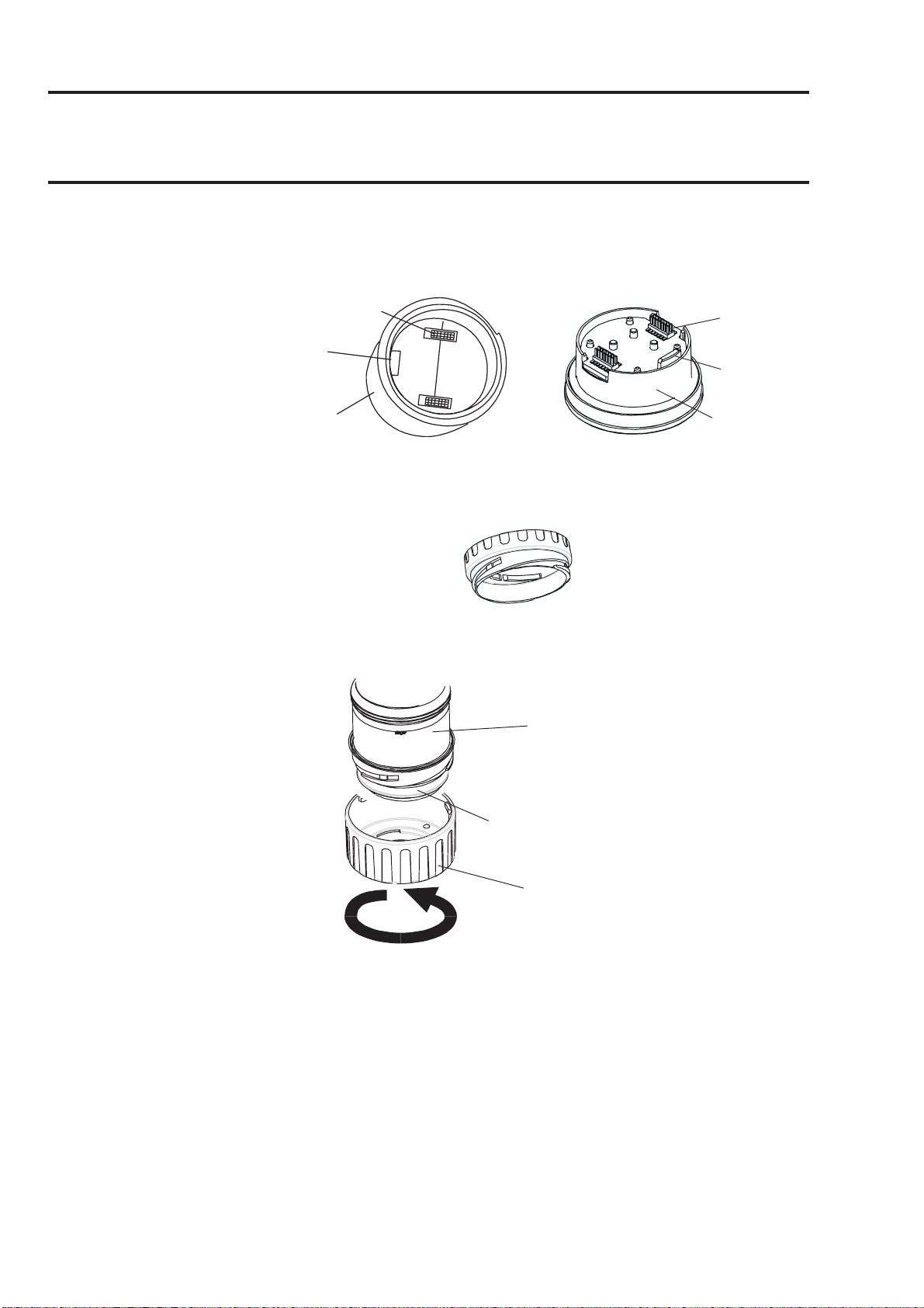
3.3.2 Removing the Main PCB assembly from the top
(1) Place the top with the certificate face down on a flat surface.
This provides access to the components inside the top.
40
Page 41

MAN0604 Issue 04 Feb 04 Apex
2110M8030
3. INSTALLATION
Main PCB
Potted assembly
PCB
PCB
baffle
baffle
(2) Remove the PCB Baffle from the Transmitter Unit top.
Unscrew and remove the two PCB Baffle securing screws.
(3) Disconnect the flying lead plug and socket connecting the Main PCB Potted
assembly to the top.
(4) Slide the Main PCB Potted assembly out of the Apex Transmitter Unit top.
Ribbon
cable
PCB baffle
securing screw
(2 off)
3.3.3 Fitting the LonWorks Communication Board to the Main PCB
Main PCB
Flying lead
Main PCB
Potted assembly
(1) Place the Main PCB Potted assembly on a flat surface with the flying lead
and plug on top.
Push the flying lead to one side so that there is clear access to the Main
PCB.
(2) Remove the LonWorks Communication Board from its antistatic bag.
(3) Position the Communication Board over the Main PCB.
Ensure the mounting pillars point downwards. Check that the two plugs on
the Communication Board are correctly aligned with the sockets on the
Main PCB and the mounting pillars are aligned with their mounting holes.
(4) Carefully press the Communication Board down evenly onto the Main PCB.
41
Page 42

MAN0604 Issue 04 Feb 04 Apex
2110M8030
3. INSTALLATION
Ensure that the pillars locate in their mounting holes and the electrical
plugs are fully home.
Hole for communication
Flying lead
board mounting pillar
Ribbon
cable
Main PCB
Sockets
(5) Reconnect the flying lead plug and socket connecting the Main PCB to
the top.
3.3.4 Refitting the Main PCB Assembly into the Top
(1) Refit the Main PCB Potted assembly with Communication Board into the
top.
Reverse the removal procedure. The assembly should be fitted so that
the communications board is on the same side as the LCD display with
the ribbon cable at the top.
(2) Refit the PCB Baffle.
Caution: When refitting the parts into the top take care not to damage the
flying lead plug assembly wires.
Ensure that the vertical part of the baffle goes between the Main PCB and
the flying lead (see diagram).
Push the Communication Board earth lead through the top middle hole in
the baffle.
Secure the earth lead under one of the two baffle securing screws. Tighten
the screws to 1.0Nm (0.74 foot-pounds).
Potted assembly
42
Page 43

MAN0604 Issue 04 Feb 04 Apex
2110M8030
3. INSTALLATION
Top, middle
PCB baffle
hole
3.3.5 Connecting the LonWorks Network Wiring
Main PCB
Flying lead
Main PCB
Potted assembly
(1) Fit and connect the communication network field wiring to SK4 in the
base of the Transmitter Unit.
Refer to the table and diagram for wiring details. Use either:
Conduit - using one or both of the 3/4 NPT conduit entries. Ensure that
a conduit sealing fitting is installed within 18" of the enclosure on all
conduit runs.
Cable - using any suitable flameproof cable entry device certified as
Equipment to Directive 94/9/EC (ATEX).
Note: All unused cable/conduit entries must be sealed with a suitable certified
sealing plug (one plug is supplied with the Apex Transmitter Unit).
Terminal number Function Min. length of cable from entry
point
SK4 1 NET1 60mm
(Comms 2 NET2 60mm
& Power)
3 Ground 60mm
43
Page 44

MAN0604 Issue 04 Feb 04 Apex
2110M8030
3. INSTALLATION
Note: Three terminal blocks are provided, any two can be used.
1
2
3
SK4
3.3.6 Refitting the Transmitter Unit Top
(1) Support the top.
Ensure that it is supported whilst the next step is carried out.
(2) Reconnect to the Transmitter Unit base the wire retaining cable fitted
between the top and the base.
Fit and tighten the single M6 hexagon screw that secures the cable to the
base. Tighten the M6 screw to 3Nm (2.21 foot-pounds). Remove the
support for the top and let the top down gently until it is supported by the
retaining cable.
(3) Reconnect the ribbon cable into the ZIF connector on the Interconnect
PCB in the base of the Transmitter Unit.
Follow the reverse of the removal procedure ensuring that the ribbon is
not twisted and is correctly centred relative to the ZIF connector before
insertion. Make sure that the ribbon cable contacts face in the same direction
as the arrow on the following diagram. Push the latch on the connector
down evenly until it is fully engaged.
44
Page 45

MAN0604 Issue 04 Feb 04 Apex
2110M8030
3. INSTALLATION
(4) Refit the top to the Transmitter Unit base.
Cautions:
1. Ensure that there is no moisture inside the unit before fitting the top.
2. Use only the captive bolts supplied, replacement with alternative
bolts will invalidate certification.
The top should be located using the locating pins on the Apex base and
then lowered onto the base. Ensure no wires are trapped and the O-ring
in the top is correctly located. Check that there is no discernible gap between
the top and the base.
Tighten the captive M8 bolts to 5Nm (3.68 foot-pounds).
(5) Check for correct operation of the system by carrying out the procedures
described in the following section.
3.3.7 Operational Check
After installing the Communication Board and connecting the communication
network wiring it is necessary to check that the Apex Transmitter Unit, Certified
Sensor and Communication Board are working correctly together and also bind
the equipment, which now acts together as a node, to the communication network.
(1) Power-up the Transmitter Unit.
(2) Check that the Transmitter Unit completes its start-up sequence
successfully.
The Gas Reading should be displayed. Refer to the Fault Diagnosis sub-
section in Chapter 4 if an error message is displayed.
(3) Press the esc button on the front panel.
45
Page 46

MAN0604 Issue 04 Feb 04 Apex
2110M8030
3. INSTALLATION
The Main Menu is displayed.
Main Menu
Calibration Menu
Configuration Menu
Display Menu
History Log Menu
Change Passwords Menu
Reset Passwords
(4) Select (highlight) the Configuration Menu option.
Use the up/down keys.
(5) Press the ok button.
(6) Enter the current Level 2 password.
The Configuration Menu is displayed.
Configuration Menu
Change Cartridge
Configure 4-20mA
Configure Relays
Configure Alarms
Configure Digital
Select Language
Configure Backlight
(7) Select (highlight) the Configure Digital option.
(8) Press the ok button.
Use the up/down keys.
The Configure Digital menu is shown displaying information similar to
the following.
Configure Digital
Network Type: LonWorks
Connection Type: FTT-10
Node Id: 00A176094600
Node Address: N/A
Baud Rate: 78.0kbit/s
Node S/W Ver: 1.0
Assert Service PIN
For a full explanation of the information see Chapter 4.
(9) Select the Assert Service PIN option.
(10) Press the ok button.
This binds the node to the network.
The display automatically returns to the Configuration Menu.
(11) Press the esc button twice
This returns to the Gas Reading display via the Main Menu.
3.4 ACCESSORIES
All the accessories except for the Sunshade and filter are fitted to the Certified
46
Page 47

MAN0604 Issue 04 Feb 04 Apex
2110M8030
3. INSTALLATION
Sensor in the same way.
To fit a filter see the filter replacement instructions given in Chapter 5.
For the dimensions of the accessories see Chapter 2.
3.4.1 Flow Housing, Weather Protection, Collecting Cone
To fit the Flow Housing, Weather Protection, Collecting Cone accessories carry
out the following procedure.
(1) Remove the Certified Sensor cap.
Sensor
body
Sensor
cap
Rotate the cap in an anticlockwise direction by 1/4 turn to release the
bayonet fitting and pull off.
(2) Remove the rubber seal or filter from the sensor cap.
Lug location
Rubber seal
Filter
The rubber seal or filter is held in place in the cap by its three lugs. Carefully
prise the rubber seal or filter free from the lug location points in the cap or
accessory.
47
Page 48

MAN0604 Issue 04 Feb 04 Apex
2110M8030
3. INSTALLATION
(3) For the Collecting Cone only fit the cone onto the supplied housing.
The Collecting Cone is supplied as a kit of two parts that clip together.
(4) Fit the rubber seal/filter to the accessory.
Ensure that the rubber seal or filter is correctly installed in the accessory
the correct way round with the three lugs closest to the front face of the
accessory and correctly engaged in the locators.
(5) Fit the accessory onto the Certified Sensor body.
Reverse the cap removal procedure. The diagram shows the Flow Housing
accessory fitted to the Certified Sensor.
Certified
Sensor
Flow
Housing
3.4.2 Sunshade
The sun shade can be used with other accessories in the range such as the Flow
Housing, Weather Protection and Collecting Cone, but should be attached before
any other accessories are fitted, or after their removal.
To fit the Sunshade accessory carry out the following procedure.
(1) Remove the Certified Sensor cap or accessory.
48
Page 49

MAN0604 Issue 04 Feb 04 Apex
2110M8030
4. OPERATION
The Apex gas measuring system is controlled from the Transmitter Unit via a
menu system, displayed on an LCD screen, and a set of control buttons.
This chapter provides operational information about the following:
• Display and control buttons
• Start-up
• Passwords
• Menus
• User Tasks
• Fault diagnosis
• System Calibration
• Binding the Communications Board to the Network
If an optional digital communications board is fitted in the Transmitter Unit, e.g.
LonWorks, then control can also be achieved from a remote location.
4.1 DISPLAY AND CONTROL BUTTONS
k
o
esc
LCD screen
Control buttons
49
Page 50

MAN0604 Issue 04 Feb 04 Apex
2110M8030
4. OPERATION
4.1.1 LCD screen
The screen provides a graphical user interface that, during normal operation,
displays gas reading information. It also displays information about the system to
the user, via a password protected hierarchical system of menus, together with
system fault and information messages.
Caution: Gas events occurring whilst in menus are not reported locally.
4.1.2 Control buttons
The four buttons on the front panel below the LCD screen have the following
functions:
(esc) is used to exit/cancel the current screen/option and return to the
previous screen/option.
(up) is used to move upwards through the menu lists and to select (highlight)
a required menu option. It is also used to increment displayed values.
(down) is used to move downwards through the menu lists and to select
(highlight) a required menu option. It is also used to decrement displayed
values.
(ok) is used to execute/acknowledge the chosen item.
The buttons are also used to enter the current password when required to access
different menu levels (see 4.3 and 4.4).
Note: If a user response using the buttons is not made to a required menu
action, e.g. change/accept a displayed setting value, then the system waits
for approximately 10 minutes before the process is aborted and the unit
reverts to normal operation with the display showing the normal Gas
Reading screen.
If a value had been displayed and not changed within the timeout period
the system reverts to the status quo and uses the previously stored setting.
50
Page 51

MAN0604 Issue 04 Feb 04 Apex
2110M8030
4. OPERATION
4.2 START-UP
Switch on the power supply to the Apex Transmitter Unit.
With a correctly installed Certified Sensor the following information is shown
sequentially on the LCD screen:
ZELLWEGER
ANALYTICS
INITIALISING
0
CONNECTING
The Transmitter Unit initially waits for the Certified Sensor to stabilise, during
which period the 4-20mA output is inhibited (2mA). Wait for 15 minutes to ensure
sensor stabilisation has occurred before continuing.
If the sensor does not stabilise during the initialisation period (15 minutes), one of
the fault (F) or warning (W) alarm messages shown in Section 4.6 is displayed.
When the Certified Sensor stabilises, the LCD screen shows the current Gas
Reading together with the gas identity, full scale, and the units of
measurement.”
Note: If the current Gas Reading exceeds full scale the displayed
reading will be replaced with ’ >>>>’.”
This information is also transmitted on the 4-20mA output and optionally on the
digital network if a communications board is fitted in the Transmitter Unit.
Note: If the Transmitter Unit has a LonWorks Communications Board fitted then
the unit will, at some stage, need to be bound to the LonWorks network.
To do this carry out the LonWorks binding procedure described at the end
of this chapter.
CO 100 ppm
4.3 PASSWORDS
Caution: Always store passwords in a secure place. Do not let
unauthorised users access to them.
The different parts of the high-level menu structure are protected from different
levels of user by assigning a set of three different passwords.
The three password levels correspond to the following types of system user:
51
Page 52

MAN0604 Issue 04 Feb 04 Apex
2110M8030
4. OPERATION
• Level 1 System operator
• Level 2 System technician
• Level 3 System administrator
For example the Level 1 Password provides a system operator with access to
day-to-day system operations, e.g. resetting alarms, checking the number of
hours to the next Certified Sensor calibration, etc.
Level 2 Password could be assigned to a technician who needs to carry out
more difficult operations such as calibrating the Certified Sensor.
Level 3 Password is for the system administrator to initially set and subsequently
change passwords.
Once the three levels of password are specified then they are assigned to users
by the system administrator depending on their access authority.
Each password consists of a sequence of control button presses.
When prompted during menu use, the user enters the current four-digit password
required by pressing the four buttons in the correct sequence.
The entered password is represented on the LCD screen using asterisk
characters (*).
Notes:
1. The last keystroke is not displayed on the screen. If the password is correct
then the menu action previously selected is implemented immediately. If it
is not correct the asterisks are cleared and the user must enter the correct
password to proceed.
2. The default password supplied when the unit is first delivered is entered by
pressing the (ok, up, down and down) buttons in
sequence. This provides initial access to all of the menus.
The password level hierarchy allows the following:
• Functions available at Level 1 can also be accessed by using
the Level 2 or Level 3 passwords.
• Functions available at Level 2 can also be accessed by using
the Level 3 password. They cannot be accessed by Level 1.
• Functions available at Level 3 can only be accessed by using
the Level 3 password. They cannot be accessed by Level 1
or Level 2.
Note: After changing, the three passwords can also be reset to the default value.
Resetting all the passwords can only be carried out by the system
administrator (see 4.3.2).
4.3.1 Setting/changing passwords
This combined procedure describes how to initially set passwords and how to
52
Page 53

MAN0604 Issue 04 Feb 04 Apex
2110M8030
4. OPERATION
subsequently change them.
(1) Power-up the system.
Wait for the Gas Reading display to stabilise.
(2) Press the esc button.
The Main Menu is displayed.
Main Menu
Calibration Menu
Configuration Menu
Display Menu
History Log Menu
Change Passwords Menu
Reset Passwords
(3) Navigate to the Change Passwords Menu option.
Use the (up/down) keys.
(4) Press ok.
(5) Enter the current Level 3 password.
Use the buttons on the front panel. If setting passwords for the first time
after unit delivery or password reset, enter the default password by pressing
the (ok, up, down and down) buttons in sequence.
Passwords are shown using asterisks (*) on the LCD.
The Change Passwords Menu is then displayed.
Change Passwords Menu
Level 1 Password
Level 2 Password
Level 3 Password
(6) Navigate to the password level option to be changed.
Use the (up/down) keys.
(7) Press ok.
The following screen is displayed:
Level 1 Password
Enter Old Password
This example shows the Level 1 Password screen. The screens for
53
Page 54

MAN0604 Issue 04 Feb 04 Apex
2110M8030
4. OPERATION
Levels 2 and 3 are similar.
(8) Enter the current password for the chosen level.
Use the buttons on the front panel. If setting the password for the first time
after unit delivery or password reset, enter the default password by pressing
the (ok, up, down and down) buttons in sequence.
Passwords are shown using asterisks (*) on the LCD.
The following screen is displayed:
Level 1 Password
Enter New Password
(9) Enter the new password .
The following screen is displayed:
Level 1 Password
ReEnter New Password
(10) Enter the new password again .
The following screen is displayed:
Level 1 Password
Success! OK:Continue
(11) Press ok.
The display returns to the Change Passwords Menu.
Follow the procedure to set/change another password or press esc to
return to the Main Menu.
Note: If the wrong password is entered at the prompt during step 10 the following
screen is displayed:
Level 1 Password
Failure! OK:Continue
(1) Press ok.
The display returns to the Change
Passwords Menu.
(2) Repeat the procedure re-entering the
54
Page 55

MAN0604 Issue 04 Feb 04 Apex
2110M8030
4. OPERATION
correct password.
4.3.2 Password reset
The Reset Passwords option allows the system administrator to reset all the
passwords back to the default password supplied when the unit is first delivered,
i.e. (ok, up, down and down). This provides initial access to all
of the menus.
To reset the access passwords to the default value carry out the following procedure:
(1) Power-up the system.
Wait for the Gas Reading display to stabilise.
(2) Press the esc button.
The Main Menu is displayed.
Main Menu
Calibration Menu
Configuration Menu
Display Menu
History Log Menu
Change Passwords Menu
Reset Passwords
(3) Navigate to the Reset Passwords option.
Use the up/down keys.
(4) Press ok.
(5) At the prompt enter the following sequence of 8 keystrokes:
(up, down, ok, esc, esc, ok, down, up)
All the passwords are reset to their default value and the display returns to
the Main Menu.
4.4 MENUS
Menus are used to implement control of the Transmitter Unit.
The system Main Menu is accessed by pressing the esc button at the Gas
Reading display.
55
Page 56

MAN0604 Issue 04 Feb 04 Apex
2110M8030
4. OPERATION
Main Menu
Calibration Menu
Configuration Menu
Display Menu
History Log Menu
Change Passwords Menu
Reset Passwords
The Main Menu provides access to the primary tasks that are required when
setting-up and controlling the Transmitter Unit and Certified Sensor. The following
diagram summarises the menu hierarchy and options.
Calibration Menu
Gas Calibrate
Gas Challenge
4-20 mA Set Zero
Force 4-20mA
Force Relays
Force Digital
Configuration Menu
Change Cartridge
Configure 4-20mA
Configure Relays
Configure Alarms
Configure Digital
Main Menu
Calibration Menu
Configuration Menu
Display Menu
History Log Menu
Change Passwords Menu
Reset Passwords
Select Language
Configure Backlight
History Log Menu
View History Log
Reset History Log
Display Menu
Reset Alarms, Faults
Calibration Info
Current Config
Change Passwords Menu
Level 1 Password
Level 2 Password
Level 3 Password
The subsequent subsections describe each of the main menu options in turn and
show, using a flowchart format, how to access and implement their sub-options.
56
Page 57

MAN0604 Issue 04 Feb 04 Apex
2110M8030
4. OPERATION
The following symbols are used on the flowchart diagrams:
Gas Calibrate
Zero Calibration screen
Zero Gas
Calibrating
Success?
Use up/down
buttons
Sub-menu option selected.
Sub-menu action.
User action.
System process.
Decision.
Comment/instruction.
Button press.
4.4.1 Calibration Menu
Caution: The calibration procedure should only be performed by qualified
personnel.
Caution: "If "Yes" is selected for the "Span Calibrate?" option, the span
calibration must be completed successfully. Failure to do so will
result in the unit signaling a "Calibration Needed" fault.
Calibration Menu
Gas Calibrate
Gas Challenge
4-20 mA Set Zero
Force 4-20mA
Force Relays
Force Digital
The Calibration Menu allows settings for the Transmitter Unit to be made, e.g.
relay operation, and also settings for the Certified Sensor, e.g. gas calibrate.
This menu is protected by a Level 2 password.
57
Page 58

MAN0604 Issue 04 Feb 04 Apex
2110M8030
4. OPERATION
Gas Calibrate Calibration Menu
This option calibrates the Certified Sensor zero gas point and the span setting
point (see 4.7 for details of how to carry out this procedure).
Gas Calibrate
ok
Span Calibration screen
Zero Calibration screen
Zero Gas
ok
Calibrating
Success?
Yes
ok
Span calibration?
Yes
ok
No
No
Fault
diagnosis
Calibration
Menu
Set Span
Concentration
(ppm)
ok
Apply Gas
ok
Calibrating
Success?
Yes
ok
Calibration Menu
No
Use up/
down
buttons
Fault
diagnosis
Note: Depending on the type of gas cartridge fitted to the sensor, a choice of
two calibration gases may be displayed during Span Calibration,
e.g. C7H8 has the options C7H8 and CH4 as choices. If so choose the one
that will be used for calibration and press ok to continue.
58
Page 59

MAN0604 Issue 04 Feb 04 Apex
2110M8030
4. OPERATION
Gas Challenge Calibration Menu
Cautions:
1. Ensure that the area around the sensor is gas free before exiting
the Gas Challenge mode.
2. Upon leaving gas challenge mode, all outputs return to their active
states (from inhibited). Ensure that values have returned to zero to
avoid extraneous alarms.
Provides the means to check correct operation of the unit in the presence of the
gas being sensed without triggering alarms, etc.
Selecting this menu item puts the Transmitter Unit’s 4-20mA output into Inhibit
and prevents the relays from being energised. The Transmitter Unit does not
signal Fault if one is induced.
Gas Challenge
ok
Gas Challenge screen
Apply Gas
Gas reading OK?
Yes
esc
Calibration Menu
No
Fault diagnosis
59
Page 60

MAN0604 Issue 04 Feb 04 Apex
2110M8030
4. OPERATION
4-20mA Set Zero Calibration Menu
4-20mA Set Zero
This option allows the
zero point within the
ok
4-20mA Set Zero screen
Set zero value -
3.5mA to 4.5mA
Use up/down
buttons
4-20mA signal range to
be adjusted between 3.5
and 4.5mA. The default
setting is 4.0mA. The
offset applies to all
4-20mA output states
including Inhibit,
Warning, Overrange and
Alarms.
ok
Calibration Menu
Force 4-20mA Calibration Menu
Caution: Ensure that when forcing a signal on the 4-20mA output that
the effects on the network and controller are understood.
Force 4-20mA
This option allows the
4-20mA output to be
ok
forced to a level selected
between 0 and 22mA.
The default is 1mA. The
forced setting times out
Force 4-20mA screen
after approximately
5 minutes and the output
Set value - 0mA
to 22mA
Use up/down
buttons
returns to normal active
operation.
esc
Calibration Menu
60
Page 61

MAN0604 Issue 04 Feb 04 Apex
2110M8030
4. OPERATION
Force Relays Calibration Menu
Caution: Ensure that when forcing a relay response that the effects on
the network and controller are understood, e.g. alarm activation,
etc.
Provides the means to test the operation of the Transmitter Unit's relays by forcing
them in turn to be energised/de-energised.
Relays return to normal set states when in Main Menu or after a timeout period
of approximately 5 minutes.
Force Relays
ok
Force Relays screen
Select relay to
test
ok
Select relay
state
Test another relay?
Yes
esc
Use up/down
buttons
Use up/down
buttons
No
ok
Calibration Menu
61
Page 62

MAN0604 Issue 04 Feb 04 Apex
2110M8030
4. OPERATION
Force Digital Calibration Menu
Caution: Ensure that when forcing a signal on the digital output that the
effects on the network and controller are understood, e.g. alarm
activation, etc.
This option allows the digital output (if a digital communications board is fitted to
the Transmitter Unit, e.g. LonWorks) to be forced to output an alarm signal, from
Alarm 1 or Alarm 2 or no alarm.
Times out after approximately 5 minutes. The 4-20mA output and relays are
unaffected.
Force Digital
ok
Force Digital screen
Select output
from 0, 1 or 2
esc
Calibration Menu
Use up/down
buttons
0 = No output
1 = Alarm 1 output
2 = Alarm 2 output
62
Page 63

MAN0604 Issue 04 Feb 04 Apex
2110M8030
4. OPERATION
4.4.2 Configuration Menu
Configuration Menu
Change Cartridge
Configure 4-20mA
Configure Relays
Configure Alarms
Configure Digital
Select Language
Configure Backlight
Note: The Configure Backlight option is not available on CSA Certified
Transmitter Units.
The Configuration Menu changes settings for the Transmitter Unit, e.g. alarm
operation, and also configures Certified Sensor operations, e.g. when changing
the Certified Sensor gas cartridge.
This menu is protected by a Level 2 password.
Change Cartridge Configuration Menu
WARNINGS
!
This menu item allows the Certified Sensor gas cartridge to be changed under
controlled conditions without generating faults or alarms. The process detects
the presence or absence of the cartridge.
If a new cartridge type is inserted, the default alarm thresholds are loaded into the
Transmitter Unit.
Note: If the new cartridge has different parameters to the previous cartridge,
Change cartridges using the procedure described below.
Failure to correctly follow this procedure could result in the
wrong cartridge being installed, and possibly non-detection
of events. Alternatively, extraneous alarms could be
triggered by chemicals detected but not of concern at a
particular location.
Sensor Cartridges may contain corrosive solutions.
Dispose of according to local and national regulations.
these are displayed for the operator to verify.
If a new cartridge of the same type as previously used is inserted, the configured
alarm thresholds of the Transmitter Unit are loaded into the new cartridge’s actual
parameters.
Caution: This only works if the Lowest Allowable Alarm Level (LAL) of
the new cartridge is lower than the transmitter’s configured
alarm threshold. If it is not, a Fatal Fault error occurs.
This menu uses procedures from Chapter 5 where details about how to physically
change the cartridge are provided.
63
Page 64

MAN0604 Issue 04 Feb 04 Apex
2110M8030
4. OPERATION
Change Cartridge
ok
Change Cartridge screen
Follow cartridge
Change
cartridge
ok
Checking
change
instructions
See Section 5
Success?
Yes
ok
Calibration Menu
No
Fault diagnosis
64
Page 65

MAN0604 Issue 04 Feb 04 Apex
2110M8030
4. OPERATION
Configure 4-20mA Configuration Menu
Provides the means to configure the values for the 4-20mA signal output settings.
Three settings are available:
Inhibit Value 1mA to 4mA, default is 1mA.
Warning Value 1mA to 6mA, default is 3mA.
Overrange Value 20mA to 21.5mA, default is 21mA.
Caution: When compliance with the ATEX EN50054 performance standard
is required the warning and inhibit current shall not be configured to a
value between than 3.1mA and 4.9mA
Once configured to a new value, the new value is output when the corresponding
states occur.
When the Warning current is configured to be greater than 4mA the output pulses
to the configured Warning current for approximately 1 second every 10 seconds.
Configure 4-20mA
ok
Configure 4-20mA screen
Use up/down buttons to
Select setting
to change
ok
Select value
ok
choose setting from:
Inhibit
Warning
Overrange
Use up/down
buttons
Select another setting?
Yes
ok
65
No
esc
Calibration Menu
Page 66

MAN0604 Issue 04 Feb 04 Apex
2110M8030
4. OPERATION
Configure Relays Configuration Menu
This option allows the three Transmitter Unit relays to be configured for the current
installation.
Latched relays are cleared by the Display Menu => Reset Alarms, Faults
option or by switching the power off and on.
Configure Relays
ok
Configure Relays screen
Select relay to
configure
ok
Select relay
state
ok
Select another relay?
Yes
ok
Use up/down buttons to
choose setting from:
Fault Relay
Alarm1 Relay
Alarm2 Relay
Use up/down buttons to choose state from:
ND (Normally De-energised) Non-Latching
NE (Normally Energised) Non-Latching
ND Latching
NE Latching
No
esc
Configuration
Menu
Note: Alarm recovery is below alarm setpoint (25%).
As well as the ability to set the default state of the relay operation (energised or
de-energised and latching or non-latching) by this method it is possible to set
whether the relay contacts are normally open or normally closed by means of the
links on the Transmitter Unit's Interconnect PCB (also see Chapter 3).
66
Page 67

MAN0604 Issue 04 Feb 04 Apex
2110M8030
4. OPERATION
Fault relay configuration example
Requirement: Normally De-energised, Non-Latching with the contact
Normally Closed.
Implementation: Use the Configure Relays menu option to set the Fault
relay operation requirement. Place the jumper on the J1 link to set the contact
operation as follows:
This circuit diagram shows this.
Fault
Relay
(Relay in
de-energised
state)
Normally
Closed
Normally
Open
J1
Fault Common
Fault
Other relays
J1
J2 J3
similar
SK6
6
Fault
5
4
3
Alarm 1
2
1
Alarm 2
67
Page 68

MAN0604 Issue 04 Feb 04 Apex
2110M8030
4. OPERATION
Configure Alarms Configuration Menu
Caution: Alarm 2 value can be set below Alarm 1 value.
WARNING
When installed to measure flammable gas it is essential that
Indicates hazardous or unsafe practice which could result
!
either the Transmitter unit or control network is configured to
in severe injury or death to .personnel
latch the overrange condition. If the Transmitter unit local
relays are used this should be achieved by enabling the
overrange latching function of the Transmitter unit. Depletion
of oxygen as a consequence of displacement by flammable
gas can result in the gas reading returning to zero.
Provides the means to configure the point at which the alarms activate and
whether overrange latching is required. The range of settings depends on the
type of gas cartridge fitted to the Certified Sensor.
When the Transmitter Unit’s alarm thresholds are changed, the actual cartridge
parameters are updated to reflect the Transmitter Unit's configured values.
The default state for Overrange latching is not latched.
When activated, overrange latching causes the Transmitter Unit to latch the A1
and A2 Alarm relays and the 4-20mA output if an overrange gas condition is
detected. Overrange latching only effects alarm relay latching after an overrange
condition, not at the A1 and A2 alarm thresholds. Overrange latching only
operatesin the normal Transmitter Unit active condition, not in Gas Challenge or
Gas calibrate conditions.
Configure Alarms
ok
Configure Alarms screen
Use up/down buttons to
Select alarm
action to
configure
ok
choose setting from:
Alarm1 Relay
Alarm2 Relay
Overrange Latching
Set alarm value
or overrange
latching on/off
Select another option?
68
Use up/down buttons
ok
No
esc
Yes
ok
Configuration
Menu
Page 69

MAN0604 Issue 04 Feb 04 Apex
2110M8030
4. OPERATION
Configure Digital Configuration Menu
This menu item displays a screen that reports information about digital
communications if a digital communications board is fitted to the Transmitter Unit,
e.g. LonWorks. An example of a typical screen is as follows:
Configure Digital
Network Type: LonWorks
Connection Type: FTT-10
Node Id: 00A176094800
Node Address: N/A
Baud Rate: 78.0kbit/s
Node S/W Ver: 1.0
Assert Service Pin
Network Type Displays the type of digital network installed.
Connection Type Shows the type of transceiver used for digital output.
Node Id Displays the identifier for the Transmitter Unit.
Node Address Shows the address of the unit on the digital network,
if applicable.
Baud Rate Displays the current network communications rate.
Node S/W Ver Shows the version of the board software.
The list also provides a choice, Assert Service Pin, to bind the Transmitter Unit
to the host digital network (see 4.8).
Caution: If a Transmitter Unit is replaced, including the LonWorks PCB,
the replacement unit must be rebound to the LonWorks network.
If the LonWorks PCB is removed from a faulty Transmitter Unit
and fitted into a new Transmitter Unit, then the previous binding
remains operational.
Configure Digital
ok
Configure Digital screen
Assert Service
Pin
ok
Configuration
Menu
69
Use up/down
buttons
Page 70

MAN0604 Issue 04 Feb 04 Apex
2110M8030
4. OPERATION
Select Language Configuration Menu
Provides the means to change the language in which text on the LCD screen is
displayed.
Select Language
ok
Select language screen
Choose
language from
list
ok
Configuration
Menu
Use up/down
buttons
Configure Backlight Configuration Menu
This option allows the LCD screen backlight to be switched on or off.
Configure Backlight
Notes:
ok
1. The Configure
Backlight
control is not
Configure Backlight screen
available on
CSA Certified
Transmitter Units.
Toggle
backlight on or
off
Use up/down
buttons
2. The backlit
screen is best
viewed in a
darkened
ok
location.
Configuration
Menu
70
Page 71

MAN0604 Issue 04 Feb 04 Apex
WARNING
Alarms should be reset until it is confirmed that gas
is not present.
not
!
2110M8030
4. OPERATION
4.4.3 Display Menu
Display Menu
Reset Alarms, Faults
Calibration Info
Current Config
The Display Menu reports back the current settings for the Transmitter Unit and
Certified Sensor, e.g. calibration and configuration setting information.
This menu is protected by a Level 1 password.
Reset Alarms, Faults Display Menu
This option displays a screen that reports the state of each of the Transmitter
Unit alarms. These are Fault Relay, Alarm1 Relay, Alarm2 Relay and Overrange.
Each of these can be Active or Inactive.
It also allows latched alarms and overrange to be reset provided that the conditions
responsible for causing them are no longer present.
Reset Alarms, Faults
ok
Reset Alarms screen
Choose Reset
Alarms
Use up/down
buttons
Note: Alarms are
not reset until
the esc button
ok
is pressed to
leave the
Display Menu
Alarms reset
and return to
the Main Menu.
Display Menu
71
Page 72

MAN0604 Issue 04 Feb 04 Apex
2110M8030
4. OPERATION
Calibration Info Display Menu
This option displays a screen that reports information about the calibration of the
Transmitter Unit and Certified Sensor. An example of a typical screen is as follows:
Calibration Info
Last Calib: 163
Next Calib: 4205
Gas: PH3
FSD: 1.200 ppm
Calib Interval: 4368
Predicted Life: 8571
Last Calib Displays the time in hours since the last calibration was
carried out.
Next Calib Displays the time in hours to the next calibration based on
the calibration interval (Calib Interval).
Gas Displays the type of gas cartridge fitted to the Certified
Sensor.
FSD Displays the maximum range of measurement.
Calib Interval Displays the calibration interval in hours.
Predicted Life Displays the typical life of the cartridge in hours.
Current Config Display Menu
This option displays 2 screens sequentially that report the current Transmitter
Unit and Certified Sensor configuration settings, e.g. alarm settings, relay
configurations, etc.
Initial Screen
An example of a typical initial screen is as follows:
Current Config
Gas: PH3
FSD: 1.200 ppm
Alarm1: 0.150 ppm
Alarm2: 0.300 ppm
Inhibit: 1.2 mA
Warnin g: 3.0 mA
Overrange 21.0 mA
Gas Reports the type of gas cartridge fitted to the Certified
Sensor.
FSD Displays the maximum range of gas measurement.
Alarm1 Reports the alarm value set for Alarm1.
Alarm2 Displays the alarm value set for Alarm2.
Inhibit Reports the value at which the 4-20mA Inhibit alarm is set
to activate.
72
Page 73

MAN0604 Issue 04 Feb 04 Apex
2110M8030
4. OPERATION
Warning Displays the value at which the 4-20mA Warning alarm is
set to activate.
Overrange Reports the value at which the 4-20mA Overrange alarm
is set to activate.
Second Screen
The second screen is displayed after navigating past the last entry on the initial
screen by using the down button. A typical example is as follows:
Current Config
Fault Relay: NE/L
Alarm1 Relay:
Alarm2 Relay: NE/NL
Tx Version: 1.02
Sensor
Version: 1.2
NE/NL
Fault Relay Reports the contact configuration (see Note) for the Fault
Relay.
Alarm1 Relay Displays the contact configuration (see Note) for the
Alarm1 Relay.
Alarm2 Relay Reports the contact configuration (see Note) for the Alarm2
Relay.
Tx Version Displays the current version of the transmitter software.
Sensor Version Reports the current version of the Certified Sensor
software.
Note:
The abbreviations used on the screen for the contact settings mean the
following:
ND Normally De-energised
NE Normally Energised
L Latching
NL Non-Latching
73
Page 74

MAN0604 Issue 04 Feb 04 Apex
2110M8030
4. OPERATION
4.4.4 History Log Menu
History Log Menu
View History Log
Reset History Log
The History Log Menu enables the
recorded log for the unit to be viewed by
the operator and also reset, or cleared. The
logcontains information about events that
happen during the life of the Transmitter
Unit, e.g. time of last Certified Sensor
calibration, time of last alarm, etc.
This menu is protected by a Level 2 password.
View History Log History Log Menu
This sub-menu item displays screens that consist of one or more pages of
information, each displaying a message, recording the history of the unit since
the log was last reset. The most recent event is viewed first.
History Page 32/61
000038:16
Tx Alert
Sensor Comms Error
To navigate through the unit's history use
the up/down buttons to view different
pages.
Note: Keep the button pressed continuously to quickly scroll through the pages
of a large log record.
The top line of the message indicates the current page number and then the total
number of pages in the log. An example is 22/45, i.e. 22nd page of 45 pages.
The next line contains the history clock time in hours and minutes since the event
occurred. Each time you subsequently view this time therefore it will be different.
To calculate the date/time of a recorded event take the displayed time on screen
away from the current date/time.
The next lines contain the text of the log recording the event.
After viewing the page(s) use the esc button to return to the History Log Menu.
Notes:
1. There is a maximum of 64 history entries. The first and subsequent
recorded entries are overwritten as the log exceeds this figure.
2. The log time is not incremented when the unit is powered down.
74
Page 75

MAN0604 Issue 04 Feb 04 Apex
2110M8030
4. OPERATION
Reset History Log History Log Menu
Caution: Resetting the log removes all recorded data and resets the
history clock to zero.
This option is used to clear the current message content of the history log.
Reset History Log
ok
Reset History Log screen
Are you sure?
No
Yes
Yes
Messages cleared
from log
History Log Menu
4.4.5 Change Passwords Menu
Change Passwords Menu
Level 1 Password
Level 2 Password
Level 3 Password
No
Use up/down
buttons
The Change Passwords Menu allows the
system administrator to change the
passwords for each of the three levels of
access.
This menu is protected by a Level 3
password.
Level 1 Password Change Passwords Menu
This sub-menu item allows the Level 1 Password to be changed.
75
Page 76

MAN0604 Issue 04 Feb 04 Apex
2110M8030
4. OPERATION
Level 1 Password
ok
Level 1 Password screen
Enter Old
Password
Enter New
Password
ReEnter New
Password
Success?
Yes
ok
Change Passwords Menu
Use esc/up/
down/ok
buttons
Use esc/up/
down/ok
buttons
Use esc/up/
down/ok
buttons
No
ok
Level 2 & Level 3 Password Change Passwords Menu
Both these sub-options allow the password to be changed in the same way as for
the Level 1 Password.
4.4.6 Reset Passwords
The Reset Passwords option allows the system administrator to reset all the
passwords back to the default password supplied when the unit is first delivered,
i.e. (ok, up, down and down). This provides initial access to all
of the menus. Access to the Reset Passwords option requires a special password
that consists of the following sequence of 8 (not 4) control button presses:
(up, down, ok, esc, esc, ok, down, up)
76
Page 77

MAN0604 Issue 04 Feb 04 Apex
2110M8030
4. OPERATION
4.5 USER TASKS
The following table provides a quick reference list of typical tasks and how to
carry them out via the menu system.
Tasks related to: Sub-Menu Sub-Menu Option User Level
4-20mA loop
Set Inhibit, Warning Configuration Configure 4-20mA 2
and Overrange levels
Zero setting Calibration 4-20mA Set Zero 2
Test operation Calibration Force 4-20mA 2
Alarms
Set overrange latching Configuration Configure Alarms 2
on or off
Set gas alarm levels Configuration Configure Alarms 2
Reset alarms Display Reset Alarms 1
Checking the unit’s settings
Calibration settings Display Calibration Information 1
Configuration settings Display Current Configuration 1
Checking the unit’s operational history
View the unit's log History Log View History Log 2
Clearing the history log History Log Reset History Log 2
Digital communications
View settings Configuration Configure Digital 2
Register the Configuration Configure Digital 2
communications board
Test operation Calibration Force Digital 2
Display Screen
Turn backlight on/off * Configuration Configure Backlight 2
Change the on-screen Configuration Select Language 2
display language
Gas
Test unit with gas Calibration Gas Challenge 2
Change a gas sensor Configuration Change Cartridge 2
cartridge
Calibrate gas Calibration Gas Calibrate 2
Passwords
Change a password Change Passwords Level 1 Password 3
Change Passwords Level 2 Password 3
Change Passwords Level 3 Password 3
Reset all passwords Reset passwords 3
to default
Relays
Set-up relay contacts Configuration Configure Relays 2
Test relays Calibration Force Relays 2
* The Configure Backlight control is not available on CSA Certified Transmitter
Units.
77
Page 78

MAN0604 Issue 04 Feb 04 Apex
2110M8030
4. OPERATION
4.6 FAULT DIAGNOSIS
Apex system faults can be those displayed on the Transmitter Unit screen or be
of a general type. This section describes:
• Error messages displayed on the Transmitter Unit LCD
screen.
These are either fault or warning types. They can normally be
corrected at the Transmitter Unit or Certified Sensor.
• Errors that are not diagnosed by the system itself but need
some action.
For example the Certified Sensor reads low when gas is applied. To
rectify this fault the control system span needs to be adjusted.
• Signal ranges and fault conditions on the 4-20mA output.
• How to clear latched alarms
4.6.1 Displayed Error Messages
The error messages on the LCD screen are similar to the following:
Panels flash
alternately until
F:No Cartridge
FAULT
fault cleared
The following table lists all the displayed Fault (F) and Warning (W) messages.
Message Cause/Remedy
F: Sensor Failed A Certified Sensor fault has developed.
Check the connections between transmitter and
Certified Sensor.
If fault remains replace the complete Certified
Sensor assembly.
F: No Cartridge The Certified Sensor reports there is no cartridge
fitted.
Check that the cartridge is fitted correctly.
If no cartridge present, fit required cartridge.
F: Wrong Cartridge The wrong type of cartridge has been fitted in the
Certified Sensor.
Replace the cartridge with correct type for the
target gas.
F: Cartridge Failed The cartridge has failed.
Replace the cartridge.
78
Page 79

MAN0604 Issue 04 Feb 04 Apex
2110M8030
4. OPERATION
W: Temperature Error The cartridge is being operated at temperatures
F: Temperature Error outside its specified temperature range.
Identify the cause of temperature problem.
Fit suitable accessories or relocate the Certified
Sensor as appropriate.
If fault persists replace the Certified Sensor.
W: End of Cell Life The cartridge is reaching, or has reached, the end
F: End of Cell Life of its useful service life.
Warning - replace the cartridge within the
next 3 months.
Fault - replace the cartridge immediately.
W: Calibration Needed The cartridge requires calibration.
F: Calibration Needed Perform zero and span calibration procedures.
FATAL FAULT A fatal error has occurred.
Note the displayed fault code and conditions, and
contact the manufacturer for advice.
NO SENSOR The transmitter can not detect the presence of
the sensor.
Sensor Comms Fail Sensor incorrectly connected or faulty.
Check connections between Certified Sensor and
transmitter unit.
If connections correct but message remains,
replace Certified Sensor.
4.6.2 General Faults
The following table lists symptoms and causes for general fault diagnosis.
Gas Reading Symptom Cause/Remedy
Non-zero all the time Gas could be present, ensure that there is no target
gas in the atmosphere.
Background or other volatile organic gases that
may be present, e.g. solvents, can interfere with the
operation of the Certified Sensor.
Non-zero when no Adjust the system zero.
gas is present (Calibration Menu => Gas Calibrate).
Low when gas Adjust the system span concentration setting.
is applied (Calibration Menu => Gas Calibrate).
High when gas Adjust the system span concentration setting.
is applied (Calibration Menu => Gas Calibrate).
Zero when gas Check that the Certified Sensor gas entry is not
is applied obstructed.
Check that the sinter and any filter, if fitted, is not
blocked.
Replace the cartridge.
(Configuration Menu => Change Cartridge).
79
Page 80

MAN0604 Issue 04 Feb 04 Apex
2110M8030
4. OPERATION
4.6.3 4-20mA output signal ranges and fault conditions
22
20
6
5
4
3
2
.
.
.
.
Concentrations
Overrange
Pulsed warnings
Warnings
1
0.5
0
mA
General Fault Output Signal Level Fault Conditions
Type
Faults 0 - 0.5mA Sensor Failed
(default is 0.5mA) No Cartridge
Warnings 1.0 - 3.5mA - constant Temperature Error
4.0 - 6.0mA - pulsed 1/sec End of Cell Life
(default is 3mA) Calibration Needed
Over range 20 - 21.5mA Gas Reading exceeded
Warnings (default is 21mA) full scale
Inhibit
Fault
Wrong Cartridge
Cartridge Failed
Temperature Error
End of Cell Life
Calibration Needed
No Sensor, Sensor
Comms Fail
Fatal Fault
Inhibit - Locks relays and outputs
80
Page 81

MAN0604 Issue 04 Feb 04 Apex
2110M8030
4. OPERATION
4.6.4 Clearing latched alarms
WARNING
Alarms should be reset until it is confirmed that gas
!
The fault and alarm relays may be set to be latched (see Configuration Menu).
So when an alarm message is displayed on the LCD screen it may continue to be
displayed even when the fault causing the problem is corrected.
Note: Alarms may not be set to be latched, but because alarm recovery is set
25% below alarm setpoint it could appear that they are for a short while.
To reset a latched alarm carry out the following procedure:
not
is not present.
(1) Press esc at the Gas Reading display.
The Main Menu is displayed.
Main Menu
Calibration Menu
Configuration Menu
Display Menu
History Log Menu
Change Passwords Menu
Reset Passwords
(2) Select (highlight) Display Menu from the list.
(3) Press ok.
(4) When prompted enter the current Level 1 password.
Obtain the password from the system administrator.
The Display Menu is shown.
Display Menu
Reset Alarms, Faults
Calibration Info
Current Config
(5) Select the Reset Alarms, Faults option.
(6) Press ok.
The Reset Alarms, Faults menu is displayed.
Reset Alarms, Faults
Reset Alarms
Fault Relay: Inactive
Alarm1 Relay: Inactive
Relay: Inactive
Alarm2
Overrange: Inactive
81
Page 82

MAN0604 Issue 04 Feb 04 Apex
2110M8030
4. OPERATION
The menu displays the state of the fault and alarm relays and the overrange.
(7) Select Reset Alarms from the list.
(8) Press ok.
The display returns to the Display Menu.
Note: Alarms are not reset until the esc button is pressed to leave the Display
Menu and return to the Main Menu.
4.7 SYSTEM CALIBRATION
Caution: The calibration procedure should only be performed by qualified
personnel.
This section describes how to calibrate the gas cartridge fitted to an Apex Certified
Sensor. The Transmitter Unit and other system components do not require
calibration. This procedure is sometimes referred to as system or sensor
calibration.
Cartridge are supplied from the factory fully calibrated for the target gas,
re-calibration at commissioning/start-up should not normally be required,
However, if operating this product in accordance with EN50073:1999, or
if local / national regulations require the cartridge to be calibrated this
procedure should be followed. This procedure is also applicable if a
cartridge requires re-calibration following a warning or fault message, or
as part of routine maintenance
The calibration adjustments are carried out at the Transmitter Unit and gassing is
performed at the Certified Sensor (this may be locally or remotely located).
The following equipment is required:
• Flow Housing accessory (Part No: 2110B2140) - fitted with
rubber seal and supplied with loose hydrophobic filter
• Test gas
• Regulator
Note: Zero gas and Span gas should be at roughly the same humidity levels to
avoid erroneous cell responses.
A hydrophobic filter is supplied loose with the Flow Housing which must be fitted
when calibrating sensors with flammable gas cartridges.
When calibrating sensors fitted with other cartridge types then the filter mounted
in the sensor cap for normal gas sensing operation (if one was used) should be
fitted to the Flow Housing.
(1) At the Certified Sensor remove the cap or accessory.
82
Page 83

MAN0604 Issue 04 Feb 04 Apex
2110M8030
4. OPERATION
Sensor body
Lug
Filter
Filter
lug location
(3 off)
Sensor cap
or accessory
Rotate the cap/accessory in an anticlockwise direction by 1/4 turn to
release the bayonet fitting and pull off.
(2) If calibrating a sensor with a non-flammable gas cartridge remove the
filter, if fitted, from the sensor cap/accessory and fit it to the Flow Housing.
If fitted, the filter is held in place in the cap/accessory by its three lugs.
Carefully prise the filter free from the lug location points in the cap or
accessory.
If calibrating a sensor with a flammable gas cartridge fit the hydrophobic
filter supplied with the Flow Housing into the housing.
In either case, to fit a filter into the Flow Housing, first remove the factoryfitted seal from the Flow Housing. The seal is held in place in the housing
by its three lugs. Carefully prise the seal free from the lug location points
in the housing.
The filter then locates in the Flow Housing in the same way as the removed
seal. Ensure that the filter is placed in the Flow Housing the correct way
round with the three lugs closest to the front face of the housing (where
the gas pipes exit) and correctly engaged in the location points.
Filter
Lug
(3 off)
Filter
lug location
(3 off)
(3) Fit the Flow Housing onto the Certified Sensor body.
83
Flow Housing
Page 84

MAN0604 Issue 04 Feb 04 Apex
2110M8030
4. OPERATION
Reverse the cap removal procedure. The following diagram shows the
Flow Housing accessory fitted to the Certified Sensor.
(4) Press the esc button at the Transmitter Unit.
The Main Menu is displayed.
Main Menu
Calibration Menu
Configuration Menu
Display Menu
History Log Menu
Change Passwords Menu
Reset Passwords
(5) Navigate to the Calibration Menu option.
Certified
Sensor
Flow
Housing
Use the up/down keys.
(6) Press ok.
(7) Enter the current Level 2 password.
The Calibration Menu is displayed.
84
Page 85

MAN0604 Issue 04 Feb 04 Apex
2110M8030
4. OPERATION
Calibration Menu
Gas Calibrate
Gas Challenge
4-20 mA Set Zero
Force 4-20mA
Force Relays
Force Digital
(8) Navigate to the Gas Calibrate option.
Use the up/down keys.
(9) Press ok.
The Zero Calibration screen is displayed with the message:
Zero Gas then <OK>
(10) Ensure there is no gas present on the Certified Sensor.
If gas is suspected to be in the vicinity of the sensor either check the area
using a calibrated portable gas sensing device, e.g. Zellweger Analytic's
Impact, or flow clean air over the Certified Sensor using the Flow Housing
accessory .
(11) Press ok.
The Transmitter Unit zeros the sensor. The LCD screen displays the
message:
Calibrating - Wait
When successfully completed the LCD screen shows the message:
Success! OK:Continue
(12) Press ok.
The Span Calibration screen is displayed with the message:
Calibrate? OK/ESC
This gives the choice to stop the calibration procedure at this point (after
zero calibration) or continue to include the span and full gas calibration.
(13) Press ok to continue with Span Calibration.
To skip the span calibration process, press the esc key.
Note: At this point, depending on the type of gas cartridge fitted to the sensor, a
choice of two calibration gases may be displayed, e.g. C7H8 has the options
C7H8 and CH4 as choices. If so choose the one that will be used for
calibration and press ok. Otherwise the process continues at the following
step.
(14) Set the required test gas Span Conc. value.
Use the up/down keys.
85
Page 86

MAN0604 Issue 04 Feb 04 Apex
2110M8030
4. OPERATION
(15) Press ok.
The LCD screen displays the message:
Apply Gas then <OK>
(16) Connect the Flow Housing (using either gas pipe) to the regulated cylinder
containing a known concentration of the target gas at approximately the
sensor alarm point, e.g. 50% LEL Methane in air.
It is recommended for most sticky gases the tubing should be PTFE with
short pieces of rubber tube to make the final connection due to the
inflexibility of PTFE. This minimises adhesion of the gas to the tube surface
and allows for more accurate measurement.
WARNING
As some test gases may be hazardous, the Flow Housing
!
outlet should exhaust to a safe area.
(17) Apply the target gas to the Certified Sensor.
Pass the gas through the flow housing at a rate of between 0.7l/m
and 1.0l/m. Wait for the gas reading to stabilise before continuing
Note: Certified Sensors should be calibrated at concentrations representative
of those to be measured. It is always recommended that the Certified
Sensor is calibrated with the target gas it is to detect.
Caution: Where the user calibrates any Certified Sensor using a different
gas, responsibility for identifying and recording calibration rests
with the user. Refer to the local regulations where appropriate.
(18) Press ok.
The LCD screen displays the message:
Calibrating - Wait
(19) When calibration is successfully completed the message is displayed:
Success! OK:Continue
Ensure that the sensor and the vicinity around it is clear all traces of the
calibration gas before continuing. This is to avoid triggering spurious alarms.
If calibration fails at any point discard the cartridge and replace with a new
one (see Chapter 5).
(20) Press ok.
The Calibration Menu is displayed.
86
Page 87

MAN0604 Issue 04 Feb 04 Apex
2110M8030
4. OPERATION
(21) Press the esc button twice.
The Main Menu and then the Gas Reading screen is displayed.
(22) Remove the test equipment, refit the sensor cap to the sensor (with
reinstalled filter if previously removed for the test) and return the system to
normal operation (see 4.2).
4.8 BINDING COMMUNICATION BOARDS TO NETWORKS
This section describes how to carry out the configuration procedure necessary to
bind a LonWorks Communications Board to the digital network. As the board
forms part of the Transmitter Unit the component becomes a node on the network.
The procedure is necessary after fitting a LonWorks Communications Board to
an Apex Transmitter Unit and connecting the digital network wiring (also see
Chapter 3).
(1) Power-up the Transmitter Unit.
(2) Check that the Transmitter Unit completes its start-up sequence
successfully.
The Gas Reading should be displayed. Refer to 4.6 if an error message
is displayed.
(3) Press the esc button on the front panel.
The Main Menu is displayed.
Main Menu
Calibration Menu
Configuration Menu
Display Menu
History Log Menu
Change Passwords Menu
Reset Passwords
(4) Select the Configuration Menu option.
Use the up/down keys.
(5) Press the enter button.
(6) Enter the current Level 2 password.
The Configuration Menu is displayed.
Configuration Menu
Change Cartridge
Configure 4-20mA
Configure Relays
Configure Alarms
Configure Digital
Select Language
Configure Backlight
87
Page 88

MAN0604 Issue 04 Feb 04 Apex
2110M8030
4. OPERATION
(7) Select the Configure Digital option.
(8) Press the enter button.
The Configure Digital menu is shown displaying information similar to
the following.
Configure Digital
Network Type: LonWorks
Connection Type: FTT-10
Node Id: 00A176094800
Node Address: N/A
Baud Rate: 78.0kbit/s
Node S/W Ver: 1.0
Assert Service Pin
For a full explanation of the information see the Configure Digital menu
option described earlier in this chapter.
(9) Select the Assert Service PIN option.
Use the up/down keys.
(10) Press the enter button.
This binds the node to the network controller.
The display automatically returns to the Configuration Menu.
(11) Press the esc button twice
This returns to the Gas Reading display via the Main Menu.
88
Page 89

MAN0604 Issue 04 Feb 04 Apex
2110M8030
5. MAINTENANCE
The Apex system requires some routine maintenance.
This section provides information about the following:
• Schedule for routine maintenance
• Procedures for routine maintenance/parts replacement
5.1 ROUTINE MAINTENANCE SCHEDULE
The following table lists the recommended Apex system maintenance tasks and
their frequency.
Sensor Type Frequency Maintenance Action Equipment
Required
All models On overrange Calibrate the Test gas,
gas alarm system (see regulator,
Chapter 4). flow
Replace the sensor housing.
cartridge if necessary.
All models On suspected Calibrate the Test gas,
exposure to system (see regulator,
contaminating Chapter 4). flow
gases Replace the sensor housing.
cartridge if necessary.
All models 3 monthly Check the filters/cartridge
face for cleanliness.
Replace if required.
All models 6 monthly Calibrate the Test gas,
system (see regulator,
Chapter 4). flow
housing.
Cl2, O2, and NH3 Annually Replace the sensor
cartridge if required.
H2S, CO 2 yearly Replace the sensor
cartridge if required.
Note: No routine calibration is required for the Transmitter Unit or Certified Sensor
electronics. Only the cartridge can be re-calibrated. This procedure is also
sometimes referred to as system or sensor calibration.
89
Page 90

MAN0604 Issue 04 Feb 04 Apex
2110M8030
5. MAINTENANCE
5.2 MAINTENANCE PROCEDURES /PARTS
REPLACEMENT
The following sections describe how to carry out the tasks listed in the maintenance
schedule and how to replace parts suggested by Fault Diagnosis in Chapter 4.
It tells how to change the following items:
• Certified Sensor Filter
• Certified Sensor Cartridge
• Certified Sensor
• Transmitter Unit Front Panel Assembly
• CSA Transmitter Unit User Interface Cover Assembly
5.2.1 Changing the Certified Sensor Filter
The Certified Sensor filter is located in the sensor cap or accessory attached to
the end of the sensor body. This procedure allows the filter to be safely changed
with the unit powered-up.
Note: Before starting the procedure check that the new filter is the correct type
for the application. Three filter types are available: Mesh, Hydrophobic
and Carbon (see Chapter 2 and Appendix C).
To replace the filter carry out the following procedure:
(1) Remove the Certified Sensor cap or accessory from the sensor body.
Rotate the cap or accessory in an anticlockwise direction by 1/4 turn to
release the bayonet fitting and pull off.
Sensor body
Lug
Filter
(3 off)
Filter
lug location
Sensor cap
or accessory
90
Page 91

MAN0604 Issue 04 Feb 04 Apex
2110M8030
5. MAINTENANCE
(2) Remove the existing filter.
The filter is held in place in the cap by its three lugs. Carefully prise the filter
free from the lug location points in the cap or accessory.
(3) Insert a new filter.
Ensure that the filter is correctly placed in the cap the correct way round
with the three lugs closest to the front face of the cap or accessory and
correctly engaged in the location points.
(4) Refit the cap or accessory.
Reverse the removal procedure.
5.2.2 Changing the Certified Sensor Cartridge
WARNINGS
!
Before installing a cartridge check that the number on the cartridge label matches
the gas type and range for the function required. A list of cartridges is given in
Appendix A.
Change cartridges using the procedure described below.
Failure to correctly follow this procedure could result in the
wrong cartridge being installed, and possibly non-detection
of events. Alternatively, extraneous alarms could be
triggered by chemicals detected but not of concern at a
particular location.
Sensor Cartridges may contain corrosive solutions.
Dispose of according to local and national regulations.
The Certified Sensor cartridge is located in the sensor body
and protected by the cap or accessory. This procedure allows
the cartridge to be safely changed with the unit powered-up.
Each cartridge is provided with a certificate of calibration (printed
on the reverse of the instruction sheet, Part No: 2110M8015,
supplied with the cartridge) that guarantees that the cartridge
is calibrated and ready for use.
To replace a cartridge carry out the following procedure:
(1) Press esc at the Gas Reading display.
The Main Menu is displayed.
Main Menu
Calibration Menu
Configuration Menu
Display Menu
History Log Menu
Change Passwords Menu
Reset Passwords
91
Page 92

MAN0604 Issue 04 Feb 04 Apex
2110M8030
5. MAINTENANCE
(2) Select Configuration Menu from the list.
(3) Press ok.
(4) Enter the current Level 2 password.
For information about passwords see Chapter 4.
The Configuration Menu is displayed.
Configuration Menu
Change Cartridge
Configure 4-20mA
Configure Relays
Configure Alarms
Configure Digital
Select Language
Configure Backlight
(5) Select Change Cartridge from the menu list.
(6) Press ok.
The Change Cartridge screen is displayed.
Change Cartridge
Change Cartridge Now
Cartridge: Present
Whilst this screen is showing, the cartridge can be safely replaced with the
unit powered-up as follows.
(7) Remove the Certified Sensor cap or accessory from the sensor body.
Sensor
body
Sensor
cap
Rotate the cap or accessory 1/4 turn in an anticlockwise direction to release
the bayonet fitting.
(8) Remove the existing cartridge.
The cartridge plugs into two sockets in the Certified Sensor body and is
located by means of a tab.
92
Page 93

MAN0604 Issue 04 Feb 04 Apex
2110M8030
5. MAINTENANCE
To remove the cartridge without damaging it, grasp the visible part of the
cartridge and pull it firmly straight out of the sensor body without twisting.
Slight resistance is initially felt as the cartridge is pulled out of the electrical
sockets.
Notes:
1. If replacing an Oxygen cartridge with another Oxygen cartridge ensure
that the Oxygen Transducer Adaptor is left in place on the Certified Sensor
body.
2. If replacing an Oxygen cartridge with a different type of cartridge ensure
that the Oxygen Transducer Adaptor is removed from the sensor body.
3. If replacing a standard cartridge with an Oxygen cartridge ensure that the
Oxygen Transducer Adaptor supplied with the Oxygen cartridge is fitted
to the Certified Sensor body. The adaptor is fitted to the sensor body via a
bayonet fitting.
The Change Cartridge screen now displays the following message.
Change Cartridge
Change Cartridge Now
Cartridge: Not Present
(9) Fit the replacement cartridge.
Caution: Only cartridges with the following part numbers can be fitted
to the Certified Sensor:
2110B30x0, 31x0, 32x0, 33x0, 34x0 series
2110B3700 - 2110B3999 range
Notes:
1. Certified to CSA 22.2 No. 152 only when fitted with specific cartridges.
See Specifications for details.
Carefully plug the cartridge into the Certified Sensor body ensuring that
the cartridge tab lines up with the recess in the sensor body and push the
cartridge, without twisting, until it is fully home.
93
Page 94

MAN0604 Issue 04 Feb 04 Apex
2110M8030
5. MAINTENANCE
If the cartridge will not push fully home, re-check that the locating tab is
correctly aligned with the recess in the sensor body. Position the tab so it
is resting on the tab recess wall to the right or left of the tab recess and
then turn the cartridge until the tab drops into the recess.
Caution: Do not force the cartridge as this may cause damage to the pins
of the connecting plugs. Twisting and pushing can bend the pins
and make the cartridge inoperative.
Socket (2 off)
Locating
tab
recess
Sensor body
(10) Press ok.
The Change Cartridge screen now displays the following message.
This screen is displayed while the cartridge is checked by the Transmitter
Unit.
When the checks are completed successfully the following type of
information about the new cartridge is displayed on the screen.
Change Cartridge
Working
Please Wait
Plug
(2 off)
Locating
tab
Cartridge
Check that the information displayed corresponds to the type of replacement
cartridge fitted.
(11) Press ok.
The Change Cartridge screen now displays the following message.
Change Cartridge
New Cartridge Type
Gas: HF
FSD: 12.00 ppm
Alarm1: 1.50ppm
Alarm2: 3.00ppm
94
Page 95

MAN0604 Issue 04 Feb 04 Apex
2110M8030
5. MAINTENANCE
Change Cartridge
Success! OK: Continue
(12) Press ok.
The screen display returns to the Configuration Menu.
(13) Press esc twice.
The screen returns to the Gas Reading display.
(14) Refit the cap or accessory to the Certified Sensor.
Reverse the removal procedure.
(15) Check that the system is working correctly.
Use the Calibration Menu => Gas Challenge menu option to check
correct operation of the unit in the presence of the gas being sensed
without triggering alarms, etc. (see Chapter 4).
Apply gas using a gas test module.
(16) Return the system to normal operation.
5.2.3 Changing the Certified Sensor
The Certified Sensor may be mounted in a Transmitter Unit or
remotely in a Certified Junction Box. When replacing
certified components also refer to the Control Drawings
(see Appendix B).
To replace a Certified Sensor fitted to a Transmitter Unit or a
Certified Junction Box carry out the following procedure:
Caution: Ensure that the Transmitter Unit/Certified
Junction Box flamepath is not damaged during
this procedure. The flamepath is formed by the
mating surfaces of the Transmitter Unit/Certified
Junction Box top and base (see the component
diagrams in Chapter 3).
(1) Isolate all associated power supplies and ensure that they remain OFF
during this procedure. Ensure a gas free atmosphere.
95
Page 96

MAN0604 Issue 04 Feb 04 Apex
2110M8030
5. MAINTENANCE
Metal
retaining
cable
Transmitter Unit
top
Metal retaining
cable
Certified Junction
Box top
Top fixing screw
(3 off)
o
(2) Detach the Transmitter Unit or Certified Junction Box top.
Unscrew the three captive M8 hexagon key bolts underneath the base.
Lift the top clear. For the Transmitter Unit only lift the top clear of the locating
pins.
Caution: For the Transmitter Unit only take care not to damage or strain the
ribbon cable connecting the lid and the Interconnect PCB in the base
of the unit.
(3) For the Transmitter Unit support the top and ensure that it is supported
whilst the next two steps are carried out.
For the Certified Junction Box let the metal retaining cable, attaching the
base and the top, hold the top, then go to Step (7).
(4) Unlatch the ribbon cable Zero Insertion Force (ZIF) connector on the
Transmitter Unit Interconnect PCB.
Grip the ends of the ZIF and pull it vertically upwards until it is felt to stop
and the ribbon cable is loose. Refer to the Transmitter Unit installation
component diagrams in Chapter 3.
(5) Pull the ribbon cable clear.
(6) Remove the support from the Transmitter Unit top.
Let the metal retaining cable, attaching the base and the top, hold the top.
(7) Disconnect the Certified Sensor wiring.
Remove the wiring from the terminal blocks on the Interconnect PCB in
the base of the Transmitter Unit or Certified Junction Box.
Record the location of the sensor wiring in the terminal blocks.
96
Page 97

MAN0604 Issue 04 Feb 04 Apex
2110M8030
5. MAINTENANCE
(8) Unscrew the Certified Sensor from its mounting point.
Certified
Sensor mounting
point
Certified
Sensor
The sensor unscrews in an anticlockwise direction. Feed the connecting
cable out through the mounting point.
(9) Feed the cable from the replacement Certified Sensor in through the sensor
mounting point.
(10) Fit the replacement Certified Sensor.
Screw the threaded end of the replacement Certified Sensor firmly into
the mounting point until it is fully home.
(11) Cut the sensor cable to the required length.
(12) Connect the sensor wiring to the terminals.
Refer to the wiring notes recorded in step 3 and to the diagram and wiring
tables in Chapter 3.
(13) Refit the top to the Transmitter Unit or Certified Junction Box base.
Cautions:
1. Ensure that there is no moisture inside the unit before fitting the lid.
2. Use only the captive bolts supplied, replacement with alternative
bolts will invalidate certification.
3. For the Transmitter Unit take care not to damage or strain the ribbon
cable connecting the lid and the base.
97
Page 98

MAN0604 Issue 04 Feb 04 Apex
2110M8030
5. MAINTENANCE
The Transmitter Unit top should be aligned using the locating pins on the
base and then lowered onto the base. The Junction Box base does not
have the locating pins.
Ensure that the lid retaining cable and/or wiring are not trapped and the
O-ring in the top is correctly located. Check that there is no discernible gap
between the top and the base.
Tighten the captive M8 bolts to 5Nm (3.68 foot-pounds).
Note: If the replacement sensor is to be fitted with the original gas sensing cartridge,
then remove the cartridge from the replaced sensor and fit it to the new
one following similar procedures to those in the sub-section 5.2.2.
(14) Switch on all associated power supplies.
(15) Check that the system is working correctly.
Use the Calibration Menu => Gas Challenge menu option to check
correct operation of the unit in the presence of the gas being sensed without
triggering alarms, etc. (see Chapter 4).
Apply gas using a gas test module.
(16) Return the system to normal operation.
See Chapter 4.
5.2.4 Changing the Transmitter Unit Front Panel Assembly
This assembly may need to be replaced if the screen becomes damaged or the
display and buttons do not operate correctly. One of the following two types of
Front Panel Assembly may be fitted depending on the Transmitter Unit version:
• CSA Transmitter Unit Front Panel Assembly 2110B2825
• All other versions 2110B2820
The assembly is attached to the top of the Transmitter Unit by two screws.
Front Panel
Apex top
Assembly
Retaining screws
98
ok
esc
Page 99

MAN0604 Issue 04 Feb 04 Apex
2110M8030
5. MAINTENANCE
To replace the assembly carry out the following procedure.
(1) Isolate all associated power supplies and ensure that they remain OFF
during this procedure. Ensure a gas free atmosphere.
(2) Unscrew the two Front Panel Assembly retaining screws.
Use a hex-key tool to loosen the captive M4 screws.
(3) Pull the Front Panel Assembly forward away from the top.
Temporarily refit the M4 hex-key tool to one of the retaining screws and
gently lever the assembly out of the recess in the top.
(4) Discard the removed Front Panel Assembly.
(5) Place the replacement assembly into the recess in the top of the Transmitter
Unit.
(6) Secure the two retaining screws.
Tighten to 2.0Nm.
(7) Switch on all associated power supplies.
(8) Check that the system is working correctly.
Ensure that the LCD screen is displaying a valid Gas Reading (see
Chapter 4). Carry out a short random check of the menu system to ensure
the front panel buttons are working correctly and the Transmitter Unit is
responding and the LCD Screen is showing the correct information.
(9) Return the system to normal operation.
See Chapter 4.
99
Page 100

MAN0604 Issue 04 Feb 04 Apex
2110M8030
APPENDIX A - SPECIFICATIONS
This section of the handbook provides specification information about the following
components:
• Transmitter Unit
• Certified Sensor
• Cartridges
• Accessories
• LonWorks Communication Board
A.1 TRANSMITTER UNIT AND SENSOR
The Apex Transmitter Unit is designed to operate with the Certified Sensors
specified in the tables later in this section. The Certified Sensors are designed so
that they all have a common electrical interface to the Transmitters Unit. The
cartridge data is digitised and processed into a gas reading by the Certified Sensor.
The decision on whether gas alarms are present is also made within the Certified
Sensor.
A.1.1 Gases and Ranges
The Transmitter Unit with Certified Sensor can be fitted with any of the cartridges
listed in the tables in section A.2.
A.1.2 Input/Output
Power supply: +24VDC nominal (18-32V). Total power supply loop
resistance should be less than 30 ohms with ECC
cartridge, 16 ohms with Catalytic cartridge.
Power consumption: Relays active - 3.6W ECC cartridge, 5.6W Catalytic
cartridge.
Relays: Three relays: A1, A2 and Fault.
Contact rating: 100mA (min), 2A (max) at 30Vdc
non-inductive except UL/CSA where specification
is +28VDC 1A.
Single pole change-over type connected to two
terminals:
• one terminal connected to the relay
common
• one terminal connected via a user
configurable link to either the relay
contact normally open or normally
closed.
100
 Loading...