

Honeywell SI06042, SI04022, SI012000 Product Data
31-00028-02
Sylk™ I/O Devices
PRODUCT DATA
APPLICATION
The Sylk IO devices are part of the Spyder family. The three
IO devices are designed to seamlessly integrate with
Spyder with relay controllers using only Sylk™ for
communication. These devices expand the footprint of a
single Spyder, increasing the controller's ability to be
applied in applications that require a large amount of
physical I/O. The Sylk IO devices are programmable using
existing Spyder wire sheets through the Niagara
Framework® software. Since the Sylk IO devices are
extensions of the Spyder LON and Spyder BACnet
controllers, the same Spyder feature will be leveraged in
the WebPro workbench tool and the WEBs-AX JACE
controller. To utilize the Sylk IO devices, the Spyder with
Relay models, PUL6438SR (for LON) or PUB6438SR (for
BACnet), need to be selected.
The Sylk IO devices are intended for use in HVAC
applications that require a programmable controller
where the IO count is more than the full sized Spyder point
count. All devices provide flexible, universal inputs for
external sensors while SIO6042 and SIO4022 provide a
combination of analog and digital outputs.
FEATURES
•Ex
pands a single Spyder controller's IO count by 8-1
IO per device.
• Up to three devices for Lon Spyders and up to two
devices for BACnet Spyders can be applied.
• Communicates through Sylk™ bus freeing up IO for
more applications.
• Program logic resides in a single controller and uses
the existing Spyder wire sheet.
• Programming is built directly into the Spyder tool.
• Installation can be done locally or remotely.
• Field configurable and programmable for control,
input, and output functions using the Niagara
Framework® software.
• All wiring connections are made to removable
terminal blocks to simplify device installation and
replacement.
• The device housing is UL plenum rated.
Contents
Description ............................................................................................ 2
Specifications ...................................................................................... 2
Installation ............................................................................................ 2
Checkout ................................................................................................ 9
Device Replacement ........................................................................ 10
2
SYLK™ I/O DEVICES
WARNING
DESCRIPTION
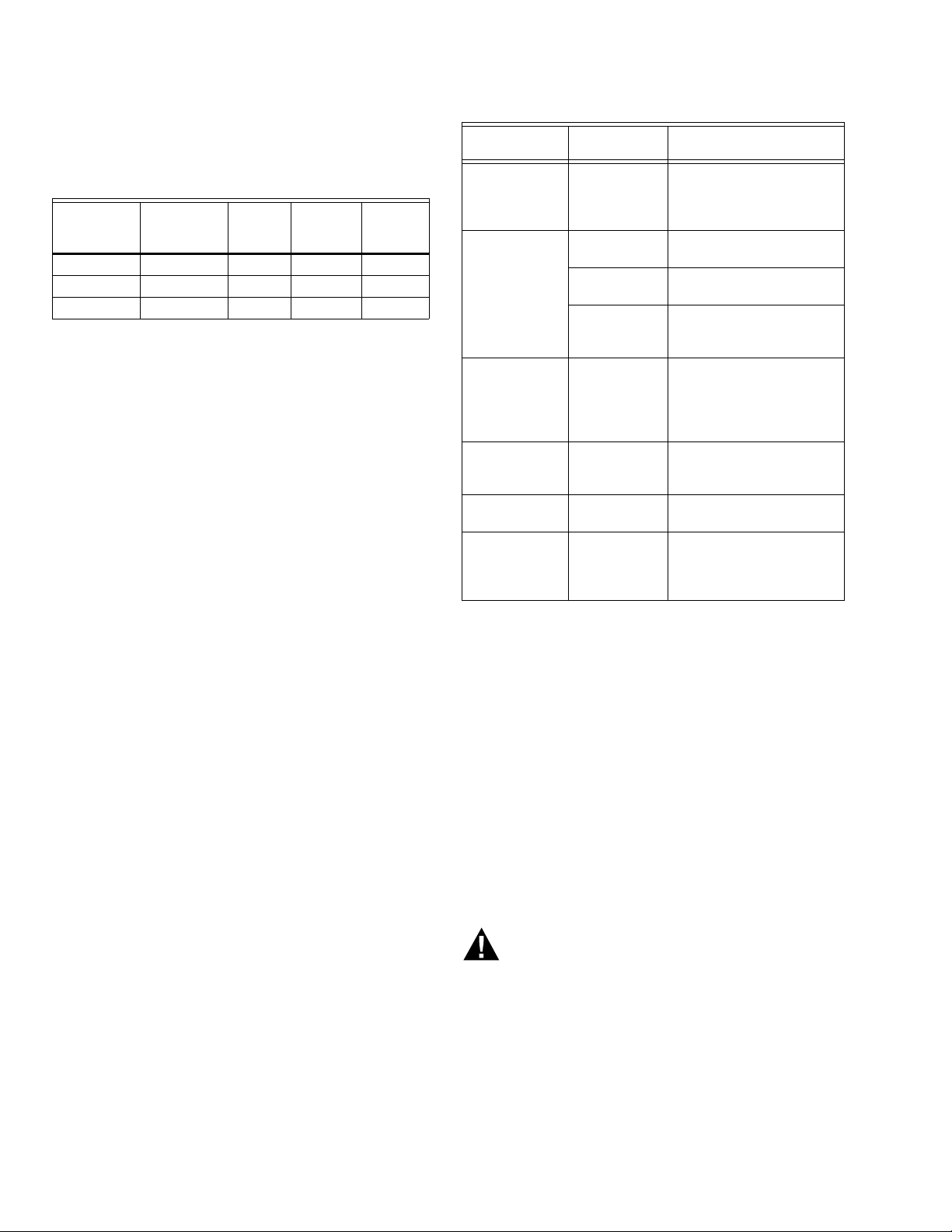
The Sylk IO devices are available in three models, as
described in Table 1.
Table 1. Device Configurations.
UI
(Universal
Devices
SI06042 6 0 4 2
SI04022 4 0 2 2
SI012000 12 0 0 0
Each device is programmable because the user chooses
which function blocks to use and how to connect them. It
is configurable because each function block has userdefined behavior.
Input)
DI
(Digital
Input)
AO
(Analog
Output)
DO
(Digital
Output)
SPECIFICATIONS
General Specifications
Electrical
Rated Voltage: 20-30 Vac; 50/60 Hz
Power Consumption:
100 VA for Sylk IO device and all connected loads
Sylk IO Device Only Load (Excluding Digital Triac Out-
puts): 3 VA maximum (SIO12000), 4 VA maximum
(SIO4022), 5 VA maximum (SIO6042)
Environmental
Operating & Storage Temperature Ambient Rating:
Minimum -40° F (-40° C); Maximum 150° F (65.5° C)
Relative Humidity: 5% to 95% non-condensing
Digital Triac Output (DO) Circuits
Voltage Rating: 20 to 30 Vac @ 50/60Hz
Current Rating: 25 mA to 500 mA continuous, and
800 mA (AC rms) for 60 milliseconds
Analog Output (AO) Circuits
Analog outputs can be individually configured for current
or voltage.
ANALOG CURRENT OUTPUTS:
Current Output Range: 4.0 to 20.0 mA
Output Load Resistance: 550 Ohms maximum
Table 2. Universal Input Circuit Specifications.
Input
Type
Room/Zone
Discharge Air
Outdoor Air
Tem per ature
Outdoor Air
Tem per ature
TR23
Setpoint
Potentiometer
Resistive Input Generic 100 Ohms
Voltage
Input
Discrete Input Dry Contact
a
C7031G and C7041F are recommended for use with
these controllers, due to improved resolution and accuracy when compared to the PT1000.
Sensor
Type
20K Ohm
NTC
C7031G
C7041F
PT1000
(IEC751
3850)
500 Ohm
to
10,500 Ohm
Tra nsduc er,
Controller
closure
a
a
Operating
Range
-40° F to 199° F
(-40° C to 93° C)
-40° to 120°F
(-40° to 49°C)
-40° to 250°F
(-40° to 121°C)
-40° F to 199° F
(-40° C to 93° C)
-4° DDC to 4° DDC
(-8° DDF to 7° DDF)
or
50° F to 90° F
(10° C to 32° C)
to
100K Ohms
0 - 10 Vdc
Open Circuit ≥
3000Ohms
Closed Circuit <
3000Ohms
BEFORE INSTALLATION
The device is available in three models (see Table 1).
Review the power, input, and output specifications on
page 2 before installing the device.
— Hardware driven by Triac outputs must have a
minimum current draw, when energized, of 25 mA and a
maximum current draw of 500 mA.
— Hardware driven by the analog current outputs must
have a maximum resistance of 550 Ohms, resulting in a
maximum voltage of 11 volts when driven at 20 mA. If
resistance exceeds 550 Ohms, voltages up to 18 Vdc
are possible at the analog output terminal.
ANALOG VOLTAGE OUTPUTS:
Voltage Output Range: 0 to 10.0 Vdc
Maximum Output Current: 10.0 mA
Analog outputs may be configured as digital outputs and
operate as follows:
– False (0%) produces 0 Vdc, (0 mA)
– True (100%) produces the maximum 11 Vdc, (22 mA)
Universal Input (UI) Circuits
See Table 2 for the UI circuit specifications.
31-00028—02 2
Electrical Shock Hazard.
Can cause severe injury, death or property
damage.
Disconnect power supply before beginning wiring
or making wiring connections to prevent electrical
shock or equipment damage.
INSTALLATION
The device must be mounted in a position that allows
clearance for wiring, servicing, and removal.
SYLK™ I/O DEVICES
M35144
NOTE: DEVICE CAN BE MOUNTED IN ANY ORIENTATION.
3/16 (4.5) PANEL MOUNTING HOLE (4X)
1 1 1 1 1 1 1 2 2 2 2 2
3 4 5 6 7 8 9 0 1 2 3 4
1 1
1 2 3 4 5 6 7 8 9 0 1 2
DEPTH IS
2-1/ 4 (57)
4-13/16 (122)
4-1/8 (105)
6-1/4
(159)
5-7/8
(149)
DIN RAIL
TOP TABS
BOTTOM FLEX
CONNECTORS
M16815
The device may be mounted in any orientation.
IMPORTANT
Avoid mounting in areas where acid fumes or other
deteriorating vapors can attack the metal parts of
the controller, or in areas where escaping gas or
other explosive vapors are present. See Fig. 1 for
mounting dimensions.
Mount Device
NOTE: The device may be wired before mounting to a
panel or DIN rail.
Terminal blocks are used to make all wiring connections to
the device. Attach all wiring to the appropriate terminal
blocks (see “Wiring” on page 5).
See Fig. 1 for panel mounting dimensions. See Fig. 2 on
page 3 for DIN rail mounting.
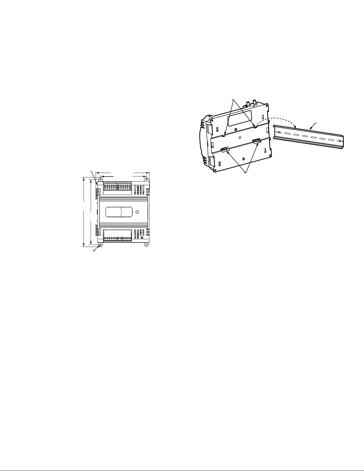
Fig. 1. Device dimensions in in (mm).
Panel Mounting
The device enclosure is constructed of a plastic base plate
and a plastic factory-snap-on cover.
NOTE: The device is designed so that the cover does not
The device mounts using four screws inserted through the
corners of the base plate. Fasten securely with four No. 6
or No. 8 machine or sheet metal screws.
The device can be mounted in any orientation. Ventilation
openings are designed into the cover to allow proper heat
dissipation, regardless of the mounting orientation.
DIN Rail Mounting
To mount the SIO12000, SIO4022, or SIO6042 device on a
DIN rail [standard EN50022; 1-3/8 in. x 9/32 in. (7.5 mm x
35 mm)], refer to Fig. 2 and perform the following steps:
need to be removed from the base plate for either
mounting or wiring.
1. Holding the device with its top tilted in towards the
DIN rail, hook the two top tabs on the back of the
device onto the top of the DIN rail.
2. Push down and in to snap the two bottom flex connectors of the device onto the DIN rail.
IMPORTANT
To remove the device from the DIN rail, perform
the following:
1. Push straight up from the bottom to release the
top tabs.
2. Rotate the top of the device out towards you and
pull the controller down and away from the DIN rail
to release the bottom flex connectors.
Fig. 2. Controller DIN rail mounting
(models SIO12000, SIO4022, and SIO6042).
Power
Before wiring the controller and device, determine the
input and output device requirements for each controller
and device used in the system. Select input and output
devices compatible with the controller, device, and the
application. Consider the operating range, wiring
requirements, and the environment conditions when
selecting input/output devices. When selecting actuators
for modulating applications consider using floating
control. In direct digital control applications, floating
actuators will generally provide control action equal to or
better than an analog input actuator for lower cost.
Determine the location of controllers, sensors, actuators
and other input/output devices and create wiring diagrams.
The application engineer must review the control job
requirements. This includes the sequences of operation
for the controller, and for the system as a whole. Usually,
there are variables that must be passed between
controllers that are required for optimum system-wide
operation. Typical examples are the TOD, Occ/Unocc
signal, the outdoor air temperature, the demand limit
control signal, and the smoke control mode signal.
It is important to understand these interrelationships
early in the job engineering process, to ensure proper
implementation when configuring the controllers.
Power Budget
A power budget must be calculated for each device to
determine the required transformer size for proper
operation. A power budget is simply the summing of the
maximum power draw ratings (in VA) of all the devices to
be controlled. This includes the controller itself and any
devices powered from the controller, such as equipment
actuators (ML6161 or other motors) and various
contactors and transducers.
3 31-00028—02

SYLK™ I/O DEVICES
IMPORTANT
• If a controller is used on Heating and Cooling
Equipment (UL 1995, U.S. only) and transformer
primary power is more than 150 volts, connect the
transformer secondary common to earth ground
(see Fig. 5 on page 6).
• When multiple controllers operate from a single
transformer, connect the same side of the transformer secondary to the same power input terminal in each device. The earth ground terminal
(terminal 3) must be connected to a verified earth
ground for each controller in the group (see Fig. 6
on page 7).
POWER BUDGET CALCULATION EXAMPLE
Table 3 is an example of a power budget calculation for
typical Spyder LON controller and Sylk IO devices. While
the example is shown for only these models, the process is
applicable for all controller and device configurations.
Table 3. Power budget calculation example.
VA
Informatio
Device
nObtained From
PUL6438SR 5.0 Spyder LON Product Data
Sheet
SIO6042
R8242A
Contactor fan
rating
5.0
21.0
a
See “Specifications” on
page 2.
TRADELINE
®
Catalog
inrush rating
D/X Stages 0.0 For example, assume
cooling stage outputs are
wired into a compressor
control circuit and have
no impact on the budget.
M6410A Steam
Heating Coil
Valve
0.7
TRADELINE® Catalog,
0.32A 24 Vac
TOTAL 31.7
a
Excludes the use of digital Triac outputs.
The system example above requires 31.7 VA of peak power.
Therefore, a 100 VA AT92A transformer could be used to
power one controller and device of this type. Because the
total peak power is less than 33 VA, this same transformer
could be used to power this configuration and meet NEC
Class 2 restrictions (no greater than 100 VA).
See Fig. 4–Fig. 6 beginning on page 6 for illustrations of
controller power wiring. See Table 4 for VA ratings of
various devices.
Table 4. VA ratings for transformer sizing.
Device Description VA
PVL0000AS,
PVL4022AS, and
Controller and Actuator
a
9.0
PVL6436AS
controllers and
Series 60 Floating
Damper Actuator
PUL1012S,
PUL4024S,
Controller
a
5.0
PUL6438S,
PVL4024NS, or
PVL6438NS
SIO12000
IO Device
a
3.0
SIO4022 4.0
SIO642 5.0
ML684 Versadrive Valve Actuator 12.0
ML6161 Damper Actuator, 35 lb-in. 2.2
ML6185
Damper Actuator SR 50 lb-in
12.0
ML6464 Damper Actuator, 66 lb-in. 3.0
ML6474 Damper Actuator, 132 lb-in. 3.0
R6410A Valve Actuator 0.7
R8242A Contactor 21.0
a
When used, each digital Triac output can add an addi-
tional 22 VA (peak) and 12 VA long-term.
For contactors and similar devices, the in-rush power ratings
should be used as the worst case values when performing
power budget calculations. Also, the application engineer
must consider the possible combinations of simultaneously
energized outputs and calculate the VA ratings accordingly.
The worst case, which uses the largest possible VA load,
should be determined when sizing the transformer.
Each device requires 24 Vac power from an energy-limited
Class II power source. To conform to Class II restrictions
(U.S. only), transformers must not be larger than 100 VA. A
single transformer can power more than one device.
GUIDELINES FOR POWER WIRING ARE AS FOLLOWS:
— For multiple devices operating from a single trans-
former, the same side of the transformer secondary
must be connected to the same power input terminal in each device. The earth ground terminal must
be connected to a verified earth ground for each
device in the group (see Fig. 6 on page 7). Device
configurations are not necessarily limited to three
devices, but the total power draw, including accessories, cannot exceed 100 VA when powered by the
same transformer (U.S. only).
— See Fig. 5 on page 6 for device power wiring used in
UL 1995 equipment (U.S. only).
— Many devices require all loads to be powered by the
same transformer that powers the device.
— Keep the earth ground connection wire run as short
as possible (refer to Fig. 4–Fig. 6 beginning on
page 6).
— Do not connect earth ground to the device’s digital
or analog ground terminals (refer to Fig. 4 and
Fig. 6).
— Unswitched 24 Vac power wiring can be run in the
same conduit as the L
ONWORKS® Bus cable.
31-00028—02 4
 Loading...