

Honeywell SHC Installation Instructions Manual
® U.S. Registered Trademark ▪ All Rights Reserved.
Copyright © 2010 Honeywell Inc. MU1B-0441GE51 R0710B
Type SHC
SUPERHEAT CONTROLLER – OEM VERSION
INSTALLATION INSTRUCTIONS
GENERAL
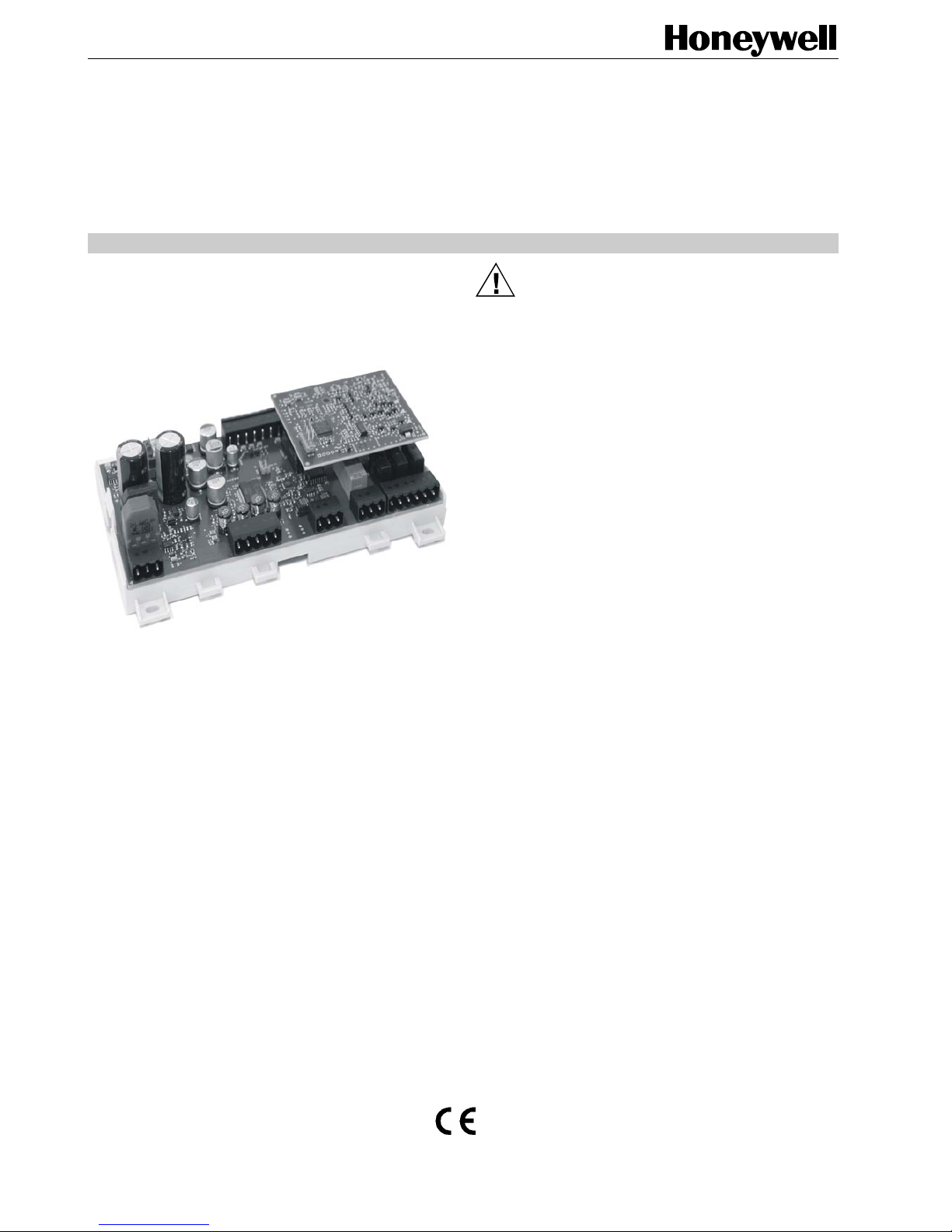
The OEM SHC Controller comes complete with base plate,
main board, plug-in board, and a set of terminal blocks.
Fig. 1. OEM SHC Controller
There are two configurations to choose from, depending
upon your desired application:
Configuration for Brine-to-Water Heat Pumps: Control
algorithm for liquid/liquid refrigeration circuit is preselected. Use of Honeywell temperature sensor type TSNFR and Honeywell pressure sensor type PSR is
required. Application-specific settings available, upon
request.
Configuration for Air-to-Water Heat Pumps: Control
algorithm for air/liquid refrigeration circuit is pre-selected.
Use of Honeywell temperature sensor type TS-NFR and
Honeywell pressure sensor type PSR is required.
Application-specific settings available, upon request.
BEFORE INSTALLATION
IMPORTANT
It is recommended that the SHC Controller be kept at
room temperature for at least 24 hours before applying power; this is to allow the evaporation of any
condensation resulting from low shipping / storage
temperatures.
CAUTION
• T he product may be mounted only by trained pers onnel who are
thoroughly familiar with all pertinent electrical safet y rules.
• T o avoid el ectrical shock or equipment damage, you must turn
OFF the power supply before attaching / rem ovi ng connections
to/from any terminals.
• Do not power the SHC with line voltage!
• If the product is mount ed where unauthori zed pers onnel has
access, the relays may not be used for switching li ne voltage
(230 Vac).
• In case of relays switching line vol t age, two neighboring relays
may switch the same phase, only.
• Sensors and secondary (output) of transformer may not be
grounded simultaneously.
• Groundi ng of secondary (output) of transformer is not
recommended.
• Alarm relay without power must be recognized as “al arm” if used.
• A 24 V emergency battery module (not i ncluded) can be
connected to the SHC to enable safe closing in the event of a
power failure. 1 Ah is recommended.
• Sensors with current output 4...20 mA and ratiometric voltage
output 0.5 V…4.5 V may not be used simultaneously.
• Connecting sensors by wires more t han 6 m long may decrease
the accuracy of measured values .
• T o prevent damage to the compressor, the signal indicating
whether the compressor is runni ng or not must be connected to
the SHC’s enabler input in c ase the SHC is in the Automatic
Superheat Control mode while COLD STORE supervision is
disabled. If the SHC is operating in the Automatic Superheat
Control mode and COLD STORE supervision i s simultaneously
enabled, the enabler input can be used (e. g. , for main power
indication), but it may not be connected with compres s or . If the
SHC is operating in any mode other than the Automatic
Superheat Control mode, the enabler i nput i s ignored.
• If supply voltage has been accidental l y appli ed to the
voltage/current input, wait at leas t 15 minutes before switching
the SHC ON.
• Disabling the Low superheat alarm and High superheat alarm is
not recommended.
• Possible LOP alarm will be erased aut omatically when the SHC
enters the MANUAL, REMOTE, or CONFIGURATION mode.
• A switch or circuit-breaker must be incl uded i n the installation; it
must be installed in close proximity to the controll er and must be
marked as the disconnec ting device for the controller.
• If one of the supported Honeywell transformers (see section
“Accessories”) is not used to supply the SHC controller, protect
the power input line G using an external 3A type T fuse.
OEM SHC CONTROLLER – INSTALLATION INSTRUCTIONS
MU1B-0441GE51 R0710B 2
Approvals, Certifications, and Standards
Approvals and Certifications
• CE-approved according to IEC60730
• No hazardous substances according RoHS 2002/95/EC
• Waste disposal according Waste Electrical and Electronic
Equipment Guideline WEEE 2002/96/EEC
Classification according to EN60730-1
Environmental conditions: For use in home (residential,
commercial, and light-industrial)
and industrial environments
Pollution degree: 2
Insulation class: 3
Protection against vibration: 5g as per IEC 60068-2-6
(10 … 500 Hz) (applicable for
wall mounting, only)
Protection against shock: 50g as per IEC 60068-2-27
(applicable for wall mounting,
only)
Classification according to EN60529
(Degree of Protection Provided by Enclosures)
IP00
Ambient Environmental Limits
Operating temperature: -25 … +60 °C at 5…90% r.H.
Storage temperature: -25 … +70 °C at 5…90% r.H.
Temperature Control Accuracy
Superheat temperature: < 1.0 K
Minimum stable signal: < 2.0 K
Weight
Without screw terminals: 220 g
With screw terminals: 290 g
INSTALLATION
Mounting
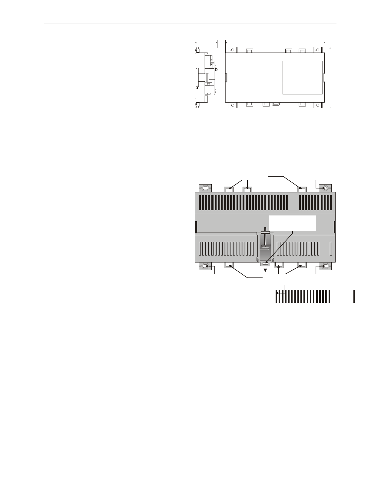
The OEM SHC Controller has the dimensions:
181 x 110 x 40 mm (W x L x H).
The OEM SHC Controller is suitable for mounting on both a
standard rail (DIN EN 50022-35 x 7,5) and for installation in
wiring cabinets, in fuse boxes, and on walls/ceilings. The
controller can operate in both horizontal and vertical position.
18140
110
Fig. 2. OEM SHC Controller, dimensions (mm)
DIN Rail Mounting/Dismounting
The unit can be mounted onto a DIN rail simply by snapping
it into place and securing it with a stopper to prevent sliding.
It is dismounted by gently pulling the stirrup located in the
base of the housing (see Fig. 3).
SCREWING NOSE
(oval hole)
SCREWING NOSE
(oval hole)
SCREWING NOSE
(oval hole)
EYELETS FOR
CABLE BINDERS
EYELETS FOR
CABLE BINDERS
SCREWING NOSE
(round hole)
STIRRUP; PULL DOWN
TO DISMOUNT UNIT
FROM RAIL
Fig. 3. Housing base (view from below)
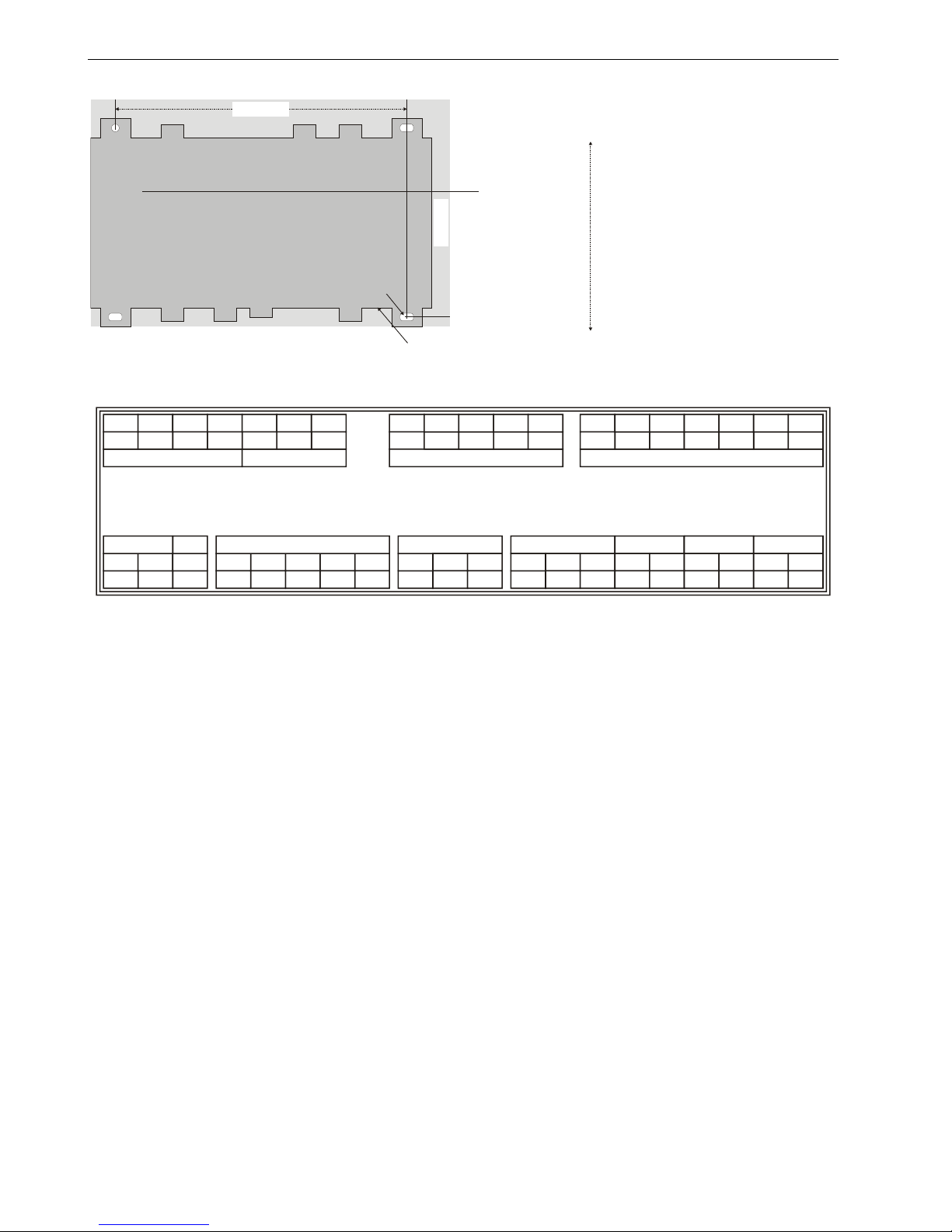
Wall/Ceiling Mounting/Dismounting
The unit can be mounted on walls or ceilings in any
orientation desired. In the case of ceiling mounting, however,
it should not be operated at ambient temperatures exceeding
45 °C. The unit is mounted by inserting 3.5-mm dowel screws
through the corresponding screwing noses (see Fig. 4).
OEM SHC CONTROLLER – INSTALLATION INSTRUCTIONS
MU1B-0441GE51 R0710B 3
154 mm
100 mm
oval hole
(4x7 mm)
round hole
(diameter: 4 mm)
Fig. 4. Drilling template (view from above)
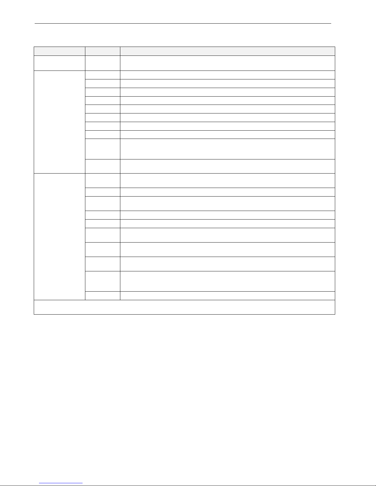
Terminal Assignment
The terminal blocks are arranged on two sides of the controller: the sensor side and the relay side. The terminals on
the controller consist of multiple sockets for screw terminal
plugs which come together with the controller.
The sensor side (terminals 21-39) consists of terminals
for six analog inputs, one analog output, and three digital
inputs.
The relay side (terminals 1-20) consists of terminals for
power supply (24 Vac/dc), the output for the bipolar
stepper motor, the RS485 interface, and the four relays.
NOTE: According to VDE guidelines, it is not allowed to mix
low-voltage and high-voltage signals on the relays.
32
9
A
OUT1AOUT1B
OUT2AOUT2BEARTH
87
6
5
4
3
21
G G0 BAT
24 Vbat
RS485 (isolated)
relay 4 (SPDT) relay 1 (NO)
relay 2 (NO)relay 2 (NO)relay 3 (NO)
bipolar stepper motor
24 Vac/dc
B
GNDX
10
11 12
C4 NO4 NC4 C1 NO1 C2 NO2 C3 NO3
13
14
15 16
17
18 19 20
39 38 37 36 35 34 33
inputs: 4...20 mA / ratiometric / 0...10 V
digital inputs
0...10 V output
inputs: Pt1000, NTC10k, NTC20k / ratiometric / 0...10 V
R1 GNDAOGNDGNDGND
D3
D2D1
GND GND GND
V5/15 V5/15
R2
U2 U1
T2 T1
31 30 29 28
27
26 25
24
23
22 21
Fig. 5. Terminal layout and location on controller

OEM SHC CONTROLLER – INSTALLATION INSTRUCTIONS
MU1B-0441GE51 R0710B 4
Table 1. Terminal assignment
term. #
name
description
1
G
voltage supply 24 Vac/dc (+)
2
G0
voltage supply 24 Vac/dc (-)
3
BAT
buffer battery module 24 V (+) with power level indicator
4 EARTH
earth / shielding
5
OUT2B
output 2B of stepped motor
6
OUT2A
output 2A of stepped motor
7
OUT1B
output 1B of stepped motor
8
OUT1A
output 1A of stepped motor
9 A
RS485, A + conductor
10
B
RS485, B - conductor
11
GNDX
RS485, isolated ground
12
C4
relay 4, change-over contact
13
NO4
relay 4, normally-open contact NOC
14
NC4
relay 4, normally-closed contact NCC
15
C1
relay 1, change-over contact
16
NO1
relay 1, normally-open contact NOC
17
C2
relay 2, change-over contact
18
NO2
relay 2, normally-open contact NOC
19
C3
relay 3, change-over contact
20
NO3
relay 3, normally-open contact NOC
21
T1
AIN1: temperature input 1 (NTC10K, NTC20K, Pt1000)
22
GND
AIN1/2: ground for temperature inputs 1 + 2
23
T2
AIN2: temperature input 2 (NTC10K, NTC20K, Pt1000)
24
U1
AIN3: universal input 1 (NTC10K, NTC20K, Pt1000, 0,5…4,5 V ratiometric, 0…10 V)
25
GND
AIN3/4: ground for universal inputs 1 + 2
26
V5/15
AIN3/4: sens or voltage supply for universal inputs 1 + 2
27
U2
AIN3: universal input 2 (NTC10K, NTC20K, Pt1000, 0,5…4,5 V ratiometric, 0…10 V)
28
R2
AIN6: current/voltage input 2 (0.5…4.5 V, 0…10 V, 4…20 mA)
29
GND
AIN6: ground for current/voltage input 2
30
V5/15
AIN5/6: sens or voltage supply for current/voltage inputs 1 + 2
31
GND
AIN5: ground for current/voltage input 1
32
R1
AIN5: current/voltage input 1 (0.5…4.5 V, 0…10 V, 4…20 mA)
33
AO
AO1: analog output 1 (0…10V)
34
GND
AO1: ground for analog output 1
35
GND
DI1/2/3: ground for digital inputs 1 + 2 + 3
36
D3
DI3: digital input 3 (log.1 = contact open or 24 Vac/dc, log.0 = short-circuit or < 2 Vac/dc)
37
D2
DI2: digital input 2 (log.1 = contact open or 24 Vac/dc, log.0 = short-circuit or < 2 Vac/dc)
38
D1
DI1: digital input 1 (log.1 = contact open or 24 Vac/dc, log.0 = short-circuit or < 2 Vac/dc)
39
GND
DI1/2/3: ground for digital inputs 1 + 2 + 3
LEDs
The OEM SHC Controller features three LEDs: a green power LED (LED 1), a red alarm LED (LED 2), and a yellow status LED
(LED 3). The various different possible blinking patterns and the corresponding meanings are listed in Table 2.
After power-up, all of the LEDs are illuminated for a short time during a factory self-test.
OEM SHC CONTROLLER – INSTALLATION INSTRUCTIONS
MU1B-0441GE51 R0710B 5
Table 2. LED blinking patterns and corresponding meanings
LED behavior meaning
LED 1
(green power LED)
ON Power is ON.
LED 2
(red alarm LED)
always ON -always OFF No alarm
single blink Power failure (the SHC will then run on battery)
2 blinks Low superheat alarm is active
3 blinks High superheat alarm is active
4 blinks Sensor failure due to sensor break or sensor short-circuit
5 blinks LOP protection is active
6 blinks Configuration error
7 blinks
Communication failure. Communication with appliance controller is missing. Periodic
messages are not being received. Bus cable broken or appliance controller has been
switched OFF.
8 blinks
Hardware self-test alarm. One of the following voltages is outside the permitted range:
motor voltage, relay supply voltage, sensor supply voltage, AO voltage
LED 3
(yellow status LED)
always ON
SHC is disabled or (due to any error or alarm condition) control is absent (which
automatically disables the SHC)
always OFF SHC is running without EEV movement
single blink
The EEV is opening, closing, or synchronizing. A single blink (until the OFF position is
achieved; EEV in safety position; REV to close) also indicates that the SHC is powering up.
2 blinks REV valve is moving (i.e., the REV delay time is currently elapsing)
3 blinks Start ramp (incl. holding time) is active
4 blinks
“Pump down” is active or the compressor is waiting to switch ON, but the compressor min.
OFF time is active.
5 blinks
MOP protection is active. This LED behavior has a higher priority than “start-up ramp is
active” (see above)
6 blinks
HITCond protection is active. This LED behavior has a higher priority than “start-up ramp is
active” (see above)
7 blinks
Waiting for ALL Enabled conditions. If there is more than just one “SHC Enabled” condition,
the SHC will wait until all “SHC Enabled” conditions are TRUE. The conditions can come
from hardware (DI), network, or Cold store logic.
8 blinks EEV is in the manual override mode; no superheat control from PI control active.
*Each blink has a duration of 300 msec, with intervals of 300 msec between multiple blinks. The blinking pattern is then repeated
every few seconds.
POWER SUPPLY
General Information
NOTE: Local wiring guidelines (e.g. VDE 0100) may take
precedence over recommendations provided in
these installation instructions.
NOTE: To comply with CE requirements, devices having a
voltage of 50...1000 Vac or 75...1500 Vdc but lacking
a supply cord, plug, or other means for
disconnecting from the power supply must have the
means of disconnection incorporated in the fixed
wiring. This means of disconnection must have a
contact separation of at least 3 mm at all poles.
All wiring must comply with applicable electrical codes and
ordinances. Refer to job or manufacturers’ drawings for
details. Use a min. of 18 AWG (1.0 mm
2
) and a max. of
14 AWG (2.5 mm
2
) for all power wiring.
Connecting to the Power Supply
The power supply (24 Vac [±20%], 50/60 Hz or 24 Vdc
[±10%]) is connected to terminals 1 and 2.
NOTE: Do not reverse the polarity of the power connection
cables and avoid ground loops (i.e. avoid connecting
one field device to several controllers as this may
result in short circuits damaging your device.
The maximum power consumption will not be higher than 50
VA at 24 Vac ±20%.
OEM SHC CONTROLLER – INSTALLATION INSTRUCTIONS
MU1B-0441GE51 R0710B 6
Buffer Battery
A 24 V emergency battery module with internal charge
control can be connected to the controller terminal 3 to
enable safe closing at power failure. 1 Ah is recommended.
The battery module provides power voltage only in the event
of a power supply failure (at terminals G and G0). If the
microprocessor detects that power is being fed in simultaneously via terminals G and G0 and from the battery
module, this is recognized as a power supply failure.
INPUTS/OUTPUTS
General Information
The controller is equipped with removable screw-type
terminal blocks which allow the terminal assignment to be
made before plugging them into the unit and to be preserved
after unplugging them from a unit requiring repair or
replacement.
Wiring the Inputs/Outputs
The screw-type terminals support wiring with flexible or
massive cables of 0.35 mm² up to 2.5 mm².
Two wires with a total thickness of 14 AWG can be twisted
together and connected using a wire nut (include a pigtail
with this wire group and attach the pigtail to the individual
terminal block). Deviations from this rule can result in
improper electrical contact. Local wiring codes may take
precedence over this recommendation. Wire to the terminal
blocks as follows:
1. Strip 5/16 in. (8 mm) insulation from the conductor.
2. Insert it at the required terminal location, and tighten the
screw to complete the termination. Fix the cable using
cable binders if required.
HARDWARE FEATURES
Stepper Motor Output
The controller is able to drive bipolar stepper motors with
12 V or with 24 V supply voltage. The stepper motor is
connected to terminals 4 to 8 (see terminal assignment) with
shielded motor cable.
Stepper Motor Parameters
Motor voltage 12 V or 24 V, current (chopper)
control
Step frequency 10…62,5 steps/sec
Motor current 80…800 mA
Holding current 0…100% of the motor current, in
approx. 10% steps
Max. no. of steps 1…10,000 steps
No. of opening steps 1…1,000 steps
Besides the Honeywell electronic expansion valve type EEV
(models EV2, EV3, EV4), the controller provides presettings
for the stepper motor valves listed in Table 3 with the corresponding parameters. These valves can be configured by
just choosing the valve type. Other valves which fit to the
above listed ranges of stepper motor parameters can be
configured manually.
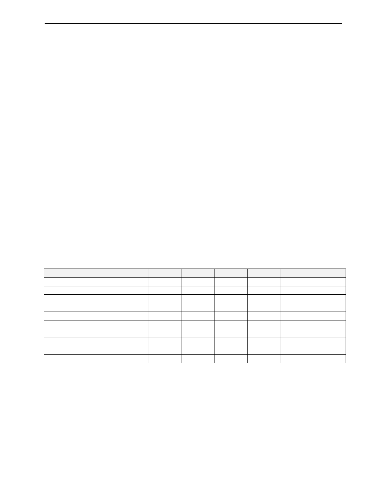
Table 3. Supported valves (presettings)
model min. step max. step step close steps / sec peak [mA] hold [mA] duty [%]
Carel E2V, E3V, E4V 50 480 520 50 450 100 30
RS485
The controller provides an isolated RS485 communication
interface which is connected to terminals 9 to 11 (see Table
1).
The max. permissible number of devices simultaneously
connected to RS485 output is 32. The RS485 cable is of
impedance 120 Ohm with maximum length of 1000 m.
Connection via STP (Shielded twist pair) is recommended.
Terminal resistors 120 Ohm for terminal devices are
recommended for length > 40 m. The communication
frequency (baudrate) can be one of the following: 2400,
4800, 9600, 19200, 28800, 38400, 57600, or 115200.
 Loading...