

Page 1
Heating Controller SDC
Remote Heating Controller DHC
OPERATING INSTRUCTIONS
EN2H-0220GE51 R0308
Page 2

EN2H-0220GE51 R0308
Page 3

SDC / DHC Contents
Contents
1 Software version ............................................................................................................. 7
2 Safety instructions.......................................................................................................... 7
2.1 Intended use ........................................................................................................ 7
2.2 Requirements for start-up .................................................................................... 7
2.2.1 Power supply........................................................................................... 8
2.2.2 Connection conditions............................................................................. 8
2.2.3 Cable cross-sections............................................................................... 8
2.2.4 Maximum cable lengths .......................................................................... 8
2.2.5 Cable installation..................................................................................... 8
2.2.6 Grounding and zeroing............................................................................ 9
2.3 Hot-water temperature greater than 60 °C .......................................................... 9
2.4 Connection of accessory parts .......................................................................... 10
2.5 Maintenance and cleaning................................................................................. 10
3 Overview ........................................................................................................................11
4 Operation .......................................................................................................................12
4.1 Display and operating elements ........................................................................ 12
4.1.1 Display (basic display) .......................................................................... 13
4.1.2 Operating elements............................................................................... 14
4.1.2.1 Input button (press / turn) ........................................................ 14
4.1.2.2 "Daytime room temperature" button ........................................ 14
4.1.2.3 "Night-time room temperature" button..................................... 15
4.1.2.4 "Daytime hot-water temperature" button ................................. 15
4.1.2.5
4.1.2.6 "Switching time programs / Holiday programs" button............ 23
4.1.2.7 "System information" button .................................................... 26
4.1.2.8 "Manual mode" / "Emission measurement" button ................. 28
4.1.2.9 Heating curve .......................................................................... 30
4.2 Menu-selection level .......................................................................................... 31
EN2H-0220GE51 R0308 3
"Operating mode" button (basic display)................................. 16
Page 4

Contents SDC / DHC
4.2.1 "Time - Date" menu............................................................................... 33
4.2.2 "Timeprograms" menu .......................................................................... 34
4.2.2.1 Selection of the control circuit ................................................. 35
4.2.2.2 Selection of the program ......................................................... 35
4.2.2.3 Selection of day of the week and cycle ................................... 35
4.2.2.4 Programming switching times and cycle temperatures........... 36
Block programming...............................................................................................................44
4.2.3 "System Parameters" menu .................................................................. 51
4.2.3.1 Language selection ................................................................. 51
4.2.3.2 Time program .......................................................................... 52
4.2.3.3 Operating mode....................................................................... 52
4.2.3.4 Summer / Heating limit ............................................................ 54
4.2.3.5 Parameter reset....................................................................... 55
4.2.4 "DHW" menu ......................................................................................... 56
4.2.4.1 Night-time hot-water temperature ........................................... 56
4.2.4.2 Legionella protection day ........................................................ 56
4.2.5 "Direct Heating Circuit" / "Mixed Heating Circuit 1" / "Mixed
Heating Circuit 2" menu ........................................................................ 57
4.2.5.1 Reduced operation .................................................................. 57
4.2.5.2 Heating system........................................................................ 58
4.3 Error messages.................................................................................................. 59
5 Log.................................................................................................................................. 60
4 EN2H-0220GE51 R0308
Page 5

SDC / DHC Contents
EN2H-0220GE51 R0308 5
Page 6

Page 7

SDC / DHC Software version
Pos: 1 /156-Honeywell/Softwareversion/Softwareversion @ 0\mod_1207134342657_6.doc @ 9090
1 Software version
This documentation is valid for software version V 3.0 of your
control device. The software version is displayed after switch-on
for approx. 8 s. If you are using an older software version, please
contact your heating technician.
Pos: 2 /156-Honeywell/Siche rheitshinw eise /Sicherhe itshinw eise @ 0 \mod_1207 1344144 54_6.do c @ 9105
2 Safety instructions
2.1 Intended use
The SDC / DHC Smile family of controllers was designed for the
sole purpose of regulating and controlling hot-water, heating and
district heating systems (including hot-water production) that do
not exceed a maximum flow temperature of 120 °C.
2.2 Requirements for start-up
ATTENTION
The heating system must be complete and filled with water
so that the pumps do not run dry and the heating boiler is not
damaged.
The control equipment must be installed in accordance with
the installation instructions.
All electrical connections (voltage supply, burner, mixer
motor, pumps, sensor wiring etc.) must be carried out by the
technician in accordance with the applicable VDE regulations
and correspond with the circuit diagrams.
If floor heating is connected, a limiting thermostat must also
be installed in the flow line after the heating circuit pump.
This switches off the pumps at excessive flow temperatures.
Before starting up the controller, have the heating technician
check all requirements listed above.
NOTE
The current time and date are already set at the factory and are
backed up by a battery.
The time switch functions based on a basic program and the
control functions are preset for common heating systems with lowtemperature boilers.
EN2H-0220GE51 R0308 7
Page 8

Safety instructions SDC / DHC
2.2.1 Power supply
Do not disconnect the controller from the mains supply!
The battery for saving all individualised data is otherwise
unnecessarily strained. The frost-protection function of the
controller is deactivated.
2.2.2 Connection conditions
All electrical connection work may only be carried out by qualified
personnel!
2.2.3 Cable cross-sections
2
1.5 mm
for all cables carrying 230 V (power supply, burner,
pumps, actuator).
2
0.6 mm
0.5 mm
for bus cables (recommended type J-Y(St)Y 2 x 0.6)
2
for sensors, selectors and analog signal cables.
2.2.4 Maximum cable lengths
Sensor, selector and analog inputs
We recommend using cables no longer than 200 m. Longer
connection lines could be used, but increase the risk of
interference.
Relay outputs
Unlimited cable length.
Bus connections
Max. length of 100 m from the first bus subscriber to the last one
(incl. wall modules).
2.2.5 Cable installation
Install cables for sensors apart from the cables carrying 230 V!
Branch boxes in the sensor cable must be avoided!
8 EN2H-0220GE51 R0308
Page 9

SDC / DHC Safety instructions
/
2.2.6 Grounding and zeroing
Local regulations on the connection of equipment must be
observed!
2.3 Hot-water temperature greater than 60 °C
ATTENTION
Note that there is a danger of scalding at all hot-water drawoff points (kitchen, bathroom etc.) in the following cases.
Add sufficient cold water in these cases.
Automatic anti-
legionella mechanism
When the automatic anti-legionella mechanism is activated, the
hot water is automatically heated to the anti-legionella
temperature (65 °C at the factory) on the selected day and at the
selected time to kill any legionella bacteria found in the hot-water
tank.
Manual mode
Emission
measurement
In the manual mode / emission measurement operating mode, the
hot water is heated up to the highest possible boiler temperature,
as the burner and all pumps are switched on and the mixer is
opened fully. There is an acute danger of scalding at all
connected hot-water draw-off points! Add sufficient cold water or
switch off the hot-water loading pump (at the switch of the pump,
if present). Heating and hot water are in unregulated continuous
operation. This operating mode is for special use by the chimney
sweep for emission measurement or if the controller is defective.
The high hot-water temperatures can be prevented, however, by
setting the boiler thermostat to a max. boiler temperature of
approx. 60 °C.
EN2H-0220GE51 R0308 9
Page 10

Safety instructions SDC / DHC
2.4 Connection of accessory parts
WARNING
According to VDE 0730, a separator for each mains terminal
is to be provided in the voltage supply to the control
equipment. Observe the local regulations regarding
grounding and zeroing.
As soon as the mains voltage is applied to terminals 21, 22,
2, 6, 12 and 18, headers X3 and X4 can also carry mains
voltage.
If the heating circuit and hot-water loading pumps do not
have an On / Off switch, but manual switch-on and switch-off
capability is still desired, the appropriate switches must be
installed by the customer. All accessory parts (sensors,
selectors etc.) are to be connected to the respective circuit
diagram.
2.5 Maintenance and cleaning
The controller is maintenance-free. The device can be cleaned
externally with a moist (not wet) cloth.
Pos: 3 /156-Honeywell/Bedienu ng/Ueber sicht @ 1 \mod_1 20764345 9088_6.do c @ 9180
10 EN2H-0220GE51 R0308
Page 11
SDC / DHC Overview
3 Overview
The modular SDC / DHC control device is available in an
installable switch cabinet version and a surface-mounted wall
version with the following equipment features:
Type
SDC 3-10
SDC 3-40
SDC 7-21 1)
SDC 9-21 2)
SDC 12-31 3)
Number of output relays
Burner stage 2
or
District heating valve
CLOSED
Burner stage 1
Direct heating circuit
Variable output 3
Mixed heating circuit 1
Mixed heating circuit 2
Tank loading pump
Variable output 2
3 – x x – – x –
3 – – – x – – – –
7 – x x x – x – –
7
x x x x – x x x
+ two
variable
relays
10
x x x x x x x x
+ two
variable
relays
1)
DHC 43-1
2)
DHC 43-2
3)
DHC 43-3
Pos: 4 /156-Honeywell/Bedienu ng/Anzei gen_un d_Bedien elemen te @ 1\mod _1207643 591494_ 6.doc @ 9 195
Variable output 1
EN2H-0220GE51 R0308 11
Page 12
Operation SDC / DHC
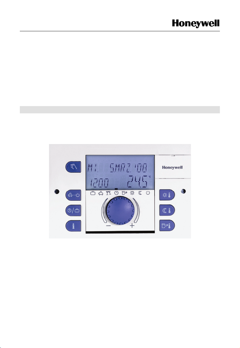
4 Operation
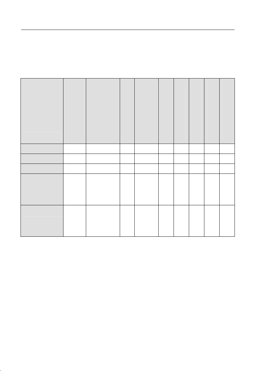
4.1 Display and operating elements
5
1
2
3
4
1011
6
7
8
9
1 "Manual mode" / "Emission measurement" button (not on
district heating controllers)
2 "Operating modes" button (basic display)
3 "Switching time programs" / "Holiday programs" button
4 "System information" button
5 Display
6 Cover clip for service socket
7 "Daytime room temperature" button
8 "Night-time room temperature" button
9 "Daytime hot-water temperature" button
10 Input button (press / turn)
11 Operating mode symbols (heating programs)
Pos: 5 /156-Honeywell/Bedienu ng/Disp lay_Gru ndanzeige @ 1\mo d_12076 43647963 _6.doc @ 9 210
12 EN2H-0220GE51 R0308
Page 13
SDC / DHC Operation
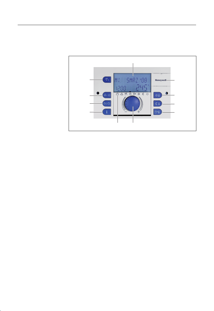
4.1.1 Display (basic display)
1
C
2
5
3
4
1 Day of the week / Date 4 Operating mode symbols
2 Time 5 Heat generator temperature
3 Active operating mode
The illumination of the display is switched on by pressing any
button or using the input button
î and switches off automatically
if no buttons are pressed for a longer period of time.
During start-up of the unit and after a power failure, a segment
test with automatic fault diagnosis is carried out. The respective
device type and the software version number then appear briefly.
The basic display that then appears shows the day of the week,
the date, the time and the heat generator temperature in
automatic mode. Different values appear in the basic display
depending on the set operating mode (AUTOMATIC, PARTY
etc.). Thus, for example, in the ABSENT operating mode, the
indication ABSENT TIL appears instead of the date and the return
date instead of the temperature. Active summer deactivation is
indicated by a beach umbrella symbol
protection is indicated by a snowflake symbol
À, and active frost
Á.
Pos: 6 /156-Honeywell/Bedienu ng/Bedie nelem ente @ 1\m od_1207 6437357 44_6.doc @ 9225
EN2H-0220GE51 R0308 13
Page 14

Operation SDC / DHC
4.1.2 Operating elements
Pos: 7 /156-Honeywell/Bedienu ng/Einga beknop f @ 1\mod _120764 3768135 _6.doc @ 9240
4.1.2.1 Input button (press / turn)
By pressing once, you can:
ð
• Confirm input / values
By pressing and holding (approx. 3 s), you can:
• Switch to the menu-selection level
• Move up one menu level
By turning the input button î, you can:
• Change values (clockwise increases called-up values,
anticlockwise decreases them)
• Navigate through menus
Pos: 8 /156-Honeywell/Bedienung/Taste_Tages-Raumtemperatur @ 1\mod_1207643818525_6.doc @ 9255
4.1.2.2 "Daytime room temperature" button
Sets the desired room temperature (room setpoint) in automatic
¥
mode during the heating cycles and in the PARTY and HEATING
operating modes. In operating mode 1, the set value for all
heating circuits is the same. In operating mode 2, the set value
applies for the respective heating circuit. To set the operating
mode, see 4.2.3.3 Operating mode, pg. 52.
Setting
► Press ¥ button.
► Set flashing room temperature specification to the desired
value by turning the input button
C
► Confirm set value by pressing the
î.
button
î.
¥ button or the input
Alternative: Automatic acceptance of the value after the set
information time (see 4.1.2.7 "System information" button, pg. 26).
Factory setting
Setting range
20 °C
5 ... 30 °C
Pos: 9 /156-Honeywell/Bedienu ng/Tas te_Nacht- Raumtem peratur @ 1\mod_ 12076439 18822_6 .doc @ 9270
14 EN2H-0220GE51 R0308
Page 15
SDC / DHC Operation
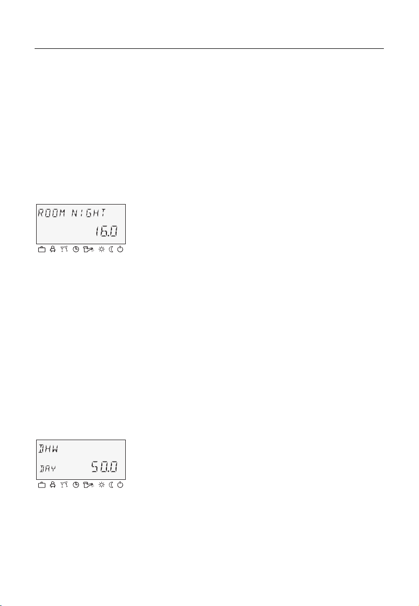
4.1.2.3 "Night-time room temperature" button
Sets the lowered room temperature in automatic mode between
¦
the heating cycles and in the ABSENT and RED. HEATING
operating modes.
In operating mode 1, the set value for all heating circuits is the
same. In operating mode 2, the set value applies for the
respective heating circuit. To set the operating mode, see
4.2.3.3 Operating mode, pg. 52.
Setting
► Press ¦ button.
► Set flashing room temperature specification to the desired
value by turning the input button
C
► Confirm set value by pressing the
button
î.
î.
¦ button or the input
Alternative: Automatic acceptance of the value after the set
information time (see 4.1.2.7 "System information" button, pg. 26).
Factory setting
Setting range
16 °C
5 ... 30 °C
Pos: 10 /156-Honeywell/ Bedien ung/ Tas te_Warm wasse rtem perat ur @ 1 \mod_ 120764 396371 3_6 .doc @ 92 85
4.1.2.4 "Daytime hot-water temperature" button
Sets the daytime hot-water temperature during the hot-water
§
operational-readiness times in automatic mode and in the PARTY
and HEATING operating modes. This set value also applies for
exclusively hot-water operation (manual summer operation).
Setting
► Press § button.
► Set flashing hot-water temperature to the desired value by
turning the input button
C
► Confirm set value by pressing the
î.
button
î.
§ button or the input
Alternative: Automatic acceptance of the value after the set
information time (see 4.1.2.7 "System information" button, pg. 26).
Factory setting
50 °C
EN2H-0220GE51 R0308 15
Page 16

Operation SDC / DHC
r
Setting range
One-time hot-wate
circuit loading
4.1.2.5 "Operating mode" button (basic display)
5 °C (hot-water economy temperature) ... Maximum hot-water
heater temperature limit (service setting)
Pressing and holding (approx. 3 s) the § button brings you to
the reload function, where the reload time can be set in minutes.
With a reload time of 0 minutes, loading is started once and the
hot-water tank is loaded to the daytime setpoint. The time for this
superimposed hot-water circuit loading can be set between 0 and
240 minutes. The current week program is superimposed here.
Pos: 11 /156-Honeywell/Bedienung/Taste_Betriebsart @ 1\mod_1207644003760_6.doc @ 9300
Sets the operating mode and returns to the basic display from
every operating level.
16 EN2H-0220GE51 R0308
Page 17
SDC / DHC Operation
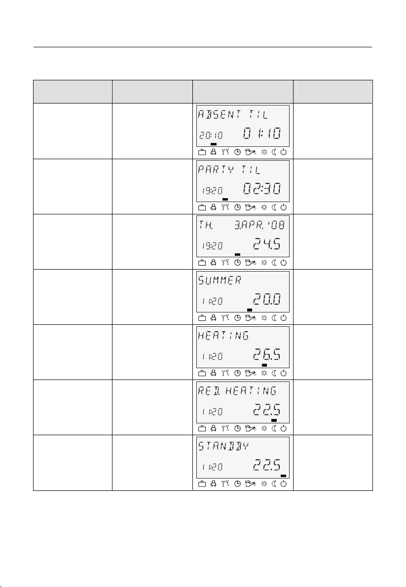
Overview of the operating modes
Symbol Operating mode Display Setting
ABSENT P1 (P2, P3)*, return
ç
PARTY P1 (P2, P3)*,
è
date
party end time
é
ê
ë
ì
í
AUTOMATIC
SUMMER
HEATING
RED. HEATING
STANDBY
* P2 and P3 only after enabling, see "System Parameters"
menu, parameter 2 = P1 to P3
P1 (P2, P3)*
C
P1(P2, P3)*
C
C
C
C
EN2H-0220GE51 R0308 17
Page 18

Operation SDC / DHC
The selected operating mode appears in plain text, whereby a
marking at the bottom edge of the display points to the respective
operating mode symbol at the same time. In operating mode 1,
the set value for all heating circuits is the same. In operating
mode 2, the set value applies for the respective heating circuit. To
set the operating mode, see 4.2.3.3 Operating mode, pg. 52.
Setting
► Press button.
Return to the basic
display
NOTE
4.1.2.5.1 Absence mode (short-term program)
Setting
Application
► Select operating mode by turning the input button
î. The
marking is located above the corresponding operating mode
symbol.
► Confirm set operating mode by pressing the
input button
î.
button or the
► With short-term operating modes (ABSENT, PARTY), set the
desired value by turning the input button
the
button or the input button î.
î and confirm with
Alternative: Automatic acceptance of the value after the set
information time (see 4.1.2.7 "System information" button, pg. 26).
Press the button for approx. 3 s to return to the basic display
from any operating level.
Holiday mode is set via the "Switching time programs / Holiday
programs" button (see 4.1.2.6 "Switching time programs / Holiday
programs" button, pg. 23).
Pos: 12 /156-Honeywell/ Bedien ung/ Abwes enhe itsbe trie b @ 1\mod _1207 6441 37353_ 6.do c @ 93 30
With the ABSENT operating mode, heating operation is
temporarily deactivated and protected from frost during brief
absences. During the absence, all heating circuits are adjusted to
the specified lowered room temperature. Once the set time
expires, the heating circuits automatically return to the operating
mode that was active before the switch to the absence operation.
Short-term programs such as PARTY or ABSENT are skipped
here.
See 4.1.2.5 "Operating mode" button (basic display) , pg. 16
Short absence while heating operation is active.
18 EN2H-0220GE51 R0308
Page 19

SDC / DHC Operation
Cancellation
An active absence program can be cancelled in case of early
return.
► Press
button.
► Turn input button
The active absence program has been cancelled.
Factory setting
Setting range
P1 as from activation
P1 (P2, P3) / 0.5 to 24 h to the current time
P1 (P2, P3)
Program-controlled resumption of heating operation. After
activation of the absence program, heating operation is
interrupted until the following switch-on time of the current
automatic program P1 (or P2 or P3, if enabled).
0,5 ... 24 h
The set value is added on to the current time and represents the
return time. When the absence program is called up again, the
last set value is saved and suggested as the initial value.
Display
An active absence program appears in the basic display with
information on the return time.
Pos: 13 /156-Honeywell/Bedienung/Partybetrieb @ 1\mod_1207644211166_6.doc @ 9345
4.1.2.5.2 Party mode (short-term program)
î and switch to automatic operation.
Party mode causes one-time intermediate heating of all heating
circuits up to a specified point in time and bridges an upcoming or
already active absence cycle totally or partially. Once the set time
expires, the heating circuits automatically return to the operating
mode that was active before the party program. Short-term
programs such as ABSENT or PARTY are skipped here.
Setting
Application
See 4.1.2.5 "Operating mode" button (basic display) , pg. 16
One-time extension of heating operation or intermediate heating
during lowering operation outside the schedule.
Cancellation
An active party program can be cancelled early.
EN2H-0220GE51 R0308 19
Page 20
Operation SDC / DHC
► Press
► Turn input button
Factory setting
Setting range
P1 as from activation
P1 (P2, P3) / 0.5 to 24 h to the current time P1
P1 (P2, P3)
Program-controlled resumption of heating operation. After
activation of the party program, heating operation is continued
until the following switch-on time of the current automatic program
P1 (or P2 or P3, if enabled)
0,5 ... 24 h
The set value is added on to the current time and represents the
end of the party time. When the party program is called up again,
the last set value is saved and suggested as the initial value.
Display
An active party program appears in the basic display with
information on the party end time.
Pos: 14 /156-Honeywell/Bedien ung/Auto matikbe trieb @ 1\mod _1207644 252369_6. doc @ 9360
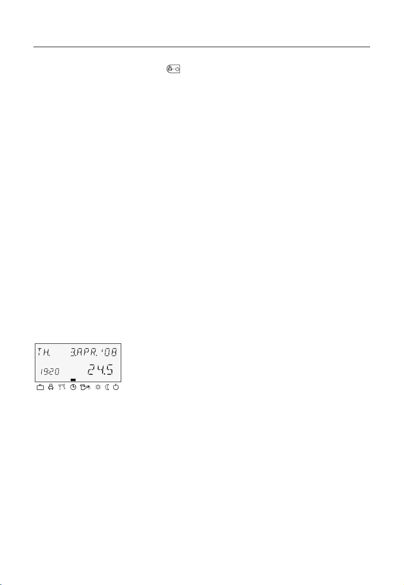
4.1.2.5.3 Automatic mode
In automatic operation, max. three time programs with different
heating operation times are available. They are called up during
C
start-up as factory-set and unlosable default programs P1, P2 or
P3 and can, if necessary, be overwritten with their own switching
times in the "Timeprograms" menu (see 4.2.2 "Timeprograms"
menu, pg. 34).
NOTE
Default programs P2 and P3 cannot be selected until the
PROGRAM = P1 to P3 parameter is enabled in the "System
Parameters" menu. Without enabling, only program P1 is active.
Setting
See 4.1.2.5 "Operating mode" button (basic display) , pg. 16
button.
î and switch to automatic mode.
The active party program has been cancelled.
20 EN2H-0220GE51 R0308
Page 21

SDC / DHC Operation
Disabling / enabling default program P2 to P3
Disabling
"System Parameters" menu, program parameter = P1. All heating
circuits and the hot-water circuit solely refer to the default /
C
individually programmed switching times in the program P1
parameter. Program P1 does not appear in the display in this
operating mode (see 4.2.2 "Timeprograms" menu, pg. 34 and
4.2.3.2 Time program, pg. 52).
Enabling
"System Parameters" menu, program parameter = P1 to P3 (see
4.2.2 "Timeprograms" menu, pg. 34 and 4.2.3.2 Time program,
C
pg. 52).
Display
An active automatic program appears in the basic display with the
current date and time. If default programs P2 and P3 were
enabled, the corresponding symbol,
Â,Ã or Ä, is also
displayed depending on the selected program. The symbols are
only displayed with the time program P1 to P3 active.
Pos: 15 /156-Honeywell/Bedienung/Manueller_Sommerbetrieb @ 1\mod_1207644281166_6.doc @ 9375
4.1.2.5.4 Manual summer operation (excluding heating operation)
With manual summer operation, only the hot-water circuit remains
operation and controls the heat generator temperature based on
C
the specified hot-water temperature and the specified hot-water
switching time program. Heating operation is stopped, and
protection from frost is provided. This feature is only available
when control mode is set to 1.
Setting
See 4.1.2.5 "Operating mode" button (basic display) , pg. 16
Disabling / enabling default programs P2 to P3
Disabling
"System Parameters" menu, program parameter = P1. All heating
circuits and the hot-water circuit solely refer to the default /
C
individually programmed switching times in the time program = P1
parameter. Program P1 does not appear in the display in this
operating mode (see 4.2.2.1 Selection of the control circuit, pg. 35
and 4.2.3.2 Time program, pg. 52).
EN2H-0220GE51 R0308 21
Page 22

Operation SDC / DHC
Enabling
"System Parameters" menu, program parameter = P1 to P3 (see
4.2.2.1 Selection of the control circuit, pg. 35 and 4.2.3.2 Time
C
program, pg. 52).
Display
Manual summer operation appears in the basic display with the
information SUMMER. If default programs P2 and P3 were
enabled, the corresponding symbol,
Â, Ã or Ä, is also
displayed depending on the selected program. The symbols are
only displayed with the time program P1 to P3 active.
Pos: 16 /156-Honeywell/ Bedien ung/ Staendi ger _Hei zbe trieb @ 1 \mod_ 120764 4312 853_6 .doc @ 9 390
4.1.2.5.5 Continuous heating operation
The HEATING operating mode ensures continuous heating
operation without time limitations based on the specified daytime
C
room temperature. Hot-water production occurs continuously
based on the specified daytime hot-water temperature.
NOTE
The HEATING operating mode remains active until another
operating mode is activated.
Display
Activated continuous heating operation appears in the basic
display with the information HEATING.
Pos: 17 /156-Honeywell/Bedien ung/St aendiger _Absenk betrieb @ 1\mod _1207644 346213_6.doc @ 9405
4.1.2.5.6 Continuous lowering operation
The RED. HEATING operating mode causes continuously
reduced heating operation based on the specified lowered room
C
temperature. On the heating circuit levels, the reduced operating
mode ECO (frost-protected deactivation mode) or RED (lowering
mode) is set accordingly. The minimum temperature limit of the
respective heating circuit must be taken into account.
See the "Direct Circuit" or "Mixed Heating Circuit 1" / "Mixed
Heating Circuit 2" menu, reduced parameter = reduced operation
and 12 parameter = minimum temperature limit.
Hot-water production occurs continuously based on the specified
hot-water economy temperature (see "DHW" menu, hot water
parameter = hot water at night).
22 EN2H-0220GE51 R0308
Page 23

SDC / DHC Operation
NOTE
The RED. HEATING operating mode remains active until another
operating mode is activated.
Display
Activated continuous lowering operation appears in the basic
display with the information RED. HEATING.
Pos: 18 /156-Honeywell/ Bedien ung/ Stand by-B etrieb @ 1\m od_1 207644 37991 6_6.do c @ 94 20
4.1.2.5.7 Standby mode
In standby mode, the entire system is switched off and protected
from frost (all frost-protection functions active).
C
Hot-water production is disabled and protected from frost. At
storage temperatures below 5 °C, a reload to up to 8 °C takes
place.
Application
Total deactivation of heating and hot water with full building
protection.
NOTE
The heat generator and hot-water production remain in operation
in case of external demand or demand by other heating circuits
on the bus network. The heating circuit pumps are switched on
briefly every day (pump anti-blocking protection).
The standby mode remains active until another operating mode is
activated.
Display
Activated continuous standby mode appears in the basic display
with the information STANDBY.
Pos: 19 /156-Honeywell/ Bedien ung/ Tas te_Scha ltzei ten_Ur lau bspro gramm e @ 1 \mod_1 207830 15395 7_6 .doc @ 10 720
4.1.2.6 "Switching time programs / Holiday programs" button
Using this button, you can create individualised switching time
programs for heating and hot-water operation and set holiday
mode.
See 4.1.2.6.1 Holiday mode, pg. 24 and 4.2.2 "Timeprograms"
menu, pg. 34.
Pos: 20 /156-Honeywell/Bedien ung/Urla ubsbe trieb @ 1\m od_1207 64407261 9_6.doc @ 9315
EN2H-0220GE51 R0308 23
Page 24

Operation SDC / DHC
4.1.2.6.1 Holiday mode
In holiday mode, the heating circuits can be switched off and
protected from frost or operated based on the settings for the RED.
HEATING operating mode for the duration of the holiday based on
the presetting ("Direct circuit" or "Mixed heating circuit 1" / "Mixed
heating circuit 2" menu, parameter 25 = holiday operating mode).
Setting
► Press button.
The menu-selection level Switching time programs / Holiday
programs appears in the display.
Application
► Turn input button
î to the left.
HOLIDAY appears in the display.
► Press input button
î.
HOLIDAY 01 appears in the display.
► Press input button
î.
The year flashes in the display.
► Set year with the input button
► Press input button
î.
î.
The day on which the holiday is to begin flashes in the display.
► Set the day the holiday will begin with the input button
► Press input button
î.
î.
TIL - - appears in the display.
► Set the day you will return from holiday with the input
button
î.
► Press input button
î.
The desired holiday timeframe is saved.
You can now enter additional holiday timeframes (up to 15 holiday
blocks).
Longer absence while heating operation is active.
24 EN2H-0220GE51 R0308
Page 25

SDC / DHC Operation
Control during
holidays
Cancellation
Factory setting
Setting range
Display
At outside temperatures below the frost-protection limit (see
4.2.3 "System Parameters" menu, pg. 51) the heating circuits are
controlled as follows:
• Without wall devices: Based on a lowered room temperature
specification of 3 °C.
• With wall devices: Based on the room frost-protection limit of
the respective heating circuit of 10 °C (see "Direct Heating
Circuit" or "Mixed Heating Circuit 1", "Mixed heating circuit 2"
menu, parameter 08 = room frost-protection limit).
An active holiday program can be cancelled in case of early
return.
► Press
► Turn input button
button.
î and switch to automatic mode.
The active holiday program has been cancelled.
Current date
Current date... (current date + 250 days)
An active holiday program appears in the basic display with
information on the return date.
Pos: 21 /156-Honeywell/Bedien ung/Tas te_An lageninf ormation @ 1\mod_1 2076444 94728_6 .doc @ 94 50
EN2H-0220GE51 R0308 25
Page 26

Operation SDC / DHC
4.1.2.7 "System information" button
Calls up system information, such as temperatures and counter
¤
data.
The information on the outside temperature appears first after the
¤ button is pressed. Turning the input button î causes the
system temperatures and the counter and consumption states
and operating states of the connected system components to
Exceptions
NOTE
appear. Pressing the input button
setpoint values to appear.
Collector flow temperature: No setpoint
Solar tank temperature: No setpoint
Outside temperature: Averaged value
The displayed information (see the following example) is
independent of the installed or enabled system components and
control circuits.
î causes the respective
26 EN2H-0220GE51 R0308
Page 27

SDC / DHC Operation
Operating overview
Press button
Turn input button to the left Turn input button to the right
Program/operating mode
direct heating circuit/pump status
Program/operating mode
mixed heating circuit 1/pump status
Actuator of
mixed heating circuit 1/status
Program/operating mode
mixed heating circuit 2/pump status
Actuator of
mixed heating circuit 2/status
Program/operating mode
hot-water circuit/pump status
Heat generator
status
Direct heating circuit
pump function/status
Average/current outside
temperature value
Outside temperature
min. to max. (0:00 to 24:00 hours)
Heat generator temperature
setpoint/actual value
Hot-water temperature
setpoint/actual value
Flow temperature
setpoint/actual value
Flow temp of mixed heating circuit 1
setpoint/actual value
Flow temp of mixed heating circuit 2
setpoint/actual value
Variable input 1
setpoint/actual value
Variable input 2
setpoint/actual value
Variable output 1
function/operating state
Variable output 2
function/operating state
Variable input 2
setpoint/actual value
Operating hours
Activations of heat generator
EN2H-0220GE51 R0308 27
Page 28

Operation SDC / DHC
r
Setting time fo
automatic return
Setting range
Factory setting
4.1.2.8 "Manual mode" / "Emission measurement" button
4.1.2.8.1 Manual mode
C
Application
NOTE
¤ button is pressed and held for approx. 3 s, the INFO
If the
TIME parameter appears.
With this parameter, the time it takes for automatic return to the
basic display can be specified.
OFF No return. The last selected information display
continuously remains in the basic display until the
next change.
1 ... 10 min Automatic return from the information level after the
specified time (in 0.5 minute increments).
OFF
Pos: 22 /156-Honeywell/Bedien ung/Tas te_Hand betrie b_Emmiss ionsmess ung @ 1\mo d_12076 44568369 _6.doc @ 9465
Pos: 23 /156-Honeywell/Bedien ung/Han dbetrieb @ 1\mod_ 1207644 610119_6 .doc @ 9480
If this button is pressed and held longer than 5 s in the basic
display, the controller is switched to manual mode. In this
operating mode, the required heat generator temperature is
specified manually with the input button
î according to the
respective heating need.
A controller set to manual mode has no effect in heat circuit
expansion.
The heat generator setpoint is set between the minimum and
maximum heat generator temperatures and appears flashing at
C
the bottom left-hand side. The current heat generator temperature
appears statically on the right-hand side in the basic display. The
set switching differential corresponds to the value of automatic
control and is symmetrical to the set value.
Controller malfunctions (emergency operation), errors
The maximum heat generator temperature limit is paramount to
the heat generator switching differential and stops the heat
generator in case of exceedance.
With control devices operated purely as a heating circuit
expansion, the setting of the temperature has no effect.
28 EN2H-0220GE51 R0308
Page 29

SDC / DHC Operation
The last value to which the control device adjusted the heat
generator temperature appears as a recommendation.
Cancellation
Press button or button, to return to the last selected
operating mode.
Pos: 24 /156-Honeywell/Bedienung/Emmissionsmessung @ 1\mod_1207644670916_6.doc @ 9495
4.1.2.8.2 Emission measurement (not with district heating controllers)
ATTENTION
Emission measurements may only be carried out by the
chimney sweep.
Pressing the button controls the heat generator for a duration
of 20 min based on the set maximum temperature limit. The
remaining time is displayed and counted down.
With two-stage heat generators, both stages are in operation
(measurement at nominal output).
Function
The heat generator is adjusted to the maximum heat generator
temperature. All heating circuits and the hot-water production
adjust their setpoint to the respective maximum temperature.
ATTENTION
There is a danger of scalding by hot water, as the hot-water
temperature can exceed the set setpoint temperature.
Application
Cancellation
Emission measurement by the chimney sweep.
Emission measurement can be cancelled at any time with the
or
button.
Pos: 25 /156-Honeywell/Bedien ung/He izkurve @ 1 \mod_ 12076444 24181_6 .doc @ 9435
EN2H-0220GE51 R0308 29
Page 30

Operation SDC / DHC
4.1.2.9 Heating curve
Determines the heating curve for the heating circuits.
The heating curve describes the relationship of the flow
C
temperature change to the outside temperature change. With a
larger heating surface, such as with floor heaters, the heating
curve has a less extreme slope than with a smaller heating
surface (e.g. radiators).
The set value refers to the lowest outside temperature used for
heat demand calculation.
ATTENTION
This parameter must be set by the technician and should no
longer be changed.
Setting
► Press and hold input button î for 3 s.
Setting range
► Turn the input button
MC-1 or MC-2) and confirm it by pressing the input button
î to select the desired heating circuit (HC,
î.
The design temperature (system) appears at the bottom righthand side of the display.
► Press input button
î.
The slope of the heating curve appears at the bottom left-hand
side of the display.
► Set the flashing heating curve value by turning the input button
î (design temperature also flashes and is changed
automatically depending on the slope of the heating curve).
► Confirm by pressing the input button
Alternative: Automatic acceptance of the value after the set
information time (see 4.1.2.7 "System information" button, pg. 26).
► Press
button to return to the basic display.
0,2 ... 3,5
î.
30 EN2H-0220GE51 R0308
Page 31

SDC / DHC Operation
Factory setting
4.2 Menu-selection level
Direct heating circuit (HC) = 1,5
Mixed heating circuit 1
(MC-1) = 1
Mixed heating circuit 2
(MC-2) = 1
x
a
x Boiler / flow temperature [°C]
y Outside temperature [°C]
a T
room
[°C]
Pos: 26 /156-Honeywell/Bedien ung/Men ue_Ausw ahlebene @ 1\mod_1 2076447 10588_6 .doc @ 9510
y
The control device contains a menu-selection level that is
structured differently, depending on the respective device version.
Access
► Press and hold input button î for approx. 3 s.
The menu selection always begins with the TIME – DATE
menu.
► Turn input button
► Press input button
î to select additional menus.
î to confirm the selected menu.
EN2H-0220GE51 R0308 31
Page 32

Operation SDC / DHC
The menu functions are described in the following:
Program-
Configuration Configuration
ming
Parameter
01 Time Language
02 Year Time program Legionella-
Time - Date
System parameter
selection
Hot water
Nighttime
hot water
Direct heating
circuit
Heating
curve
Mixed heating
circuit 1
Heating
curve
Mixed heating
circuit 2
Heating
curve
Reduced Reduced Reduced
protection
day
03 Day -
Month
04 Change Summer /
Operating
mode
– Heating
system
Heating
system
Heating
system
– – – –
Heat limit
05 – – – – – –
06 – – – – – –
07 – – – – – –
23 – Parameter
– – – –
reset
Heating
circuit
name
– – – Heating
circuit
name
Heating
circuit
name
Heating
circuit
name
Pos: 27 /156-Honeywell/ Bedien ung/ Menue_U hr- Datum @ 1\mod _1207 6447 49744_ 6.do c @ 95 25
32 EN2H-0220GE51 R0308
Page 33

SDC / DHC Operation
4.2.1 "Time - Date" menu
The following current calendar values can be specified in this
menu:
• Time
• Year
• Day - Month
• Time change mode (summer / winter time)
NOTE
All listed daytime values are set at the factory and generally do
not need to be updated.
An internal, pre-programmed calendar ensures automatic time
change on the annually recurring summer / winter time switchover
dates. If necessary, the automatic time change can be
deactivated. The current weekday, Mo to Su is determined from
the calendar date and does not need to be set.
Application
Access
Setting
Corrections for rare fault cases
See 4.2 Menu-selection level, pg. 31
► Turn input button î and select the "Time - Date" menu.
► Turn input button
î and select the desired calendar value
(time, year, day - month, change).
► Press input button
turning the input button
► Press input button
► Turn input button
î and change the corresponding value by
î.
î to confirm the set value.
î to select and change additional calendar
values.
Returning
Returning to the basic display takes place by pressing the
button or automatically after the set information time (see
4.1.2.7 "System information" button, pg. 26).
Pos: 28 /156-Honeywell/Bedien ung/Men ue_Scha ltzeite n @ 1\mod _1207644 798369_ 6.doc @ 9 540
EN2H-0220GE51 R0308 33
Page 34

Operation SDC / DHC
4.2.2 "Timeprograms" menu
Individualised switching time programs for heating and hot-water
operation can be created in this menu. Here, the factory-set
default programs P1 (and, if enabled, P2 and P3 as well) of each
heating circuit and the hot-water circuit are overwritten by
individualised switching times and temperature specifications.
This is especially advantageous if correspondingly adapted
heating programs are to be created in case of periodically
recurring assignments with different assignment times (e.g. shift
work). Max. three heating cycles, each with a switch-on and
switch-off time, are available for each day of the week for
programming switching times. Each heating cycle can also be
combined with a freely-selectable temperature specification.
NOTE
The default programs are not lost when overwritten by individually
created programs. Individualised programs, however, are deleted
when default programs are reloaded and must be recreated. For
this reason, individualised switch-on / switch-off times and
temperature specifications should always be entered in the tables
provided for this purpose (see 5 Log, pg. 60).
Access
Returning
Press button.
Returning to the basic display takes place by pressing the
button or automatically after the set information time (see
4.1.2.7 "System information" button, pg. 26).
Pos: 29 /156-Honeywell/Bedien ung/Aus wahl_de s_Regelk reises @ 1\mod_120 7644837 697_6. doc @ 95 55
34 EN2H-0220GE51 R0308
Page 35

SDC / DHC Operation
4.2.2.1 Selection of the control circuit
After accessing the "Timeprograms" menu, the desired control
circuits can be selected with the input button
î in the following
sequence:
• Direct heating circuit (HC)
• Mixed heating circuit 1 (MC-1)
• Mixed heating circuit 2 (MC-2)
• Hot-water circuit (DHW)
► Press input button
î to access the selected circuit.
Pos: 30 /156-Honeywell/Bedien ung/Aus wahl_de s_Program ms @ 1\m od_12076 4489508 8_6.doc @ 9570
4.2.2.2 Selection of the program
If the switching time programs P2 and P3 have been enabled (see
"System Parameter" menu, program parameter = P1 to P3), the
program selection appears.
If switching time programs P2 and P3 are disabled, program
selection is automatically skipped (see "System Parameters"
menu, program parameter = P1).
Pos: 31 /156-Honeywell/Bedienung/Auswahl_von_Wochentag_und_Zyklus @ 1\mod_1207644995228_6.doc @ 9585
4.2.2.3 Selection of day of the week and cycle
Once the program is selected, the first cycle of the first day of the
week (MO 1) and the relevant section in the top time bar flash.
The other cycles are selected by turning the input button
confirmed by pressing the input button
î.
Pos: 32 /156-Honeywell/Bedienung/Programmieren_von_Schaltzeiten_und_Zyklustemperaturen @ 1\mod_1207645043306_6.doc @ 9600
î and
EN2H-0220GE51 R0308 35
Page 36

Operation SDC / DHC
4.2.2.4 Programming switching times and cycle temperatures
Pos: 33 /156-Honeywell/Bedien ung/Eins chalt zeit @ 1\m od_12076 4516435 3_6.doc @ 9615
4.2.2.4.1 Switch-on time
The switch-on time is the start of heating or, with enabled switchon optimisation, the start of assignment.
After selecting the day of the week and the corresponding cycle,
the respective switch-on time appears flashing and can be set
with the input button
î. The time bar in the top part of the display
provides an overview of all programmed cycles between 0:00 and
24:00 hours on the selected day of the week.
NOTE
The switch-on time cannot be set below the switch-off time of a
previous cycle or below 0:00 hours of the selected day of the
week.
If the switch-on time is changed, the corresponding time bar
display is adjusted to the left-hand side.
If the switch-on time is made equal to the switch-off time, the
corresponding cycle is deleted. A subsequent cycle is
automatically shifted to the position of the deleted cycle upon
acceptance.
With subsequent insertion of a cycle that has been bumped up,
the corresponding day of the week must be reprogrammed.
A flashing switch-on time is accepted by pressing the input button
î.
Pos: 34 /156-Honeywell/Bedienung/Ausschaltzeit @ 1\mod_1207645241572_6.doc @ 96 30
4.2.2.4.2 Switch-off time
The switch-off time is the end of heating or, with enabled switchoff optimisation, the end of assignment.
Once the switch-on time is accepted, the associated switch-off time
appears flashing and can be changed with the input button
î. The
time bar in the top part of the display provides an overview of all
programmed cycles between 0:00 and 24:00 hours on the
selected day of the week.
36 EN2H-0220GE51 R0308
Page 37

SDC / DHC Operation
NOTE
The switch-off time cannot be set higher than the switch-on time
of a subsequent cycle.
If the switch-on time is changed, the corresponding time bar
display is adjusted to the right-hand side.
If the switch-off time is made equal to the switch-on time, the
corresponding cycle is deleted. A subsequent cycle is
automatically shifted to the position of the deleted cycle upon
acceptance.
With subsequent insertion of a cycle that has been bumped up,
the corresponding day of the week must be reprogrammed.
A flashing switch-off time is accepted by pressing the input button
Pos: 35 /156-Honeywell/ Bedien ung/ Zyklus tem perat ur @ 1 \mod_1 207645 3592 13_6 .doc @ 96 45
4.2.2.4.3 Cycle temperature
Once the switch-off time is accepted, the associated cycle
temperature appears flashing and can be changed immediately
with the input button
temperature is always based on the desired room temperature;
with the hot-water circuit, it is based on the desired normal hotwater temperature in the selected cycle.
A flashing cycle temperature is accepted by pressing the input
button
î.
At the same time, the last called-up cycle appears flashing so that
it may be monitored; additional cycles can then be selected
directly and edited in the same way in the order: switch-on time,
switch-off time, cycle temperature.
Pos: 36 /156-Honeywell/Bedienung/Schaltzeitenprogrammierung_gesperrt @ 1\mod_1207645477385_6.doc @ 9660
î.
î. With heating circuits, the displayed cycle
EN2H-0220GE51 R0308 37
Page 38

Operation SDC / DHC
Switching time programming (programs P2 and P3 disabled)
Upon accessing the menu-selection level, the "Timeprograms"
menu always appears first.
Enabling of programs P2 and P3 in the "System Parameters"
menu (see 4.2 Menu-selection level, pg. 31).
Select
heating circuit:
Select day
and cycle:
Change:
Change:
Change:
HC MC -1 MC -2 DHW
MoHcy-1
Start of
heating
End of
heating
Temperature
MoHcy-2
Monitoring
MoHcy-3
Only appears if there are switching
times in the second heating cycle.
HC Direct heating circuit
MC-1 Mixed heating circuit 1
MC-2 Mixed heating circuit 2
DHW Hot-water heating circuit
Hcy Heating cycle
Default
time
TuHcy-1
We
Th
Su-
Fr
Hcy-3
Sa
Return to the basic display:
Copy
circuit
Copy
day
Return:
3 s
38 EN2H-0220GE51 R0308
Page 39

SDC / DHC Operation
Default switching time program (P1) for heating and hot
water
Uniform, continuous heating and hot-water operation on all days
of the week
Default program P1
Heating operation Heating circuit Day
from to
Heat generator heating
Mo to Su 6:00 22:00
circuit
Hot-water circuit Mo to Su 5:00 22:00
Mixed heating circuit 1 / 2 Mo to Su 6:00 22:00
Pos: 37 /156-Honeywell/Bedien ung/Sc haltzei tenprog rammierun g_frei geschal tet @ 1\mo d_12076 45530166 _6.doc @ 9675
EN2H-0220GE51 R0308 39
Page 40

Operation SDC / DHC
Switching time programming (program P2 and P3 enabled)
Upon accessing the menu-selection level, the "Timeprograms"
menu always appears first. Enabling of programs P2 and P3 in
the "System Parameters" menu (see 4.2 Menu-selection level,
pg. 31).
Select
heating circuit:
Select
program:
Select day
and cycle:
Change:
Change:
Change:
HC
P1 P2 P3
MoHcy-1
Start of
heating
End of
heating
Temperature
MC -1 MC -2 DHW
MoHcy-2
Monitoring
HC Direct heating circuit
MC-1 Mixed heating circuit 1
MC-2 Mixed heating circuit 2
DHW Hot-water heating circuit
Hcy Heating cycle
Default
time
MoHcy-3
Only appears if there are switching
times in the second heating cycle
TuHcy-1
We
Su-
Th
Hcy-3
Fr
Sa
Return to the basic display:
Copy
circuit
Copy day
Return:
3 s
40 EN2H-0220GE51 R0308
Page 41

SDC / DHC Operation
Default program P1
Heating operation Heating circuit Day
from to
Heat generator heat-
Mo to Su 6:00 22:00
ing circuit
Hot-water circuit Mo to Su 5:00 22:00
Mixed heating
Mo to Su 6:00 22:00
circuit 1 / 2
Default program P2
Heating operation Heating circuit Day
from to from to
Mo to Th 6:00 8:00 16:00 22:00
Boiler heating circuit
Fr 6:00 8:00 13:00 22:00
Sa to Su 6:00 22:00
Mo to Th 5:00 8:00 15:30 22:00
Hot-water circuit
Fr 5:00 8:00 12:30 22:00
Sa to Su 6:00 23:00
Mo to Th 6:00 8:00 16:00 22:00
Mixed heating
circuit 1 / 2
Fr 6:00 8:00 13:00 22:00
Sa to Su 7:00 23:00
Default program P3
Heating operation Heating circuit Day
from to
Mo to Fr 7:00 18:00 Heat generator heat-
ing circuit
Sa to Su Reduced
Mo to Su 6:00 18:00 Hot-water circuit
Sa to Su Reduced
Mo to Su 7:00 18:00 Mixed heating
circuit 1 / 2
Sa to Su Reduced
Pos: 38 /156-Honeywell/Bedien ung/Kopi eren_ von_Scha ltzeite nprogram men_ Tage @ 1\mo d_12076 45726103 _6.doc @ 96 90
EN2H-0220GE51 R0308 41
Page 42

Operation SDC / DHC
4.2.2.4.3.1 Copying switching time programs (days)
Block programming enables the switching times and cycle
temperatures of any day of the week to be copied
1 – To any days within the week (Mo, Tu, We, ..., Su)
2 – To all weekdays (Mo to Fr)
3 – To the weekend (Sa to Su)
4 – To the entire week (Mo to Su)
Calling up the copy function (days)
See flowcharts on pg. 44
Source day
► Press input button î to confirm the copy function.
► Turn input button
î to select the source day (MO to SU) to be
copied.
The respective automatic program P1 (P2, P3) of the source
day is copied in the display with the time switch symbol and
the program index.
Target day
► Press input button î to confirm the source day.
The source day appears flashing.
► Turn input button
confirm by pressing the input button
î to select the following setting values and
î:
• The following target days (Mo to Su) individually
• All days of the week (1 to 7) as a week block
• All weekdays (1 to 5) as a weekday block
• The weekend days (6 to 7) as a weekend block
Acceptance is confirmed by acknowledging DAY COPY OK.
After acknowledgement, the following target days appear one
after another automatically with each additional press of the input
button
î and can be skipped and accepted if necessary.
Pressing the
button causes an immediate return to the basic
display.
NOTE
Only complete days with all cycles and temperature specifications
and the respective program can be copied.
42 EN2H-0220GE51 R0308
Page 43

SDC / DHC Operation
Pos: 39 /156-Honeywell/Bedien ung/Kopi eren_ von_Scha ltzeite nprogram men_Heizk reis e @ 1\mod_ 1207645 787619_6 .doc @ 970 5
4.2.2.4.3.2 Copying switching time programs (heating circuits)
Block programming also enables the copying of all switching
times and temperature specifications of a heating circuit to
another heating circuit.
Calling up the copy function (heating circuits)
See flowcharts on pg. 44
Source circuit
► Press input button î to confirm the copy function.
Target circuit
NOTE
► Turn input button
î to select the source circuit to be copied
(HC, MC-1, MC-2, DHW).
If automatic program P1, P2 or P3 (see "System Parameter"
menu, PROGRAM parameter = P1 to P3) was enabled, the
desired switching time program P1, P2 or P3 of the source
circuit can be selected. If not enabled, program selection is
skipped.
► Press input button î, to confirm the source circuit.
Based on the same chart, the desired target circuit and, if
enabled, the desired program can be selected and accepted.
Acceptance is confirmed by acknowledging COPY OK. The copy
function is then called up again to copy additional circuits, if
necessary.
Heating circuits cannot be copied to hot-water circuits or the reverse due to the different temperature specifications. If a heating
circuit (HC, MC-1, MC-2) is selected as the source circuit, the hotwater circuit (DHW) switches off as the target circuit.
A hot-water circuit as the source circuit is also the target circuit. In
this case, only switching time programs P1 to P3 are copied
among one another.
Pressing the
button causes an immediate return to the basic
display.
Pos: 40 /156-Honeywell/Bedienung/Blockprogrammierung @ 1\mod_1207645891978_6.doc @ 9720
EN2H-0220GE51 R0308 43
Page 44

Operation SDC / DHC
Block programming
The copy function enables a source day to be copied to any target
days or to all days of the week (week programming). All cycles of
the source day are copied. Individual heating cycles cannot be
copied.
ö
Select
heating circuit:
Select program:
Select
copy function:
HC
ö
î
P1 P2 P3
ö
î
Mo
Hcy-1
Mo
Hcy-2
HC Direct heating circuit
MC-1 Mixed heating circuit 1
MC-2 Mixed heating circuit 2
DHW Hot-water heating circuit
1) Program selection for source and target circuits are
skipped if programs P2 and P3 are disabled in the
"System Parameter" menu.
MC -2MC -1
Mo
Hcy-3
DHW
1)
Tu
Hcy-1
We
Th
Fr
Sa
Default
time
Su
Hcy-3
Copy
circuit
Copy day
44 EN2H-0220GE51 R0308
Page 45

SDC / DHC Operation
Copy day
Select
source day:
Example: Monday
Select
first target day:
Example: Tuesday
Copy source day
to first target day:
Acknowledge:
Select
second target day:
Example: Wednesday
Copy source day
to second target day
Acknowledge:
Copy
from Mo
Copy Mo
to Tu
Copy
day OK
Copy Mo
to We
Copy
day OK
Mo ... Su
Source day
1 target day or
1-7 (Mo ... Su) or
1-5 (Mo ... Fr) or
6-7 (Sa ... Su)
Tuesday as with Monday
Source day
Second target day
Wednesday as with Monday
Select and copy other
target days if necessary
Return to the basic display:
EN2H-0220GE51 R0308 45
Page 46

Operation SDC / DHC
Pos: 41 /156-Honeywell/Bedien ung/Kopi eren_ von_Heizk reisen @ 1\mod_12 07645944 978_6 .doc @ 973 5
Copying heating circuits
NOTE
Heating circuits cannot be copied to hot-water circuits since they
have different cycle temperatures: If a heating circuit is selected
as the source circuit, the hot-water circuit can no longer be called
up as the target circuit. The hot-water circuit as the source circuit
is also the target circuit. In this case, only programs of the hotwater circuit are copied among one another if they were enabled
in the "System Parameter" menu.
Select
copy function:
Select
source circuit:
Select
source circuit
program:
Select
target circuit:
Select
target circuit
program:
Copy:
Acknowledge:
Exit:
HC MC-1 MC-2 DHW
Source circuit
HC
Source circuit
HC P1
Target circuit
HC
Target circuit
MC -2 P1
Copy
-OK-
Source circuit
MC -1
Source circuit
MC -1 P2
Target circuit
MC -1
Target circuit
MC -2 P2
Program P1 (direct heating circuit) =
Program P2 (mixed heating circuit 2)
Copy additional heating circuits
if necessary
Source circuit
MC -2
Source circuit
MC -2 P3
Target circuit
MC -2
Target circuit
MC -2 P3
Default
time
1)
1)
Copy
circuit
Basic display
46 EN2H-0220GE51 R0308
Page 47

SDC / DHC Operation
HC Direct heating circuit
MC-1 Mixed heating circuit 1
MC-2 Mixed heating circuit 2
DHW Hot-water heating circuit
1) Program selection for source and target circuits are
skipped if programs P2 and P3 are disabled in the
"System Parameter" menu.
Pos: 42 /156-Honeywell/Bedien ung/Rue ckladen _von_Sta ndardp rogramm en @ 1\mod_1 20764607 7806_6 .doc @ 9750
4.2.2.4.4 Reloading default programs
See flowchart on pg. 49
Individually created switching time program P1, P2 or P3 can be
overwritten with the original default switching time program P1, P2
or P3.
For this purpose, select the DEFAULT-TIME function within the
heating circuit selection after accessing the "Timeprograms"
menu.
After confirming by pressing the input button
î, the circuit
dedicated to reloading appears flashing (HC, MC-1, MC-2, ALL).
If the automatic programs P1, P2 and P3 (see "System
Parameter" menu, program parameter = P1 to P3) were enabled,
the desired switching time program P1, P2 or P3 of the heating
circuit affected by the reload can be selected. If not enabled,
program selection is skipped.
Resetting
Resetting then occurs by pressing and holding the input button
approx. 5 s until acknowledgement appears in the display.
Resetting is confirmed by acknowledging COPY OK.
The DEFAULT-TIME function is then called up again to replace
other circuits with their default programs if necessary.
EN2H-0220GE51 R0308 47
Page 48

Operation SDC / DHC
ATTENTION
With the setting value ALL, all heating circuits and the hotwater circuit are overwritten with their default switching
times with regard to the selected program.
When overwriting occurs, individually created switching time
programs are permanently lost and must be recreated from
scratch.
Pressing the button causes an immediate return to the basic
display.
48 EN2H-0220GE51 R0308
Page 49

SDC / DHC Operation
Reloading default programs
Switching time programs P2 and P3 disabled
HC Direct heating circuit
MC-1 Mixed heating circuit 1
MC-2 Mixed heating circuit 2
DHW Hot-water heating circuit
EN2H-0220GE51 R0308 49
Page 50

Operation SDC / DHC
Reloading default programs
Switching time programs P2 and P3 enabled
DHW
HC Direct heating circuit
MC-1 Mixed heating circuit 1
MC-2 Mixed heating circuit 2
DHW Hot-water heating circuit
Pos: 43 /156-Honeywell/ Bedien ung/ Menue_S yst empara me ter @ 1\m od_120 76461 5151 0_6.do c @ 9 765
50 EN2H-0220GE51 R0308
Page 51

SDC / DHC Operation
4.2.3 "System Parameters" menu
The system parameters refer to general limiting parameters and
specification values within the heating system.
Access
Returning
See 4.2 Menu-selection level, pg. 31
Returning to the basic display takes place by pressing the
button or automatically after the set information time (see
4.1.2.7 "System information" button, pg. 26).
Pos: 44 /156-Honeywell/ Bedien ung/ Sprac hwah l @ 1\mod _120 76461 89369_ 6.doc @ 9 780
4.2.3.1 Language selection
Several languages can be selected for all information that
appears in the display.
After selecting the language and confirming it by pressing the
input button
î, additional communication takes place in the
respective language.
Setting values
DE German
GB English
FR French
IT Italian
NL Dutch
ES Spanish
PT Portuguese
HU Hungarian
CZ Czech
PL Polish
RO Romanian
RU Russian
TR Turkish
S Swedish
N Norwegian
Factory setting
German
Pos: 45 /156-Honeywell/Bedien ung/Ze itprog ramm @ 1\mod_ 12076462 19572_6 .doc @ 9795
EN2H-0220GE51 R0308 51
Page 52

Operation SDC / DHC
4.2.3.2 Time program
This parameter specifies enabling of the switching time programs
for program selection and for individualised switching time
programming. In the state of delivery, only one switching time
program is enabled. This achieves simplification of operation with
a large portion of applications for which only one switching time
program is used.
Set values
P1 Program 1 = enabled, programs 2 and 3 = disabled
P1
All three programs enabled
to P3
Factory setting
Effects
P1
In contrast to the previous description, the following setting
options are available when programs P1 to P3 are enabled:
• Operating mode selection: In the AUTOMATIC and SUMMER
operating modes, switching time program P1, P2 or P3 can be
selected.
• Switching time programming: With switching time pro-
gramming, the three switching time programs, P1 to P3, can
be selected for each heating circuit.
Pos: 46 /156-Honeywell/Bedien ung/Bedi enmodu s @ 1\mod _1207646 570291_6 .doc @ 9840
4.2.3.3 Operating mode
Two operating modes can be selected. They determine whether
the operating mode, the daytime temperature and the night-time
temperature apply for all heating circuits or can be specified
individually for each heating circuit.
Setting range
Set values
1, 2
1 The selected setting applies for all heating circuits together.
2 Each heating circuit can be assigned an individualised set-
ting.
Factory setting
1
Pos: 47 /156-Honeywell/Bedien ung/Ind ividuel le_Tage s-Raum temperat ur @ 1\m od_12076 4660188 5_6.doc @ 9855
52 EN2H-0220GE51 R0308
Page 53

SDC / DHC Operation
4.2.3.3.1 Individualised daytime room temperature for each heating
circuit
Setting
► Press
¥ button.
► Select desired heating circuit (HC, MC-1 or MC-2) by turning
C
the input button
î.
► Confirm selected circuit by pressing the input button
► Set flashing room temperature specification to the desired
value by turning the input button
► Confirm set value by pressing the
î.
¥ button.
Alternative: Automatic acceptance of the value after the set
information time (see 4.1.2.7 "System information" button, pg. 26).
Setting range
Factory setting
5 ... 30 °C
20 °C
Pos: 48 /156-Honeywell/Bedienung/Individuelle_Nacht-Raumtemperatur @ 1\mod_1207646643760_6.doc @ 9870
4.2.3.3.2 Individualised night-time room temperature for each heating
circuit
Setting
► Press
¦ button.
► Select desired heating circuit (HC, MC-1 or MC-2) by turning
C
the input button
î.
► Confirm selected circuit by pressing the input button
► Set flashing room temperature specification to the desired
value by turning the input button
î.
î.
î.
► Confirm set value by pressing the
¦ button.
Alternative: Automatic acceptance of the value after the set
information time (see 4.1.2.7 "System information" button, pg. 26).
Setting range
Factory setting
5 ... 30 °C
16 °C
Pos: 49 /156-Honeywell/Bedien ung/Ind ividuel le_Be triebsar t @ 1\mod _120764 6682213 _6.doc @ 988 5
EN2H-0220GE51 R0308 53
Page 54

Operation SDC / DHC
4.2.3.3.3 Individualised operating mode for each heating circuit
Each heating circuit can be assigned an individualised operating
mode.
Setting
► Press button.
► Select desired heating circuit (HC, MC-1 or MC-2) by turning
the input button
C
► Confirm selected circuit by pressing the input button
î.
î.
► Select flashing operating mode by turning the input button
► Confirm set operating mode by pressing the
input button
î.
► With short-term operating modes (ABSENT, PARTY), set
desired target value by turning the input button
set value by pressing the input button
Alternative: Automatic acceptance of the value after the set
information time (see 4.1.2.7 "System information" button, pg. 26).
Pos: 50 /156-Honeywell/Bedien ung/Somm er_Heizg renze @ 1\mod_1 20764705 8244_6 .doc @ 9900
4.2.3.4 Summer / Heating limit
This parameter specifies the end of heating operation depending
on the outside temperature based on the following criteria:
Quick increase in outside temperature
If the averaged outside temperature is below the set value and
the current outside temperature is 2 K above the set value,
heating operation is interrupted.
Slow increase in outside temperature
Deactivation is also initiated when the averaged and current
outside temperature exceeds the set value.
î.
button or the
î and confirm
î.
54 EN2H-0220GE51 R0308
Page 55

SDC / DHC Operation
Undoing deactivation
Deactivation is undone when the averaged and current outside
temperature exceeds the set value by 1 K.
The summer deactivation function is undone:
• In case of an outside sensor defect
• In case frost protection is active
NOTE
During deactivation phases (standby mode, manual summer
operation, summer deactivation) lasting longer than 24 hours all
pumps are switched on for approx. 20 s and the mixers are
temporarily opened during this time to protect against blocking by
corrosion.
In connection with a second outside sensor, the current averaged
outside temperature is accepted for summer deactivation if the
average value of both sensors is specified during outside sensor
assignment.
Active summer deactivation is represented by a beach umbrella
symbol in the basic display.
Only active in the AUTOMATIC operating mode.
Factory setting
Setting range
20 °C
OFF, set value of system frost protection to 40 °C
Pos: 51 /156-Honeywell/Bedien ung/Par ameter -Reset @ 1\mod_12 07647099 619_6.d oc @ 9915
4.2.3.5 Parameter reset
With the reset parameter, it is possible to reset any inadvertently
made changes in the parameter menu to the factory setting.
ATTENTION
A reset should only be carried out if all individually entered
values are to be replaced by the values specified at the
factory.
Setting
► When the PARAM. RESET display flashes, press the input
î.
button
SET flashes in the display.
► Press and hold the input button
î for 5 s.
EN2H-0220GE51 R0308 55
Page 56

Operation SDC / DHC
If a reset is carried out, the RESET OK confirmation appears
briefly. Verification is then started with a call-up of the first
parameter in the respective menu once again.
After the parameter values are reset, a return to the first
parameter in the "System Parameter" menu occurs.
Pos: 52 /156-Honeywell/Bedienung/Menue_Warmwasser @ 1\mod_1207647138228_6.doc @ 9930
4.2.4 "DHW" menu
This menu contains all parameters required to program the hotwater circuit, except the hot-water switching time programs.
Pos: 53 /156-Honeywell/Bedien ung/Warm wassert -Nachtt empera tur @ 1\mo d_120764 7183619 _6.do c @ 9945
4.2.4.1 Night-time hot-water temperature
This parameter specifies the temperature in the hot-water
generator between the operational-readiness times in automatic
mode.
Factory setting
Setting range
NOTE
40 °C
5 °C to set normal hot-water temperature value
If a hot-water thermostat (see parameter 05 = transducer for hotwater circuit) is used to detect the hot-water temperature, this
parameter is skipped.
Pos: 54 /156-Honeywell/ Bedien ung/ Legi onellens chu tz_Ta g @ 1 \mod_ 12076 4721 8838_6 .doc @ 9 960
4.2.4.2 Legionella protection day
Factory setting
Setting range
Set values
OFF
OFF, MO to SU, ALL
OFF The legionella protection function is not active.
MO to SU Legionella protection is activated on the selected
day of the week at the legionella protection time set
in the following parameter.
ALL The legionella protection function is activated daily
at the legionella protection time set in the next
parameter.
56 EN2H-0220GE51 R0308
Page 57

SDC / DHC Operation
NOTE
4.2.5 "Direct Heating Circuit" / "Mixed Heating Circuit 1" / "Mixed
4.2.5.1 Reduced operation
Factory setting
Setting range
Set values
Application
If a hot-water thermostat (see 05 parameter = transducer for hotwater circuit) is used to detect the hot-water temperature, these
parameters are skipped.
Pos: 55 /156-Honeywell/Bedien ung/Men ues_Dir ekheizkr eis_ Mischhei zkreis @ 1\mod_12 07647253 025_6.do c @ 9975
Heating Circuit 2" menu
These menus contain all parameters required to program the
heating circuit, except the switch time programs. Max. one direct
heating circuit and two mixed heating circuits (mixed heating
circuit 1 and mixed heating circuit 2) are available as heating
circuits.
The following described heating circuit parameters are available
separately for setting for each heating circuit.
Pos: 56 /156-Honeywell/Bedien ung/Red uzier ter_Betr ieb @ 1\mo d_120764 7295322 _6.doc @ 9990
During reduced operation, you can select between two operating
modes.
ECO
ECO, RED
RED (lowering operation)
The heating circuit pump of the direct heating circuit continues
functioning during reduced operation (see 4.2.3.2 Time program,
pg. 52). The flow temperature is determined based on the lowered
room temperature from the associated reduced heating curve.
The set maximum temperature is not undershot.
Building with minimal insulation values and high cooling loss.
EN2H-0220GE51 R0308 57
Page 58

Operation SDC / DHC
ECO (switch-off operation)
During reduced operation, the direct heating circuit is switched off
completely with outside temperatures above the set frostprotection limit. The maximum heat generator temperature is not
functional. The heating circuit pump is switched off after a delay to
avoid safety deactivation by reheating the heat generator (pump
follow-up).
If the outside temperature is or becomes lower than the specified
outside temperature frost-protection limit, the controller switches
from deactivated (deactivation mode) to lowered lowering
operation and controls the heating circuit temperature based on
the set lowering curve taking the set minimum heat generator
specification into account.
Application
NOTE
Building with high insulation values (full heating protection).
The mode set here also applies for the ABSENT and RED.
HEATING operating modes.
Pos: 57 /156-Honeywell/Bedienung/Heizsystem @ 1\mod_1207647329666_6.doc @ 10005
4.2.5.2 Heating system
This parameter refers to the type of the heating system (floor,
radiator or convector heating) and can be matched to the
exponent of the respective heat distributor. Using its progressive
characteristics, the set value determines the curve characteristics
of the heating curve of the direct heating circuit and compensates
for the losses in output in the low-temperature range with it.
The following settings are recommend depending on the type of
heating system:
1,1 Slightly progressive heating curves for floor or other
area heating.
1,3 Progressive standard heating curves for all radiator
heating with m-values between 1.25 and 1.35.
2 Progressive heating curves for convector and
baseboard heating.
>3 Heavily progressive heating curves for general ventilator
applications with high starting temperatures.
58 EN2H-0220GE51 R0308
Page 59

SDC / DHC Operation
r
r
r
Factory setting
Setting range
4.3 Error messages
Sensor erro
messages
Heat generator erro
messages
Logical erro
messages
Bus error messages
1,3 (radiator systems)
1,1 (floor heating) with mixed heating circuits
1 ... 10
Pos: 58 /156-Honeywell/Bedien ung/St oermeldun gen @ 1\mo d_120764 7364681 _6.do c @ 10020
ATTENTION
Inform the heating technician whenever any fault messages
are output.
The control device contains substantial error-notification logic.
The error messages appear in continuous alteration with the basic
display. Multiple errors that occur at the same time appear one
after another in the order in which they occurred. The following
types of error message exist:
Sensor measured values that do not lie in the measurement
range are evaluated as an interruption or short-circuit. They
appear depending on the type and allocation with fault code 10 to
20 and index 0 for short-circuit or 1 for interruption.
These error messages evaluate the respective switching status.
They appear depending on the type and allocation with fault code
30 to 40 and index 0, 1 or 2.
These error messages evaluate the control result to be expected.
They appear depending on the type and allocation with fault code
50 to 60 and index 0, 1 or 2.
These error messages refer to address faults such as double
issuance or non-recognition of address settings on the data bus.
They appear with fault code 70 and index 0 or 1, depending on
the type and assignment.
Pos: 59 /156-Honeywell/Protok oll/P rotokoll @ 0\mod _1206969 686157_ 6.doc @ 907 2
EN2H-0220GE51 R0308 59
Page 60

Log SDC / DHC
5 Log
Weekly switching program
Object: Set by: On:
Mon
(1)
Tue
(2)
Wed
(3)
Thu
(4)
Fri (5)
Sat (6)
Sun
(7)
Cont. circuit
Time
Setpoint
Opt.
Cont. circuit
Time
Setpoint
Opt.
Cont. circuit
Time
Setpoint
Opt.
Cont. circuit
Time
Setpoint
Opt.
Cont. circuit
Time
Setpoint
Opt.
Cont. circuit
Time
Setpoint
Opt.
Cont. circuit
Time
Setpoint
Opt.
===== Ende der Stückliste =====
60 EN2H-0220GE51 R0308
Page 61

SDC / DHC Log
EN2H-0220GE51 R0308 61
Page 62

Log SDC / DHC
62 EN2H-0220GE51 R0308
Page 63

Page 64

Manufactured for and on behalf of the Environmental and Combustion Controls Division of Honeywell Technologies
Sàrl, Ecublens, Route du Bois 37, Switzerland by its Authorized Representative:
Automation and Control Solutions
Honeywell House
Arlington Business Park
Bracknell, Berks, RG12 1EB
Phone (44) 1344 656000
Fax (44) 1344 656644
http://honeywell.com/uk
Printed in Germany
All rights reserved. Subject to change without notice.
EN2H-0220GE51 R0308
Art. 045 130 5546 – 0812 – 30
 Loading...