

Page 1
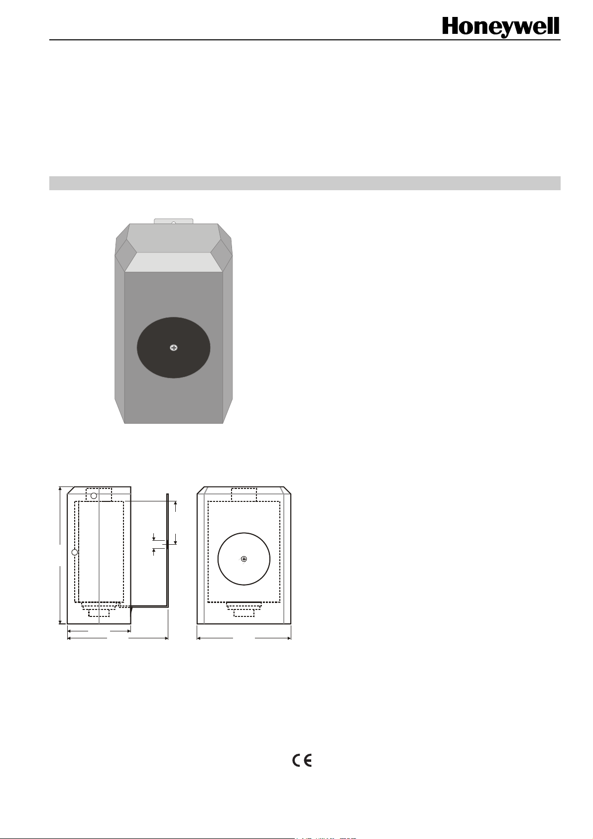
DIMENSIONS
1
SAF25
SUN COMPENSATOR - SOLAR SENSOR
PRODUCT DATA
APPLICATION
The SAF25 Sun Compensator – Solar Sensor is an active
sensor with standard output signal (0...10 V). The heating
consumption of a room depends largely on the outside
temperature. This relationship is taken into consideration by
the weather-responsive supply temperature controller when
regulating the heat supply.
In addition, the heating consumption depends on solar
radiation. On bright days, the indoors are also heated by the
sun, thereby making it possible to reduce heating and energy.
It is therefore recommended that you separate the heating
circuit of a building into north and south zones in order to take
into consideration the effect of the sun on the south side when
heating the building.
The heating supply temperature will be reduced to compensate for increasing solar radiation according to the
measurements of the SAF25.
The SAF25 contains two temperature sensors to register
solar radiation (see Fig. 1). The temperature sensor (1)
measures the ambient temperature and the solar sensor (2)
measures the radiation from the sun. The difference between
the two temperatures represents the additional heating of the
building by the sun.
TYPE
30 mm
2
95 mm
44 mm
70 mm 65 mm
® U.S. Registered Trademark EN0B-0642GE51 R0709
Copyright © 2009 Honeywell Inc. • All rights reserved
5.5 mm
Fig. 1. Dimensions (mm)
SAF25
Page 2
SAF25 – PRODUCT DATA
MOUNTING
The SAF25 should be mounted so as to measure the same
solar radiation as that of the room to be controlled.
Therefore, for sun compensation, a separate sensor has to
be installed for each control loop.
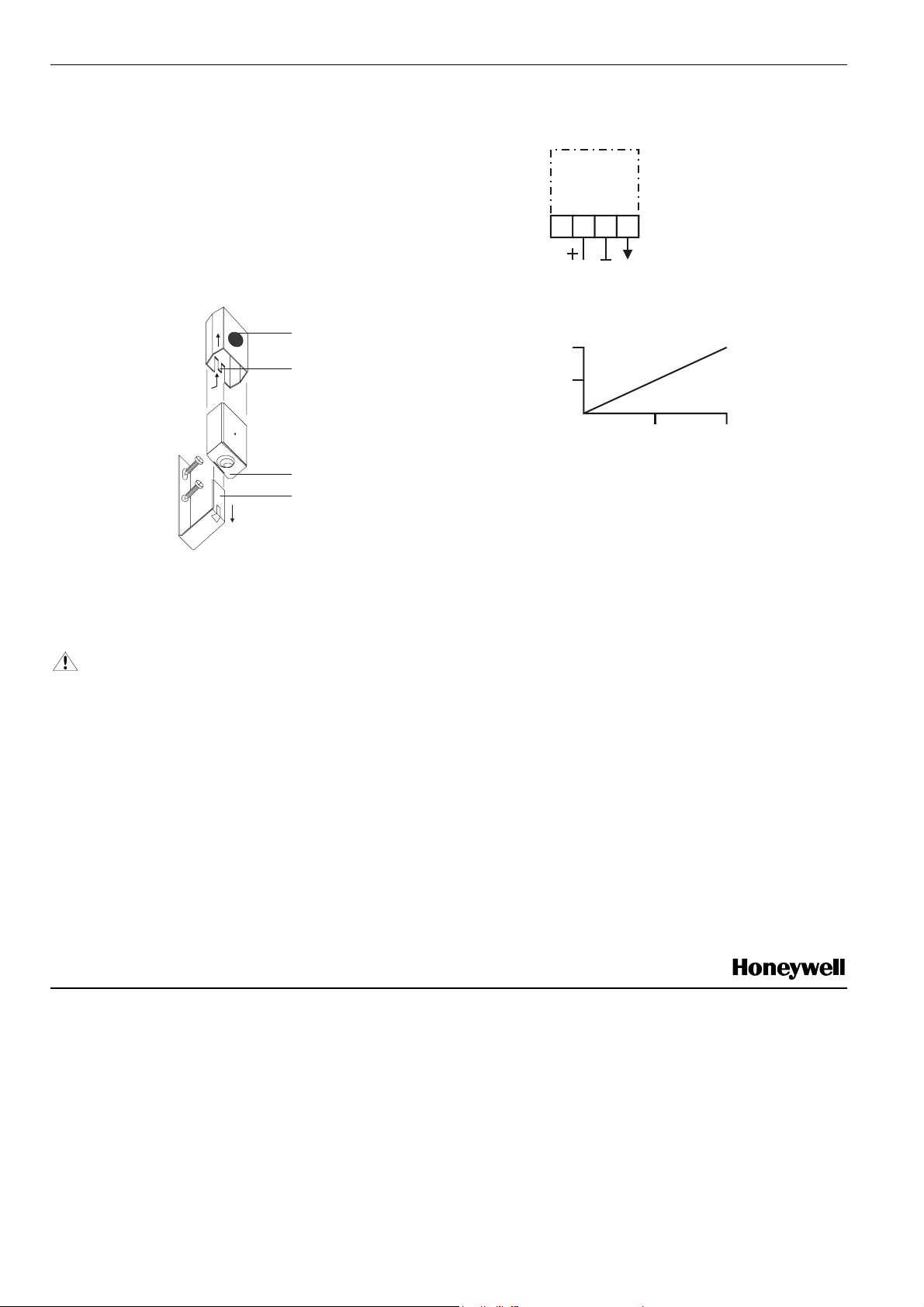
Press in the clasp (R) and pull off the top (H). Pull the clip
(B) out of the housing (G). Screw on the clip (B) and put on
the housing. To wire, unscrew the lid. Slide the top (H) over
the housing until the clasp is firmly attached.
SAF25
3
1 2
4
0...10V10V=
H
R
G
B
Fig. 2. Mounting
ELECTRICAL CONNECTION
WARNING
The sensor in the lid is connected to the circuit board
via two flexible wires. This connection must not be
severed.
[ V ]
5.0
2.5
0
250
Fig. 3. Wiring
Connect + 10 V from the controller with which the sensor is
connected to terminal 2, with the return at terminal 3.
Terminal 4 is the sensor output and is connected to the
appropriate controller input.
500
2
[W/m ]
TESTING
Both sensors can be tested by measuring the resistance:
Solar sensor on terminals 1 – 2
Temperature sensor on terminals 1 – 3
The sensors must be disconnected from the controller and
protected from the sun's rays before measuring the
resistance.
Take care when measuring, as the solar sensors may be
warm from the sun.
Manufactured for and on behalf of the Environmental and Combustion Controls Division of Honeywell Technologies Sàrl, Rolle, Z.A. La Pièce 16, Switzerland by its Authorized Representative:
Automation and Control Solutions
Honeywell GmbH
Böblinger Strasse 17
71101 Schönaich
Germany
Phone: (49) 7031 63701
Fax: (49) 7031 637493
http://ecc.emea.honeywell.com
Subject to change without notice. Printed in Germany
EN0B-0642GE51 R0709
 Loading...