

Page 1
R8182D,E,F,H,J Combination
Protectorelay™ Primary Control and
APPLICATION
The R8182 combines a Protectorelay™ primary control
and immersion type Aquastat® controller in one unit for
use in oil-fired, hydronic heating systems.
The Protectorelay™ primary control provides control of a
line voltage, intermittent ignition oil burner when used
with a C554A Cadmium Sulfide Flame Detector and a
24V thermostat.
The R8182 models provide switching as follows:
Model Switching
R8182D High limit, spst;
R8182E High limit, spst
R8182F High limit, spst
R8182H (with remote bulb) High limit, spst
R8182J (with remote bulb) High limit, spst
The auxiliary ZC and ZR terminals on the R8182D,E,H,J
provide zone control through an R845A Switching Relay.
All models are capable of zone control using zone
valves. Each additional zone requires a separate 24V
thermostat and a V8043 or V8044 Zone Valve.
The R8182D,E,F models mount directly on the boiler.
The R8182H,J models mount directly on a 4 by 4 inch
junction box and have a 5 foot (1.5 meter) armored
capillary for remote sensor location.
To order an immersion well, use form 68-0040
Fittings for Temperature Controllers
and descriptions.
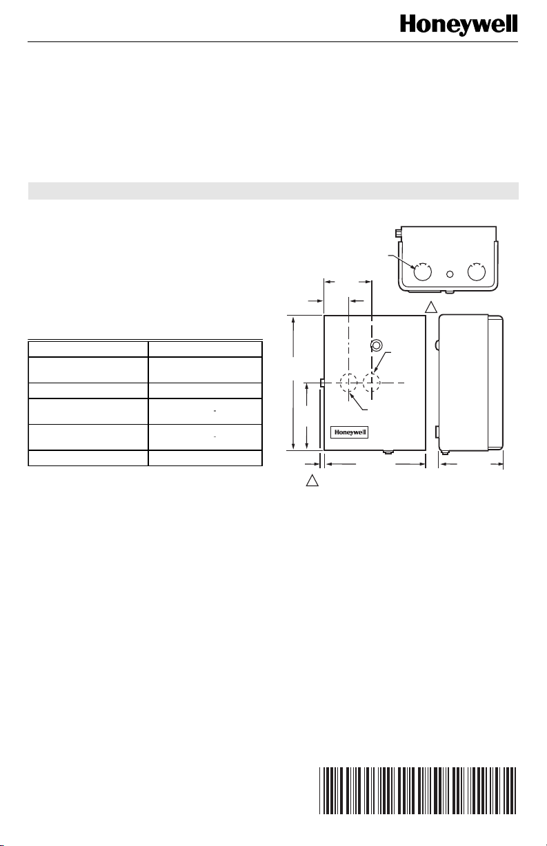
Refer to Fig. 1 through 3 for installation dimensions.
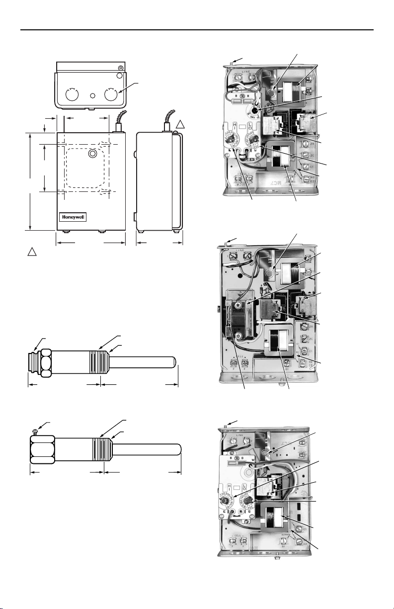
Refer to Fig. 4 through 8 for internal views of the
R8182D,E,F,G,J.
Low limit/circulator, spdt
Circulator, spst
Low limit/circulator, spdt
, for part numbers
Wells and
Aquastat
®
Controller
INSTALLATION INSTRUCTIONS
KNOCKOUTS
FOR 1/2 IN.
(13 MM)
CONDUIT (5)
2-7/16
(62)
1-5/16
(33)
7-1/8
(181)
3-9/16
(91)
3/16
(5)
1 VERTICAL MOUNT SHOWN.
Fig. 1. R8182D,E,F installation dimensions in inches
HORIZONTIAL
MOUNT ONLY
5-1/4 (133)
(millimeters).
VERTICAL
MOUNT
ONLY
1
3-1/4 (83)
M4517
Copyright © 1995 Honeywell Inc. • All Rights Reserved
X-XX UL
69-0600-1
Page 2
R8182D,E,F,H,J COMBINATION PROTECTORELAY™ PRIMARY CONTROL AND AQUASTAT® CONTROLLER
SAFETY SWITCH
RESET BUTTON
TRANSFORMER
FOR THERMOSTAT
CIRCUIT
DIFFERENTIAL
SETTING
CIRCULATOR
RELAY (1K)
BURNER MOTOR
AND IGNITION
RELAY (2K)
LOW LIMIT
SETTING
VOLTAGE BARRIER
TRANSFORMER FOR
CAD CELL CIRCUIT
M4525
1/2 (13)
7-1/8
(181)
7/8
(22)
3-7/16
(87)
3-3/8 (86)
KNOCKOUTS
FOR 1/2 IN. (13 MM)
CONDUIT (5)
GROUNDING SCREW
1
HIGH LIMIT
SETTING
Fig. 4. Internal view of R8182D.
SAFETY SWITCH
1 SIDE MOUNTED HINGE SHOWN.
5-1/4 (133)
Fig. 2. R8182H,J installation dimensions in inches
(millimeters).
3-7/16 (87)
M4518
GROUNDING SCREW
RESET BUTTON
TRANSFORMER
FOR THERMOSTAT
CIRCUIT
AQUASTAT SWITCH
CIRCULATOR
RELAY (1K)
R8182D,E,F
CONTROL MOUNT
INSULATION LENGTH
1-1/2 OR 3 IN.
(38 OR 76 MM)
R8182H,J
SETSCREW
FITS BOILER TAPPED HOLE
1/2 OR 3/4 NPT
INSERTION LENGTH
3-3/8 IN. (86 MM)
FITS BOILER TAPPED HOLE
1/2 OR 3/4 NPT
INSULATION LENGTH
1-1/2 IN. (38 MM)
Fig. 3. Immersion well dimensions in inches
(millimeters).
INSERTION LENGTH
3-3/8 IN. (86 MM)
69-0600—1
M4530
BURNER MOTOR
AND IGNITION
RELAY (2K)
VOLTAGE BARRIER
HIGH LIMIT
SETTING
TRANSFORMER FOR
CAD CELL CIRCUIT
M4532
Fig. 5. Internal view of R8182E.
GROUNDING SCREW
SAFETY SWITCH
RESET BUTTON
HIGH LIMIT
SETTING
BURNER MOTOR
AND IGNITION
RELAY (2K)
LOW LIMIT
SETTING
TRANSFORMER FOR
CAD CELL CIRCUIT
VOLTAGE BARRIER
M4515
Fig. 6. Internal view of R8182F.
2
Page 3
R8182D,E,F,H,J COMBINATION PROTECTORELAY™ PRIMARY CONTROL AND AQUASTAT® CONTROLLER
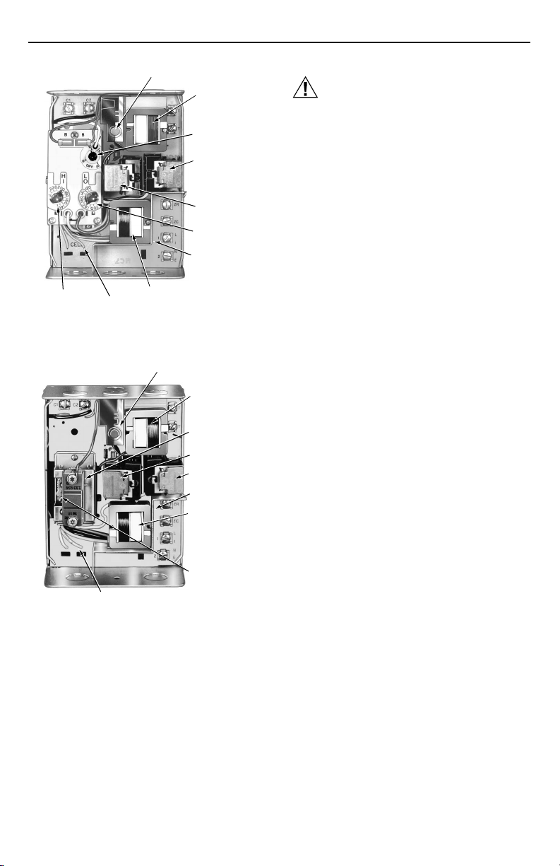
SAFETY SWITCH
RESET BUTTON
HIGH LIMIT
SETTING
CAD CELL
LEADS (YELLOW)
TRANSFORMER FOR
CAD CELL CIRCUIT
Fig. 7. Internal view of R8182H.
CAD CELL LEADS (YELLOW)
Fig. 8. Internal view of R8182J.
INSTALLATION
When Installing this Product…
Read these instructions carefully. Failure to follow
them could damage the product or cause a
hazardous condition.
Check the ratings given in these instructions and
on the product to be sure the product is suitable
for your application.
Be sure the installer is a trained, experienced
service technician.
After completing installation, use these
instructions to check product operation.
VOLTAGE BARRIER
SAFETY SWITCH
RESET BUTTON
TRANSFORMER
FOR THERMOSTAT
CIRCUIT
AQUASTAT SWITCH
2K RELAY
1K RELAY
VOLTAGE BARRIER
TRANSFORMER
FOR CAD CELL
CIRCUIT
HIGH LIMIT
SETTING
TRANSFORMER
FOR THERMOSTAT
CIRCUIT
DIFFERENTIAL
SETTING
CIRCULATOR
RELAY (1K)
BURNER MOTOR
AND IGNITION
RELAY (2K)
LOW LIMIT
SETTING
M4524
M4531
CAUTION
1. Disconnect the power supply before
beginning installation to prevent electrical
shock or equipment damage.
2. Be sure that the combustion chamber is
clear of oil or oil vapor before starting burner.
3. Be sure that the ambient temperature at the
element does not exceed 250°F (121°C).
IMPORTANT
Be sure that the sensing bulb fits snugly inside
the immersion well and that the sensing bulb
rests against the bottom of the immersion well.
Refer to Fig. 3.
Mounting the R8182
Disconnect power supply.
Drain all water from boiler.
Most boilers are equipped with a tapping that
allows horizontal mounting of immersion well
where average temperature boiler water circulates
freely. If no tapping is provided, prepare one.
Install immersion well or compression fitting
(ordered separately) by threading immersion well
into tapped hole.
For R8182D,E,F models:
a. Loosen immersion well clamp screw on side
of R8182 case.
b. Insert bulb into immersion well until it bottoms.
c. If necessary, bend capillary tube to hold
bulb against bottom of immersion well.
NOTE: Do not make sharp bends in the tubing.
A sharp bend can break the tubing and
cause a loss of fill. In models with an
adjustable tubing length, pull the extra
tubing out of the controller case.
d. Fit controller case onto immersion well so
that immersion well clamp slides over flange
of immersion well.
e. Securely tighten immersion well clamp screw.
For R8182H,J models:
a. Loosen the screw holding the hinged
backplate to the controller case and swing
the backplate away from the controller case.
b. Screw the backplate to a 4 by 4 inch
junction box.
c. Insert bulb into immersion well until it bottoms.
d. If necessary, bend capillary tube to hold
bulb against bottom of immersion well.
NOTE: Do not make sharp bends in the tubing.
A sharp bend can break the tubing and
cause a loss of fill. In models with an
adjustable tubing length, pull the extra
tubing out of the controller case.
e. Tighten immersion well screw over brass
collar.
f. After wiring, swing the control against the
backplate and refasten the screw.
Refill the boiler and check for water leakage.
3
69-0600—1
Page 4

R8182D,E,F,H,J COMBINATION PROTECTORELAY™ PRIMARY CONTROL AND AQUASTAT® CONTROLLER
Wiring
IMPORTANT
Use Underwriters Laboratories Inc. listed
connectors when making external circuit
connections to the orange and white line voltage
burner and ignition leadwires of the R8182H,J.
CAUTION
Disconnect power supply before wiring to
prevent electrical shock or equipment damage.
All wiring must comply with local codes, regulations,
and ordinances.
IMPORTANT
Terminals on the R8182 are approved for
copper wire only.
Follow the wiring instructions furnished by the appliance
manufacturer, if available, or refer to Fig. 9 through 15. For
wiring multiple zoning systems, refer to Fig. 14 and 15.
The R8182 is equipped with special wiring terminals.
Wires can be wrapped around the terminal screw or
inserted from the side.
Method 1
Strip 7/16 inches of insulation
from the wire end.
Wrap wire 3/4 of distance
around screw as shown in
Method 1.
Use a standard, flat-headed
screwdriver to tighten screw
until wire is snugly in contact
with screw and contact plate.
Tighten the screw an additional one half turn.
Method 2
Strip 5/16 inches of insulation from
the wire end.
Insert wire beneath screw as
shown in method 2.
Using a standard, flat-
headed screwdriver, tighten
screw until wire is snuggly in
contact with screw and contact plate.
Tighten screw an additional one half turn.
NOTE: Do not use a push-type ratchet screwdriver.
OPERATION
R8182D
A call for heat by the thermostat pulls in relays 1K and
2K to turn on the burner. Safety switch starts to heat. If
burner ignites within safety switch timing, cad cell sees
flame and safety switch heater circuit is bypassed.
Burner operates until call for heat is satisfied. Circulator
operates when relay 1K pulls in
the Aquastat® controller.
When R to B (low-limit) is made by a drop in water
temperature, it acts as a call for heat, pulling in relay 2K
only
if R to W is made in
M8843
M4516
1
L1
L2
(HOT)
4
1
G
1K2
BLACK
1K
T T F F
24 VOLT
THERMOSTAT
120 VAC POWER SUPPLY. PROVIDE DISCONNECT MEANS AND
1
OVERLOAD PROTECTION AS REQUIRED.
WHEN THE BLACK AND WHITE WIRES ON THE TRADELINE® R8182D
2
AQUASTAT® CONTROLLER ASSEMBLY ARE DISCONNECTED FROM
THE CIRCULATOR SWITCH AND ARE INTERCONNECTED, LOW LIMIT
AND CIRCULATOR CONTROL ARE BYPASSED. CIRCULATOR
OPERATES WITHY THEROMSTAT ONLY.
3
TO REPLACE R8182C,F, REMOVE BLUE WIRE AND INSULATE END.
DISCONNECT THE THE OTHER BLUE WIRE AT 4 AND WIRE TO
AT 3. WHEN CIRCULATOR IS CONNECTED BETWEEN ZC AND C2,
LOW LIMIT FUNCTION IS REMOVED AND CIRCULATOR OPERATES
WITH CIRCULATOR CONTROL (R TO W) ONLY.
4
CONTROL CASE MUST BE CONNECTED TO EARTH GROUND.
USE GROUNDING SCREW PROVIDED.
2
4
CIRCULATOR
R8182D
3
BLUE
ZR
BLUE
B
LOW
LIMIT
R
C1
W
BILATERAL
SWITCH
WHITE
SAFETY
SWITCH
HEATER
TRIAC
R2
C554A
3
B
2
2K2
HIGH LIMIT
ZC
1K1
2K1
B2
C2
C1
S.SW
CONTACTS
2K
TO OIL
B1R
BURNER
AND
IGNITION
TO WATER
CIRCULATOR
R1
B
M4519
Fig. 9. R8182D internal schematic and wiring diagram.
to turn on the burner. Circulator cannot operate. See
Fig. 4, 9, 14, 15, and 17.
R8182E
Burner and circulator operate whenever thermostat calls
for heat. Relay 2K pulls in. When cadmium sulfide cell
sees flame, the safety switch heater circuit is bypassed.
2K is held in through 2K1. If temperature rises to high
limit setpoint, R to B breaks, shutting off burner.
Circulator continues operation under direction of
thermostat. See Fig. 5, 10, 15, and 16.
R8182F
A thermostat call for heat pulls in relay 2K to turn on the
burner. When cadmium sulfide cell sees flame, safety
switch heater circuit is bypassed. Circulator is independent
of thermostat circuit, being controlled only by Aquastat®
controller switch. Refer to Figs. 6, 11, 15, and 18.
69-0600—1
4
Page 5

R8182D,E,F,H,J COMBINATION PROTECTORELAY™ PRIMARY CONTROL AND AQUASTAT® CONTROLLER
1
L1
L2
(HOT)
2
1
2
G
1K2
ZR
ZC
1K
T T F F
24 VOLT
THERMOSTAT
120 VAC POWER SUPPLY. PROVIDE DISCONNECT MEANS AND
1
OVERLOAD PROTECTION AS REQUIRED.
CONTROL CASE MUST BE CONNECTED TO EARTH GROUND.
2
USE GROUNDING SCREW PROVIDED.
Fig. 10. R8182E internal schematic and wiring
C1
1K1
SAFETY
SWITCH
HEATER
TRIAC
BILATERAL
SWITCH
R2
C554A
diagram.
HIGH LIMIT
B
2K1
R8182E
2K2
B2
C2
C1
S.SW
CONTACTS
2K
R1
M4527
B1R
TO OIL
BURNER
AND
IGNITION
TO WATER
CIRCULATOR
R8182H
A call for heat by the thermostat pulls in relays 1K and
2K to turn on the burner. Safety switch starts to heat. If
burner ignites within safety switch timing, cadmium
sulfide cell sees flame and safety switch heater circuit is
bypassed. Burner shuts off when call for heat is
satisfied. Circulator operates when relay 1K pulls in
if R to W in the Aquastat® controller is made.
When R to B (low-limit) is made by a drop in water
temperature, it acts as a call for heat, pulling in relay 2K
to turn on the burner. Circulator cannot operate. See
Fig. 7, 12, 15, and 17.
only
R8182J
Burner and circulator operate whenever the thermostat
calls for heat. Relay 2K pulls in. When cadmium sulfide
cell sees flame, the safety switch heater circuit is
bypassed. 2K is held in through 2K1. If temperature
rises to high-limit setpoint, R to B breaks, shutting off
burner. Circulator continues operation under direction of
thermostat. See Fig. 8, 13, 15, and 16.
Multizone Control
In all multizone applications, a call for heat in any zone
energizes the safety switch circuit and relay 2K pulls in.
If burner ignites within safety switch timing, cad cell
sees flame and safety switch heater is bypassed.
1
L1
L2
(HOT)
TRIAC
R8182F
W
C1
TO WATER
C2
B2
CIRCULATOR
TO
BURNER
AND
B1
IGNITION
M4528
2
1
2
G
JUMPER
R
B
SAFETY
SWITCH
CONTACTS
T
2K
24 VOLT
THERMOSTAT
T
R1
120 VAC POWER SUPPLY. PROVIDE DISCONNECT MEANS AND
1
OVERLOAD PROTECTION AS REQUIRED.
CONTROL CASE MUST BE CONNECTED TO EARTH GROUND.
2
USE GROUNDING SCREW PROVIDED.
Fig. 11. R8182F internal schematic and wiring
In all multizone applications with R8182D and H, the
low- limit controller in the Aquastat® acts independently
to turn on the main burner on a drop in water
temperature. When R to B (low-limit) is made, relay 2K
pulls in to turn on the main burner, the same as for
single-zone applications.
R
HIGH
CIRCULATOR
LIMIT
CONTROL
2K2
2K1
SAFETY
SWITCH
HEATER
BILATERAL
SWITCH
R2 C1
F F
C554A
diagram.
Zone Circulator Control with R8182D,H
The relay for each zone is connected to the Aquastat®
controller through terminals ZC and ZR. The R845
Relay and thermostat for each zone can energize the
zone circulator through ZC
Aquastat® controller is made. If R to B (high-limit) is
made, the zone thermostat energizes the burner
through ZR.
only
if R to W in the
Zone Circulator Control with R8182E,J
The relay for each zone is connected to the Aquastat®
controller through terminals ZC and ZR. The R845A
Relay and thermostat in each zone can energize the
zone circulator through ZC on a call for heat. If R to B
(high-limit) is made, the zone thermostat energizes the
burner through ZR.
Zone Valve Control with R8182
The valve for each zone is connected to the Aquastat®
controller by wiring end switches on the zone valve to T-T
on the R8182. On a call for heat from any zone, the
R8182 operates the same as in single-zone applications.
5
69-0600—1
Page 6

R8182D,E,F,H,J COMBINATION PROTECTORELAY™ PRIMARY CONTROL AND AQUASTAT® CONTROLLER
1
L1
L2
(HOT)
1
2
ZR
1K2
B
LOW
LIMIT
R
CIRCULATOR
1K
T T
24 VOLT
THERMOSTAT
120 VAC POWER SUPPLY. PROVIDE DISCONNECT MEANS AND
1
OVERLOAD PROTECTION AS REQUIRED.
C1
YELLOW
Fig. 12. R8182H internal schematic and wiring
W
SAFETY
SWITCH
HEATER
TRIAC
BILATERAL
SWITCH
R2
C554A
diagram.
HIGH LIMIT
B
ZC
2K2
STARTUP AND CHECKOUT
WARNING
CAN CAUSE PROPERTY DAMAGE,
SEVERE INJURY OR DEATH.
This product is intended for use only in systems
with a pressure relief valve.
Because heating systems differ, the correct temperature
setting for one system may not be correct for another.
Follow the boiler manufacturer recommendations for
proper selection of settings.
High-Limit Setting—All Models
The high-limit opens and turns off the burner when the
water temperature reaches the setpoint. The high-limit
automatically resets after the water temperature drops
past the setpoint and through the 10°F (6°C) (15°F [8°C]
with R8182E,J) differential.
Set the indicator at desired shutoff temperature.
Low-Limit/Circulator Setting—D and H Models
R
1K1
S.SW
CONTACTS
2K
2K1
ORANGE
WHITE
R1
YELLOW
R8182H
C1
C2
M4520
TO OIL
BURNER
AND
IGNITION
TO WATER
CIRCULATOR
At any differential setting greater than 10°F (6°C), the RB make temperature and R-W break temperature
remain the same—control setting minus 10°F (6°C). The
R-B break and R-W make temperatures are the setpoint
temperature plus the difference between the differential
setting and 10°F (6°C).
EXAMPLE: Setpoint of 140°F (60°C), differential set at
25°F (14°C). On a temperature rise, R-B breaks and RW makes at 155°F (68°C). On a temperature fall, R-B
makes and R-W breaks at 130°F (54°C).
Set low-limit indicator at the minimum temperature
recommended for domestic hot water supply. The
setting
setting to prevent one switch from locking out the other.
Set differential the desired number of degrees.
Circulator Setting—F MODELS (Fig. 18)
Set circulator indicator at the minimum water
temperature recommended for hydronic heating
comfort. Circulator breaks 10°F (6°C) below setpoint.
Startup
(Fig. 17)
On a temperature rise, with the adjustable differential at
the minimum setting of 10°F (6°C), the burner circuit (RB) breaks and the circulator circuit (R-W) makes at the
low-limit setpoint. See Fig. 17. On a temperature drop of
10°F (6°C) below the setpoint, the R-B circuit makes
and the R-W circuit breaks.
1
L1
L2
(HOT)
1
2
HIGH LIMIT
ZR
B
1K2
ZC
1K
C1
T T F F
YELLOW
24 VOLT
THERMOSTAT
120 VAC POWER SUPPLY. PROVIDE DISCONNECT MEANS
1
AND OVERLOAD PROTECTION AS REQUIRED.
Fig. 13. R8182J internal schematic and wiring
must
be at least 20°F (11°C) below high-limit
R
SAFETY
SWITCH
HEATER
TRIAC
BILATERAL
SWITCH
R2
C554A
diagram.
R8182J
C1
C2
YELLOW
TO OIL
BURNER
AND
IGNITION
TO WATER
CIRCULATOR
R1
M4529
ORANGE
2K2
WHITE
1K1
S.SW
CONTACTS
2K1
2K
CAUTION
Be sure combustion chamber is free of oil or vapor.
69-0600—1
6
Page 7

R8182D,E,F,H,J COMBINATION PROTECTORELAY™ PRIMARY CONTROL AND AQUASTAT® CONTROLLER
1
L1
L2
(HOT)
6
ZONE 2
THERMOSTAT
3
1
2
3
4
5
6
R845A
SWITCHING
RELAY ZONE 2
1K
2
ZONE 2
CIRCULATOR
1K1
5 3
6 4
1K2
TO ADDITIONAL
ZONES 3, 4, ETC.
T
T
1
120 VAC POWER SUPPLY. PROVIDE DISCONNECT MEANS
AND OVERLOAD PROTECTION AS REQUIRED.
THERMOSTAT HEAT ANTICIPATOR SETTING,
0.2 AMP FOR R8182D.
THERMOSTAT HEAT ANTICIPATOR SETTING,
0.4 AMP FOR R845A.
CONTROL CASE MUST BE CONNECTED TO EARTH GROUND.
USE GROUNDING SCREW PROVIDED.
R8182E,H,J CONNECTIONS FROM ZC AND ZR ARE IDENTICAL
FOR MULTIPLE CIRULATOR ZONING APPLICAITON.
EACH ADDITIONAL ZONE REQUIRES A SEPARATE, FIELD-ADDED
24V THERMOSTAT AND R845 RELAY.
Fig. 14. R8182D and R845A in a typical multiple circulator zoning application.
1. Push red reset button and release.
2. Open hand valve on oil supply line.
3. Set thermostat to call for heat.
4. Close line switch; burner will start.
5. Under normal conditions, burner operates until
thermostat is satisfied or line switch is opened.
Make certain the system operates as described in the
OPERATION section. Use the following procedure to
verify that the Protectorelay™ control is controlling
properly.
Flame Failure Check
Shut off oil supply hand valve while burner is on. After
45 seconds, the safety switch locks out, the motor
stops, and the oil valve closes. Allow five minutes for
burner to cool, then manually reset safety switch.
Ignition Failure Check
Test by closing oil supply while burner is off. Run
through starting procedure but do not open the oil
supply line hand valve. Safety switch locks out as for
flame failure. Then turn oil back on, and reset safety
switch.
Power Failure Check
Turn off power supply while burner is on. When burner
goes out, restore power and burner will reset.
R8182D
4
1
2
G
1K2
1K
T T F F
24 VOLT
THERMOSTAT
NOTE: If operation is not as described, see cover
BLUE
ZR
B
LOW
LIMIT
R
CIRCULATOR
C1
2
insert for additional information and check
wiring.
W
SAFETY
SWITCH
HEATER
TRIAC
BILATERAL
SWITCH
R2
C554A
HIGH LIMIT
B
ZC
5
2K2
B2
C2
1K1
S.SW
CONTACTS
2K
2K1
B1R
C1
R1
Aquastat® Replacement
The Aquastat® controller section of the Protectorelay™
control is field replaceable. When ordering a
replacement assembly, specify the complete model
number of the R8182.
To Replace the Aquastat® Limit:
1. Disconnect power supply.
2.
Note the position of the connecting wires
3. Remove fastening screws and wires.
4. Remove Aquastat controller and install new
assembly.
TO OIL
BURNER
AND
IGNITION
TO WATER
CIRCULATOR
M4521
.
7
69-0600—1
Page 8

R8182D,E,F,H,J COMBINATION PROTECTORELAY™ PRIMARY CONTROL AND AQUASTAT® CONTROLLER
CIRCULATOR
SETTING
HIGH LIMIT
SETTING
R-B BREAKS ON
TEMPERATURE RISE.
BURNER TURNS OFF.
R-B MAKES ON
TEMPERATURE FALL.
BURNER OPERATES
ON CALL FOR HEAT.
R-B BREAKS ON
TEMPERATURE FALL.
CIRCULATOR TURNS OFF.
R-W MAKES ON
TEMPERATURE RISE.
CIRCULATOR TURNS ON.
110°F (43°C)
240°F (116°C)
M1509
10°F (6°C)
DIFFERENTIAL
10°F (6°C)
DIFFERENTIAL
24 VOLT
THERMOSTAT
1
2
3
4
5
HIGH LIMIT
SETTING
24 VOLT
THERMOSTAT
YELLOW
YELLOW
5 5 5
RED
RED
POWER SUPPLY. PROVIDE DISCONNECT MEANS AND OVERLOAD
PROTECTION AS REQUIRED.
R8182H AND J HAVE WHITE AND ORANGE LEADWIRES FOR OIL
BURNER AND IGNITION CONNECTIONS.
RED LEADWIRES PROVIDED ONLY ON MODLES WITH END SWITCH.
CHOOSE AT72, AT87, OR AT88 TRANSFORMER TO MATCH
MAXIMUM SYSTEM LOAD.
USE V8043 OR V8044 ZONE VALVES WITH AUXILIARY END
SWITCH ONLY.
Fig. 15. R8182D,E,F,H, and J in typical zoning
application using zone valves.
YELLOW
YELLOW
RED
RED
240°F (116°C)
15°F (8°C)
DIFFERENTIAL
24 VOLT
THERMOSTAT
YELLOW
YELLOW
RED
333
RED
4
L1
(HOT)
L2
L1 L2
TTB1
B2
C2
C1
CIRCULATOR
R-B BREAKS ON
TEMPERATURE RISE.
BURNER TURNS OFF.
CIRCULATOR OPERATES
ON A CALL FOR HEAT.
R-B MAKES ON
TEMPERATURE FALL.
BURNER AND
CIRCULATOR OPERATE
ON A CALL FOR HEAT.
1
2
M4522
TO OIL
BURNER
AND
IGNITION
240°F (116°C)
HIGH LIMIT
SETTING
LOW LIMIT
AND
CIRCULATOR
SETTING
1
WHEN WATER REACHES PROPER TEMPERATURE, THE BURNER
SHUTS OFF OR THE CIRCULATOR PUMP STARTS (WHEN CALLING
FOR HEAT).
10°F (6°C)
DIFFERENTIAL
25°F (14°C)
DIFFERENTIAL
10°F (6°C)
DIFFERENTIAL
110°F (43°C)
SWITCH BREAKS ON
TEMPERATURE RISE.
BURNER TURNS OFF.
CIRCULATOR OPERATES
ON A CALL FOR HEAT.
SWITCH MAKES ON
TEMPERATURE FALL.
BURNER OPERATES ON A
CALL FOR HEAT.
SWITCH MAKES R-W
AND BREAKS R-B ON
TEMPERATURE RISE.
SWITCH MAKES R-W
AND BREAKS R-B ON
TEMPERATURE RISE.
SWITCH MAKES R-B AND
BREAKS R-W ON
TEMPERATURE FALL.
BURNER IS ON TO
MAINTAIN MINIMUM
WATER TEMPERATURE.
CIRCULATOR IS OFF.
Fig. 17. R8182D,H Aquastat® limit switching.
1
M1523
180°F (82°C)
Fig. 16. R8182E,J Aquastat® limit switching.
Automation and Control Solutions
Honeywell International Inc.
1985 Douglas Drive North
Golden Valley, MN 55422
69-0600—1
J.H. Rev. 5-95
M1510
Fig. 18. R8182F Aquastat® limit switching.
Honeywell Limited-Honeywell Limitée
35 Dynamic Drive
Scarborough, Ontario M1V 4Z9
8
 Loading...