

Page 1
™
SL AT E
Sub-Base Module
R8001S9001
INSTALLATION INSTRUCTIONS
Page 2
Scan for more information
Page 3

Application
SLATE™ brings configurable safety and programmable logic
together into one single platform. The platform can easily be
customized for almost any requirement or application–offering
virtually limitless development opportunities with far less
complexity.
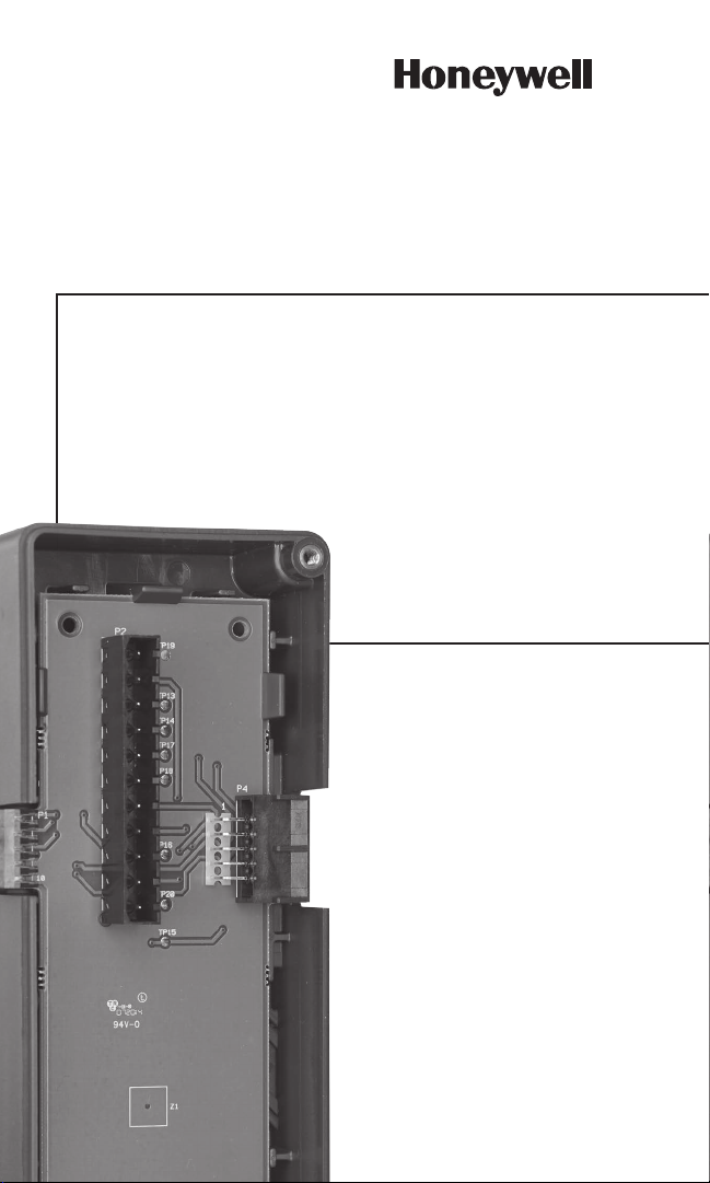
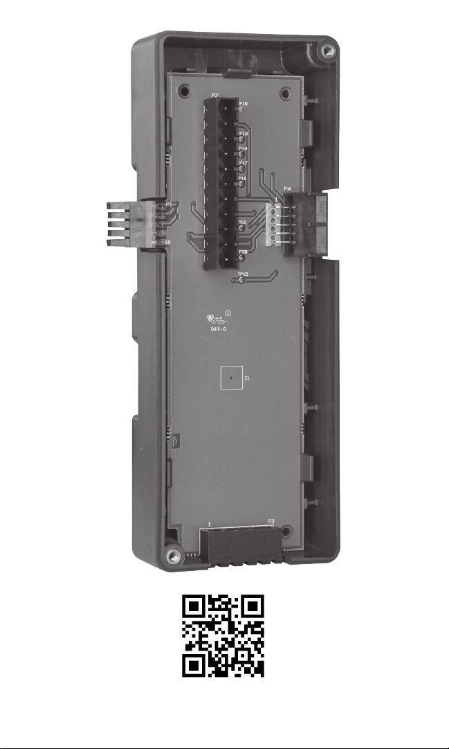
The R8001S9001 SLATE Sub-Base Module provides the ability
for the SLATE system to be mounted via DIN Rail in a panel. All
SLATE modules need this sub-base except for the SLATE Base
Module.
Features
• Quick-mount to standard DIN-Rail
• Locking mechanism
• Provides bus connectivity to all modules
• Connections for remote mounted flame amplifiers (remote bus)
and remote pushbutton reset
Specifications
Electrical Ratings:
Voltage and Frequency (from the Base): 18 VDC (± 1 VDC)
Maximum Total Connected Load: 2.5A
Terminal Ratings: See Table 1
Terminal Description Rating
1 18 V Power 2.5 A max including
modules
2 18 V Ground ---
3 Remote Reset
(Burner Control and
Limit modules only)
SLATE™ Sub-Base Module 3
R8001S9001
Connect to Terminal 2 (18
V Ground) via external
pushbutton
Page 4

Terminal Description Rating
4 B (Remote Bus
RS485)
5 A (Remote Bus
RS485)
Table 1. Terminal Ratings.
Used for Remote mounted ame ampliers
Used for Remote mounted ame ampliers
Environmental Ratings
Ambient Temperature:
Operating: -20°F to +150°F (-29°C to +66°C).
Shipping: -40°F to +150°F (-40°C to +66°C)
Humidity: 95% continuous, noncondensing.
Vibration: 0.5G environment
Dimensions: See Fig. 1.
Weight: 5 oz (136 g)
Approvals
Underwriters Laboratories Inc. Listed, File: MP286
IRI acceptable.
Federal Communications Commission: Part 15, Class A
Emissions.
Mounting
DIN Rail (See Fig. 3)
Required Components
R8001A1001 SLATE Base Module
Any other SLATE modules
Optional 5-position terminal block for remote flame amplifier or
remote reset button connections (Phoenix Contact p/n 1754504
or equivalent). See Fig. 2.
4 32-00025—01
Page 5

Fig. 1.
Dimensions in in. (mm).
2-21/32 (67)
3-13/32 (86)
7-3/32
(180)
1-5/32
(29)
M35384
SLATE™ Sub-Base Module 5
R8001S9001
Page 6
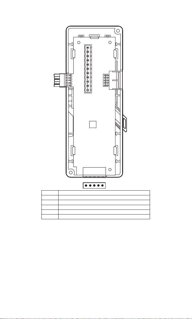
4 5
3
2
1
TERMINAL
Fig. 2.
Sub-base module wiring terminals.
18V POWER
1
2
18V GROUND
3
REMOTE RESET (BURNER CONTROL AN D LIMIT MODULES ONLY)
B (REMOTE BUS RS485)
4
A (REMOTE BUS RS485)
5
DESCRIPTION
M35430
6 32-00025—01
Page 7

Installation
WARNING
Fire or Explosion Hazard Can cause severe injury,
death, or property damage.
Verification of safety requirements must be performed
each time a control is installed on a burner to prevent
possible hazardous burner operation.
When Installing This Product
1. Read these instructions carefully. Failure to follow them could
damage the product or cause a hazardous condition.
2. Check the ratings given in the instructions and on the product
to make sure the product is suitable for your application.
Mounting
1. The sub-base module can be mounted on type C 20 DIN rail.
2. Mount the sub-base module first. The sub-base has locking
mechanisms on both sides of the module. Pull to unlock
position. See Fig. 3.
SLATE™ Sub-Base Module 7
R8001S9001
Page 8

Fig. 3.
M35378
UNLOCKED FROM DIN RAIL
LOCKED ONTO DIN RAIL
Sub-base locking mechanisms.
3. Slide sub-base on the DIN rail and lock into place.
4. When securing subsequent sub-base modules make sure
communication ports are aligned and locked into place. See
Fig. 4.
Fig. 4.
Connecting additional sub-base modules.
8 32-00025—01
M35386
Page 9

5. After securing the sub-base module, snap the SLATE module
into place and secure the module to the sub-base using
screws (included with SLATE module).
Wiring
WARNING
Electrical Shock Hazard.
Can cause severe injury, death or equipment damage.
1. Disconnect the power supply before beginning installation to
prevent electrical shock and equipment damage. More than
one power supply disconnect can be involved.
2. Wiring must comply with all applicable codes, ordinances and
regulations. See Fig. 2.
3. Wiring must comply with NEC Class 1 (Line Voltage) wiring.
Application Recommended Wire
Size
Communication
Lines
Other terminals 18 AWG wire insulat-
Table 2. Recommended Wire Sizes and Part Numbers.
IMPORTANT
This equipment generates, uses and can radiate radio frequency
energy and, if not installed and used in accordance with these
instructions, may cause interference for radio communications.
It has been tested and found to comply with the limits of a Class
A computing device of part 15 of FCC rules, which are designed
to provide reasonable protection against such interference
SLATE™ Sub-Base Module 9
R8001S9001
22 AWG two-wire
twisted pair with
ground, or ve-wire.
ed for voltages and
temperatures for given
application.
Recommended
Part Numbers
Belden 8723
shielded cable
or equivalent.
TTW60C,
THW75C,
THHN90C
Page 10

when operated in a commercial environment. Operation of this
equipment in a residential area may cause interference; in which
case, the user, at their own expense, may be required to take
whatever measures are required to correct this interference.
1. This digital apparatus does not exceed the Class A limits for
radio noise, set out in the Radio Interfeence Regulations of
the Canadian Department of Communications.
2. Cable shield must be terminated to ground at both ends. If
shielded cable is NOT used, use three-wire twisted cable.
Recommended Grounding Practices
Use an Earth ground or a signal ground as described below.
Earth Ground (Base, Rectification Flame Amp
Module, Other Modules Optional)
1. Use to provide a connection between the base and the
control panel of the equipment. Earth ground must be capable
of conducting enough current to blow the breaker in the event
of an internal short circuit.
2. Use wide straps or brackets to provide minimum length,
maximum surface area ground conductors. If a leadwire is
required, use 14 AWG copper wire.
3. Verify that mechanically tightened joints along the ground path
are free of nonconductive coatings and protected against
corrosion on mating surfaces.
Signal ground
Note the 18 V system ground is not electrically connected
to earth ground. Follow local codes and appliance
recommendations to determine if this should be connected to
earth ground.
Recommended Routing of Leadwires
• Do not run high voltage ignition transformer wires in the same
conduit with the flame detector or data lines.
• Do not route flame detector or data lines in conduit with line
voltage circuits.
10 32-00025—01
Page 11

• Enclose flame detector leadwires without armor cable in metal
cable or conduit.
• Follow directions in flame detector instructions.
Be sure loads do not exceed the terminal ratings. Refer to the
labels or terminal ratings in Table 1.
The SLATE system must be mounted in an electrical enclosure.
When mounting in an electrical enclosure, provide adequate
clearance for servicing, installation, and removal of SLATE
modules.
Maximum Wire Length
• The maximum leadwire length is 300 feet to terminal inputs
(Control, Running/Lockout Interlock)
• For remote reset leadwires, maximum length to remote
pushbutton is 1000 feet.
• For remote bus data lines, maximum cable length depends on
the number of modules connected, the noise conditions, and
the cable used. The maximum of all interconnecting wires is
4000 feet.
SLATE™ Sub-Base Module 11
R8001S9001
Page 12

For more information and detailed instructions on the SLATE display
32-00025-01
please refer to the SLATE User Guide document located on our
website at http://combustion.honeywell.com/SLATE
Automation and Control Solutions
Honeywell International Inc.
1985 Douglas Drive North
Golden Valley, MN 55422
customer.honeywell.com
® U.S. Registered Trademark.
© 2014 Honeywell International Inc.
32-00025—01 M.S. 11-14
Printed in U.S.A.
 Loading...