

Page 1
32M-06009-06
SLATE™ Low Torque Actuator
SLATE Commercial Model
Series
FOR COMMERCIAL AND INDUSTRIAL MODELS
R8001M1050, R8001M1150, R8001M4050, R8001M4150
INSTALLATION INSTRUCTIONS
FEATURES AND BENEFITS
• Offered in two different configuration options:
— NEMA 1 rated, operating in a temperature
range of -18 to 158 °F (-28 to 70 °C) with
450 positions over a 90° span
— NEMA 4 rated, operating in a temperature
range of -40 to 158 °F (-40 to 70 °C) with
900 positions over a 90° span
• Field-reversible clockwise and counterclockwise
rotation operation.
• Internal temperature, valve status, health
diagnostics, and error codes reporting.
• Robust, heavy-duty construction, continuous
duty cycle-rated.
• Closed loop position control via Modbus RS-485
communications as an input to the SLATE Fuel
Air Ratio Module, part R8001C6001.
• Dual 1/2-in knockout conduit connections.
• 1/2-in keyed output shaft with a 1/8-in square
key.
APPLICATION
SLATE brings configurable safety and programmable
logic together into one single platform. The SLATE
program can easily be customized for almost any
application—offering virtually limitless development
opportunities with far less complexity.
• Die-cast aluminum base with high-impact
resistant, reinforced plastic cover.
• Meets UL353 Safety for Limit Controls.
• Meets UL1998 when used with R8001C6001
SLATE Fuel Air Ratio Module.
The SLATE Low Torque Actuator series includes
commercial- and industrial-grade 1/4-turn actuators
available in 50 and 150 in/lb models with highly
repeatable position accuracy designed specifically to
integrate with the SLATE system. This series is well
suited for the precise control of air and gas flow and
can operate in a wide range of temperatures and
environmental conditions.
SLATE™ Low Torque Actuator can be easily mounted
to the following valves using the mounting kits noted
below. These kits can be ordered via
www.customer.honeywell.com.
• Maxon CV Valve Series (1/2"–2")
mounting kit #50123928-001
• Honeywell V51E Valve Series (1-1/2"–2")
mounting kit #50124386-001 and mounting kit
#32003396-001
• Honeywell V51E Valve Series (2-1/2"–4")
mounting kit #50124386-001 and mounting kit
#32003396-002
• Honeywell V5197A Valve Series (3/4"–3")
mounting kit #50124386-001
APPROVALS
Underwriters
Laboratories
CE 2009/142/EC: Gas Appliance
Meets UL353 Safety for Limit
Controls.
Meets UL1998 when used with
R8001C6001 SLATE Fuel Air Ratio
Module.
Directive
(EN 12067-2:2004, EN298-2012)
Page 2
SLATE™ LOW TORQUE ACTUATOR SERIES
SPECIFICATIONS
Supply Voltage (Peak Current):
DC model: 24VDC +10/-20%
Power:
50 in/lb: 10 Watts maximum
150 in/lb: 25 Watts maximum
Rotation: Max span: 90° usable
Resolution:
Commercial: 450 positions (0.2° resolution)
Industrial: 900 positions (0.1° resolution)
Control Deadband:
Commercial: ±0.2 degrees
Industrial ±0.1 degrees
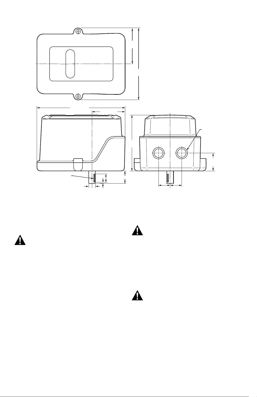
Dimensions in in (mm): 6-11/16 x 5-29/64 x 5-
29/64
(170 x 138 x 138); See Fig. 1
Weight: 3 Lbs. (1.4 Kg)
Operating Temperature:
-28 to +70 °C (-18 to +158 °F) for commercial models; -40 to +70 °C (-40 to +158 °F) for industrial
models
Storage Temperature: -40 to +80 °C (-40°F to
+176°F)
Vibration: Honeywell V2 test specification; 3 axes
tested as follows:
2-Hour Performance/Resonant Detection Sweep:
Vibration sinusoidal: 5 Hz - 30 Hz;
Amplitude: 0.012mil pk/pk75 mm
Vibration sinusoidal: 30 Hz – 300 Hz at 0.6G
Endurance: 1.1G for 2 hours at resonant frequencies
EMC: EN61000-6-1/2/3 (See Safety and Agency
Approval Requirements), FCC Part 15, Level A
EN55022, Level A
Enclosure:
NEMA1 (commercial models)
NEMA 4 (industrial models)
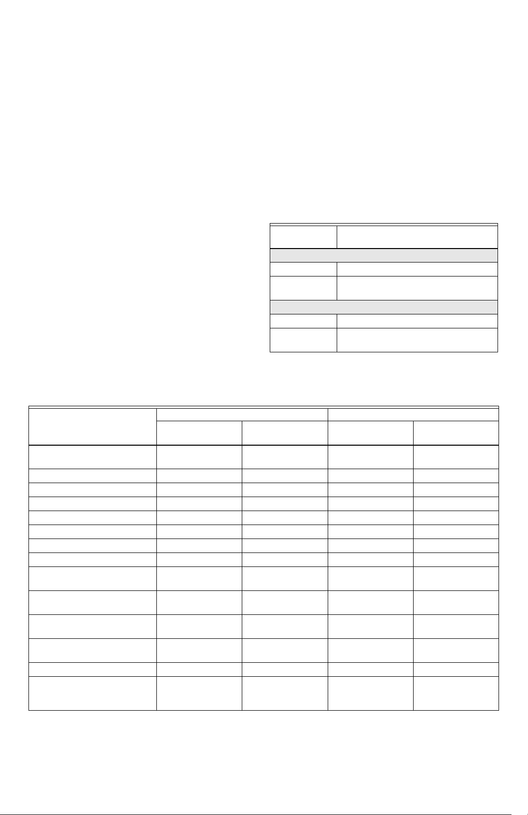
Models:
Model
Number Description
Commercial
R8001M1050 50 in/lb Actuator NEMA 1 Enclosure
R8001M1150 150 in/lb Actuator NEMA 1
Enclosure
Industrial
R8001M4050 50 in/lb Actuator NEMA 4 Enclosure
R8001M4150 150 in/lb Actuator NEMA 4
Enclosure
Relative Humidity:
0 to 99% non condensing (for commercial models)
Table 1. Model Specifications.
Commercial Model Industrial Model
50 in-lb
Actuator Options/Specs
Communication RS-485 non-
Fault Annunciation Generic Alarm Generic Alarm Yes Yes
Enhanced Data Logging None None Yes Yes
Resolution .2 Degree .2 Degree .1 Degree .1 Degree
Repeatability .2 Degree .2 Degree .1 Degree .1 Degree
Duty Cycle (Act Availability) 100% 100% 100% 100%
Opening Span 90 Degrees 90 Degrees 90 Degrees 90 Degrees
90 Degree Travel Time 30 sec 30 sec 15 sec max 15 sec max
Minimum Operating
Tem per ature
Maximum Operating
Tem per ature
Temp Sensor Yes; Alarm Only Yes; Alarm Only Yes; Alarm and
Output 1/2-in Keyed
Keyed Connection 1/8-in Square Key 1/8-in Square Key 1/8-in Square Key 1/8-in Square Key
Conduit Connections 1/2-in Conduit
R8001M1050
isolated
-28 °C (-18 °F) -28 °C (-18 °F) -40 °C (-40 °F) -40 °C (-40 °F)
70 °C (158 °F) 70 °C (158 °F) 70 °C (158 °F) 70 °C (158 °F)
Output Shaft
Knockouts (2)
(Shipped Closed)
150 in-lb
R8001M1150
RS-485 nonisolated
1/2-in Keyed
Output Shaft
1/2-in Conduit
Knockouts (2)
(Shipped Closed)
50 in-lb
R8001M4050
RS-485 Isolated RS-485 Isolated
Real Time Data
1/2-in Keyed
Output Shaft
1/2-in Conduit
Knockouts (2)
(Shipped Closed)
150 in-lb
R8001M4150
Yes; Alarm and
Real Time Data
1/2-in Keyed
Output Shaft
1/2-in Conduit
Knockouts (2)
(Shipped Closed)
32M-06009—06 2
Page 3
SLATE™ LOW TORQUE ACTUATOR SERIES
WARNING
WARNING
WARNING
M35299
(2) Ø 7/8 (22)
KNOCKOUTS
FOR 1/2”
CONDUIT
ENTRANCE
KEYWAY FOR
1/8” SQ. X 1/2” LG. KEY
6-11/16 (170)
2-47/64
(69)
5-29/64
(138)
2-33/64 (64)
Ø 1/2 (13)
3/32 (3)
5/8 (16)
61/64 (24)
5-29/64
(138)
7/8 (22)
7/8 (22)
1-11/32
(34)
Fig. 1. Dimensions in in (mm).
INSTALLATION INSTRUCTIONS
Read Carefully
Please read the operating and mounting
instructions before using the equipment.
Install the equipment in compliance with the
prevailing regulations.
Bedrijfs- en montagehandleiding voor gebruik
goed lezen! Apparaat moet volgens de
geldende voorschriften worden geïnstalleerd.
Lire les instructions de montage et de service
avant utilisation! L’appareil doit
imperativement être installé selon les
règlementations en vigueur.
Betriebs- und Montageanleitung vor Gebrauch
lesen! Gerät muß nach den geltenden
Vorschriften installiert werden.
NOTICE
Language translations for this document are available
at www.customer.honeywell.com.
Safety requirements
Safety Notice
The SLATE Actuator has been independently
evaluated by Underwriters Laboratories to
provide position feedback to the SLATE Fuel Air
Ratio Module. The safety of the overall system
is ultimately the responsibility of: 1) The
upstream safety control that commands and
monitors the SLATE Actuator, and 2) the
trained commissioning engineer that
configures the unit for system operation.
Safety Hazard
Before operating this product, check all
specifications and safety requirements to
ensure the product is suitable and safe for the
intended application. In addition, read all
installation, commissioning, and operating
instructions. The SLATE Actuator must be set
up and maintained in the field by qualified
personnel. If the equipment is used in a
manner not specified, the protection provided
by the equipment may be impaired.
3 32M-06009—06
Page 4

SLATE™ LOW TORQUE ACTUATOR SERIES
WARNING
WARNING
2X 3-1/2 (89)
M35300
1-1/8
(28)
THREADED FOR
M6 x 1 (25) x 1/2 (12)
FASTENER
O 1/4 (6) X 17/64 (7)
DEEP FOR OPTIONAL
DOWEL PIN
1-1/8
(28)
1-1/8
(28)
1 (25)
1 (25)
2X 1-3/8
(35)
2X 1-3/8
(35)
M35301
0° IF ROTATION IS SET TO CCW
90° IF ROTATION IS SET TO CW
5° SPAN
ADJUSTMENT
RANGE
(ADDITIONAL
TRAVEL)
5° SPAN
ADJUSTMENT
RANGE
(ADDITIONAL
TRAVEL)
90° IF ROTATION IS SET TO CCW
0° IF ROTATION IS SET TO CW
SHAFT KEY
INDICATES
ROTATIONAL
POSITION
Mounting
The actuator assembly may be installed in any
orientation.
Keep Free of Dust and Water
• Maintain the integrity of the enclosure by
using NEMA 4X rated dust- and water-tight
electrical connectors.
• Use cable-sealing grips and strain-relief
loops for any cord or cable.
• Plug unused conduit holes. Use internal
sealing materials on all conduit connections.
Moisture can have a harmful effect on device
internals if permitted to enter through wiring
connectors.
• Ensure that the device connection is not at a
low point of the conduit to avoid
condensation run-off into the housing;
install a drip loop if necessary.
• All cover screws should be tightened to the
specified torque. See Fig. 4.
• Cover screws should be checked periodically
to ensure adequate sealing protection.
If you are mounting the SLATE™ Low Torque Actuator
using third party valves, it is important to follow the
following assembly instructions:
1. Ensure that the SLATE™ Low Torque actuator
has sufficient torque for the valve's required
break-away torque. Also consider the line
pressure when making this calculation.
2. Turn off the fuel supply upstream from the
applicable valve.
3. Remove all external hardware from the third
party valve.
4. The SLATE actuator's shaft is ½-in. diameter
with a 1/8-in. square key. For a smaller 3/8-in.
valve shaft you must insert an adapter so that
the two shafts are concentrically aligned, ensure
that the set screws solidly contact both shafts.
5. If the bracket assembly permits, attach the
coupling to the valve and the actuator first,
ensuring exact alignment. After the coupling is
tightened, assemble and tighten the mounting
brackets. Do not tighten the mounting brackets
first.
6. Observe the actuator while it travels over its
entire range and ensure smooth operation. If
sticking/binding is observed, or if Slate reports
actuator error codes, the actuator shaft is not
properly aligned and must be re-adjusted.
Ensure the media temperature cannot exceed the
valve or actuator ratings. Use a coupling with thermal
breaks if required. If the possibility exists for radiant
heating (such as a furnace application), install a
thermal barrier.
Ensure that pipe and ductwork are free of debris that
could impair valve function.
See Fig. 2 for the locations of the mounting holes. The
mounting holes are threaded for M6 x 1 x 1/2-in
(12mm) fasteners.
Fig. 2. Mounting holes.
Note the quadrant of the keyway and rotation
direction. See Fig. 3.
Fig. 3. Actuator rotation direction.
NOTE: The SLATE Actuator ships CCW as default.
Electrical installation
Electrical Shock Hazard.
Can cause severe injury, death or equipment
damage.
Disconnect the power supply before beginning
installation to prevent electrical shock and
equipment damage. More than one power
supply disconnect can be involved.
Wiring terminals
Fig. 4 indicates each wiring terminal and Table 2
identifies each terminal’s signal type and function.
32M-06009—06 4
Page 5

Fig. 4. Wiring terminals.
WARNING
Com
(c) (b) (a)*
* AS PER THE LABEL ON
THE FUEL AIR RATIO MODULE
–
+
MODBUS
RS-485
V+ V-
24V DC
POWER
CHASSIS
ALL
SHIELDS
TO
CHASSIS
TORQUE COVER SCREWS: 16-18 IN LBS.
MINIMUM WIRE TEMPERATURE RATING: 90˚C (194˚F)
M35302
To access the field wiring compartment for power and
signal connections:
1. Remove the 2 screws and cover from the top of
the actuator housing.
2. Pass all customer-supplied wires into the enclo-
sure through the 2 conduit hubs.
SLATE™ LOW TORQUE ACTUATOR SERIES
4. In addition to a grounded conduit, the use of
shielded, twisted-pair cable is strongly recommended for DC power and signal wires. The
shield drain wires should be landed to chassis/earth on both ends of the cable, but ONLY if
a conduit is also grounded on both ends. In other
cases, earth the shields at actuator end only.
Input power
IMPORTANT
Use DC power only.
Use cable rated for the temperatures and voltages
required by the application. Use a gauge of wire to
minimize voltage loss (droop) over long cable runs,
especially at full current load. Ensure that voltage
specifications are met under all conditions.
See Table 2.
A fuse or breaker should be installed at the power
source. If the power supply is not factory-supplied, a
SELV (Safety Extra Low Voltage) rated supply with
regulated output must be provided.
Communication (Modbus over RS-485)
Use appropriate communication cable. A network will
consist of a customer’s Modbus master (with
termination) and one or more actuator slaves. See
SLATE documentation for wiring specifics.
Equipment Damage
To ensure physical protection as well as
electromagnetic immunity, the use of flexible,
sunlight-resistant, jacketed, metallic, watertight conduit is required. The conduit should be
connected to earth ground on both ends.
3. One or both conduit holes may be used when
wiring an actuator.
NOTE: On commercial models only:
Do not wire the non-isolated common
terminal to the Slate system; leave it
unconnected. Instead, wire the 24V- of the
actuator supply to Pin 2 of the Slate
Sub-Base. If all actuators share the same
supply, only one connection is needed.
Network layouts should be arranged so that
branch/homerun length does not exceed 300 feet for
commercial actuators, or 2000 feet for industrial
actuators.
5 32M-06009—06
Page 6

SLATE™ LOW TORQUE ACTUATOR SERIES
Table 2. Wiring Terminal Identification.
Type Terminal Description Wiring
PE (Protective Earth) Chassis
ground screw
Chassis connection for mains
power and shield/drain wires
Follow local codes for safety earth
installation. See Electrical installation
section for shield drain installation
instructions.
DC power terminals 24V+ 24VDC positive terminal Shielded twisted pair cable is
24V- 24VDC negative terminal
recommended. A replaceable 2A fuse
is provided on all actuators. Use a
slow blow fuse if additional external
fusing is desired. Required gauges
are:
Up to 80 ft: 24 AWG
Up to 120 ft: 22 AWG
Up to 500 ft: 16 AWG
Up to 800 ft: 14 AWG
Up to 1200 ft: 12 AWG
Low voltage
communication
(Modbus over RS-485)
Industrial models only:
R8001M4050,
R8001M4150
Low voltage
communication
(Modbus over RS-485)
Commercial models
only:
RS485 In+ Isolated RS-485: positive Shielded twisted pair cable with a
RS485 In- Isolated RS-485: negative
RS485COM Isolated RS-485: common
NOTE: Must be connected for
reliable performance.
RS485 In+ Non-isolated RS-485: positive
RS485 In- Non-isolated RS-485: negative
separate common wire is
recommended. See Electrical
installation section for length
limitations. Use 12–24 AWG wire.
NOTE: Shield should be tied to chas-
sis at Actuator side; do not
connect at SLATE (controller) side.
RS485COM Non-isolated RS-485: common
See note
1
R8001M1050,
R8001M1150
1
Do not wire the non-isolated common terminal to the Slate system; leave it unconnected. Instead, wire the
24V- of the actuator supply to Pin 2 of the Slate Sub-Base. If all actuators share the same supply, only one connection is needed.
32M-06009—06 6
Page 7

SLATE™ LOW TORQUE ACTUATOR SERIES
CAUTION
OPERATING INSTRUCTIONS
The SLATE Actuator is designed specifically for the
SLATE Fuel Air Ratio Module. For actuator operation
and programming information, see the SLATE Fuel Air
Ratio Module document 32-00006 and other SLATE
system documentation (Base Module document 3200005, and System Checkout guide 32-00016).
Read instructions carefully.
Read the instruction manual carefully before
initiating the start-up and adjustment
procedure. Verify that all of the equipment
associated with and necessary to the safe
operation of the system has been installed
correctly, that all pre-commissioning checks
have been carried out successfully and that all
safety-related aspects of the installation are
properly addressed.
Overview
SLATE Actuator provides multiple methods for
actuator commissioning, precise closed-loop valve or
damper position control, and health monitoring.
• Position can be commanded via Modbus using the
SLATE Fuel Air Ratio Module.
• Commissioning is accomplished through the
SLATE Fuel Air Ratio Module.
TROUBLESHOOTING
If the two shafts are not perfectly and concentrically
aligned, additional binding and torque will be
introduced into the assembly causing error codes to
be sent from the SLATE actuator to the SLATE Fuel Air
Ratio Module resulting in an inability to properly
commission the system. If you are receiving actuator
error codes either on the SLATE main module or in the
error code register, check the mounting brackets and
coupling's alignment and make necessary
adjustments.
Alarm and lockout event reporting
SLATE alarm and lockout codes are accessed through
the SLATE Fuel Air Ratio Module or using the SLATE
touchscreen display. See documents 32-00013 and
32-00006 for more information.
The Low-Torque Actuators also display status
messages through LED blinks. The LED is on the PCB
inside the unit. These can be used for troubleshooting
purposes.
The cover of the Low-Torque Actuators must be
removed to see the two LEDs:
• Green LED: displays status, including alarm codes
• Yellow LED: displays communication activity
(on RS-485, bus is working and actuator is
communicating with SLATE system)
The normal and error codes are shown in Table 3.
Table 3. Alarm LED Codes.
LED code Error Characteristic Action
Continuous Blinking Normal State – Ready to operate None.
1 Out of range – Actuator is out of
normal operating quadrant
2 Not calibrated – Actuator not
(Factory) calibrated
3 Low Voltage Check actuator input voltage.
4 High Temperature Reduce ambient temperature; shield actuator from
5 Mechanical binding, electrical
shorts, or internal electronics
fault.
5 or Dark Plus
Continuous Reset
Lockout Check power; replace actuator.
Command actuator to normal operational range.
Factory calibration data lost; replace actuator.
heat sources.
C
heck all cables and electrical connections;
check for debris or water on electronics;
check for mechanical binding or slipping;
if persistent, replace actuator.
Insure that the shaft key is located in the proper
quadrant (refer to FIG.3). If the shaft key is not
located in this quadrant, manually move the shaft key
to the location per the illustration. Take caution to not
damage the shaft while moving it back into the
functioning quadrant.
7 32M-06009—06
Page 8

SLATE™ LOW TORQUE ACTUATOR SERIES
Table 4 shows information about Lockout conditions
Table 4. Lockout Conditions.
Lockout Code Lockout Characteristic Comments
1 RAM Test of internal memory failed
2 RAM DMA Test of internal memory failed
3 Flash Memory Program corruption
4 Watchdog Startup Internal watchdog unit failure
5 Safety Variables Safety data corruption
6 Stack Overflow Program execution error
7 System Tick Program execution error
8 Main Loop Program execution error
9 Processor Fault Instruction test failure
10 Processor Fault – Memory RAM/ROM failure
Table 5. China RoHS
Hazardous Substances
繢橲銘
撲譾匱
(PBDE)
Polybromin
ated
Diphenyl
Ethers
(PBDE)
叛屛齟
Component Name
(Pb)
Lead (Pb)
蟍 (Hg)
Mercury
(Hg)
(Cd)
Cadmium
(Cd)
堘叝
(Cr6+)
Chromium
VI
Compounds
(Cr6+)
撲譾
(PBB)
Polybromin
ated
Biphenyls
(PBB)
擒逥蝜酆辏怺硸
Electronic Valve
Actuator
XXXXXX
纤聒哚砗 SJ/T 11364 馲橁奕瞱
This table is prepared in accordance with the provisions of SJ/T 11364.
O: 鸒繢橲銘憆叛瘽繢憰绝篰劣馲岍憰憆 GB/T 26572 橁馲螞参割瞱
Indicates that said hazardous substance contained in all of the homogeneous materials for this part is
below the limit requirement of GB/T 26572.
X: 鸒繢橲銘欱憆叛馲羢剥憰绝篰劣馲岍壿 GB/T 26572 橁馲螞瞱
Indicates that said hazardous substance contained in all of the homogeneous materials for this part is
above the limit requirement of GB/T 26572.
纡夨堅堺馲堥厫叛馵剴岍叡呤壿螞馲奕咨霶銘瞱
All other components, not listed in the table, do not contain restricted substances above the threshold level
For More Information
The Honeywell Thermal Solutions family of products includes
Honeywell Combustion Safety, Eclipse, Exothermics, Hauck,
Kromschröder and Maxon. To learn more about our products,
visit ThermalSolutions.honeywell.com or contact your
Honeywell Sales Engineer.
Honeywell Process Solutions
Honeywell Thermal Solutions (HTS)
1250 West Sam Houston Parkway
South Houston, TX 77042
ThermalSolutions.honeywell
® U.S. Registered Trademark
© 2019 Honeywell International Inc.
32M-06009—06 M.S. Rev. 05-19
Printed in United States
 Loading...