

Page 1
Q7751A Routers
DESCRIPTION
The Q7751A Router doubles the bus length and the number
of nodes on the L
ONWORKS
Q7751A2010 has an FTT-10 transceiver and is used on
L
ONWORKS networks with the Excel 10 series 2000 family of
controllers. The Q7751A1012 has a TP-78 transceiver and is
used on L
ONWORKS networks with the Excel 10 VAV1 series
1000 controllers.
The Q7751A is a two-piece design allowing pre-wiring and
cable testing prior to installing the router. The front panel
includes a printed circuit board (PCB) with active electronics.
It also has a service switch and two service LEDs; a
combination power/wink LED, an activity LED and two
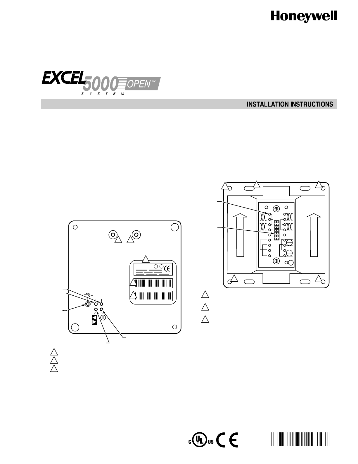
network connectors. See Fig. 1 for front panel view.
®
(E-Bus) network. The
BA
1
1
2
ULU
LPR-10
L
The router is installed in a Type 2 base plate. Wiring
connections are presented in Table 1. Specifications for the
router are shown in Table 2. Network and power are
connected to screw terminals located on a Type 2 base plate.
The router is plugged into the base plate. No wiring is ever
connected directly to the router. A writing space is provided
on the back of the base plate for recording the date of
installation and other important information. See Fig. 2 for
front view of base plate. See Fig. 3 for rear view of base
plate.
2
TEST
POINTS
1
3
BA
INTERFACE
CONNECTOR
2
SERVICE
LEDs
CHANNEL A
CHANNEL B
SERVICE
SWITCH
PACKET ACTIVITY LED ROUTER
TRANSFERRING PACKETS: FLASHING
1
OUTLET ACCESS JACKS; USE FOR ACCESS TO L
2
ROUTER INTERFACE MODEL AND SOFTWARE REVISION NUMBERS.
PEEL-OFF CODE 39 FORMAT BAR CODE OF ROUTER INTERFACE
3
®
Neuron
CHIP ID NUMBER.
B
A
3
3
POWER LED:
POWER ON: ILLUMINATED
CONTINUOUSLY
ONWORKS
BUS.
Fig. 1. Q7751A Router front plate.
®U.S. Registered Trademark
Copyright © 1999 Honeywell Inc. • All Rights Reserved
M16383
2
1
THREADED SCREW HOLES FOR ATTACHING ROUTER INTERFACE TO
BASE PLATE. USE 8-32, 3/8 IN. SCREW, Echelon 205-0130-01 OR EQUAL.
0.230 IN. HOLES FOR ATTACHING BASE PLATE TO ELECTRICAL BACK
2
BOX OR SUB-PANEL.
0.180 X 0.280 IN. HOLE FOR THE ATTACHING BASE PLATE TO
3
ELECTRICAL BACK BOX OR SUB-PANEL. USE 6-32, FLAT-HEAD,
3/8 IN. MINIMUM SCREW.
1
M16381
Fig. 2. Q7751A front view of base plate.
95- 7510- 3
Page 2
Q7751A ROUTERS
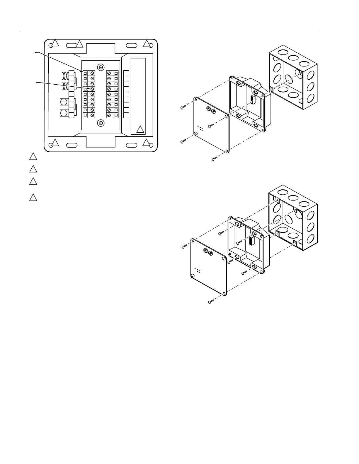
WIRE
ENTRY
TERMINAL
SCREW,
TIGHTENING
TORQUE 4
LBS. IN.
1
2
3
4
1
2
THREADED SCREW HOLES FOR ATTACHING ROUTER INTERFACE TO
BASE PLATE. USE 8-32, 3/8 IN. SCREW, Echelon 205-0130-01 OR EQUAL.
0.230 IN. HOLES FOR ATTACHING BASE PLATE TO ELECTRICAL BACK
BOX OR SUB-PANEL.
0.180 X 0.280 IN. HOLE FOR THE ATTACHING BASE PLATE TO
ELECTRICAL BACK BOX OR SUB-PANEL. USE 6-32, FLAT-HEAD,
3/8 IN. MINIMUM SCREW.
WRITING SPACE FOR INSTALLER. USE FINE POINT
SANFORD SHARPIE MODEL 30001 OR EQUAL.
3
1
23456789
11 12 13 14 15 16 17 18
10
2
4
1
M16382
Fig. 3. Q7751A rear view of base plate.
The Type 2 base plate is keyed to prevent accidental
insertion of an incorrect module. The router is attached to
the base plate with two 8-32 x 3/8 in. screws (provided).
The Type 2 base plate mounts to either a suitable U.S. four
in. square, two in. deep (10.16 cm x 5.08 cm) electrical
box, U.S. double gang electrical box or an IP-65 (NEMA 4)
enclosure. See Fig. 4 and 5.
4 IN. SQUARE
ELECTRICAL
BOX
BASE PLATE
ROUTER MODULE
M16384
Fig 4. Four in. square, two in. deep electrical box
mounting configuration.
DOUBLE GANG
ELECTRICAL BOX
BASE PLATE
ROUTER MODULE
Fig 5. Double gang two in. deep electrical box
mounting configuration.
95-7511—2 2
M16385
Page 3

Q7751A ROUTERS
Table 1. Router Wiring Connections.
Screw Terminal Wiring Connection
1 and 2 Incoming network wiring, polarity insensitive; CHANNEL A.
3 and 4 Outgoing network wiring, polarity-insensitive; CHANNEL A.
5 and 14 Cable shields; terminals 5 and 14 are internally connected.
6 and 7 Incoming power wiring 16 to 30 Vac or Vdc at 2.0 VA, polarity-insensitive. If using dc power, maintain
continuity of the power polarity throughout the network. Terminals 6 and 8 should be the same polarity.
Terminals 7 and 9 should be the same polarity.
10 and 12 Unused
Jumpered together internally; can be used to land extra wires.
11 and 13 Jumpered together internally; can be used to land extra wires.
15 and 16 Incoming network wiring, polarity insensitive; CHANNEL B.
17 and 18 Outgoing network wiring, polarity-insensitive; CHANNEL B.
Table 2. Router Specifications.
Function Description
Processor Two Echelon Neuron® 3150 chips. 10 Mhz.
Service function Recessed service switch, service LED. Dual tear-off bar code Neuron® ID self-adhesive tag for application
to redline drawings in the field.
Transceiver type Depends on model. FTT-10 for Q7751A2010
TP-78 for Q7751A1012
Network connector Ten orange screw terminals, non-removable, wire clamp style. Supports 12 to 24 AWG (4 to 0.27 mm2)
wire, shielded or unshielded daisy-chained cable. Two phone plug connectors are front panel accessible;
one per channel.
Input power 16 to 30 Vac or Vdc at 2.0 VA, internally isolated power supply.
Power connector Four black screw terminals, non-removable, wire clamp style. Supports 12 to 24 AWG (4 to 0.27 mm2)
daisy-chained wire.
Mounting Use with suitable back plate. Electrical box type or wall/35 mm DIN type.
Temperature -40 to +185oF (-40 to +85oC) operating and non-operating.
Humidity 10 to 95% RH at 122oF (50oC).
EMI FCC A, CE Mark
Safety agency UL 916
INSTALLING THE ROUTER
Install the router using the following steps:
1. Make sure the Type 2 base plate is correctly wired,
installed, and fastened to the electrical enclosure.
2. Check for continuity on all network and power wiring.
3. Make sure all network channels are terminated with
the correct number and type of terminator. Either one
or two terminator(s) can be installed in unused screw
terminals at the end of a network run.
4. Insert the router into the Type 2 base plate.
a. Align the network access jacks on the router
with the arrowhead on the Type 2 base plate
(the arrow should point toward the jacks).
b. Firmly press router into the base plate to make
sure the module is properly seated in its base
plate connector.
NOTE: The router can be hot plugged. There is no
need to disconnect power when installing
the module. If power is present, the Power
LED lights. If power is not present, the
Power LED is off.
5. Screw the two 8-32 x 3/8 in, (9.5 mm) screws into the
threaded inserts in the base plate.
6. Configure the router as described in the appropriate
software user guide.
7. See Troubleshooting section if necessary.
3 95-7510—3
Page 4

Q7751A ROUTERS
TROUBLESHOOTING
Table 3 contains common troubleshooting symptoms and
possible reasons and actions for repair.
Table 3. Troubleshooting symptoms and solutions.
Symptom Diagnosis
Power LED lit This is the normal LED state with node powered.
Power LED unlit Power supply that provides power to the module has lost primary power. Check power supply
outlet for power.
Power wiring not correctly connected to module. Use a meter to check for power on base plate
power terminals.
Input voltage is too low due to excessive load on the power supply that provides power to the
module because of excessively long cabling or power wiring that is shorted. Use a meter to
check for the correct voltage level on the base plate power terminals. Correct wiring length if too
long. Repair or replace faulty power cable.
Service LED unlit This is the normal state of the LED for a configured module.
Service LED flashing The module is not configured. This is the normal state for a new module. Commission the
module using the software tool.
No network communications Network wiring not connected correctly to the module.
Network cabling shorted, open, or otherwise damaged. Use continuity tester to check cabling.
Router(s) on network are not commissioned or powered.
Incorrect router channel type installed on channel.
Erratic or improper network
communications
Network wiring not securely connected to base plate terminals. The optimum tightening torque
for a base plate screw terminal is 4 lb/in. (0.5N/m) maximum.
Module not properly seated in the base plate. Make sure the module is pressed firmly into the
base plate and secured with fixing screws.
Use E-Bus Wiring Guidelines, form 74-2865.
Improper network cabling. In some cases, it is possible to correct network communications by
installing the Q7740A or Q7740B repeater in series with the network cabling. In other cases, the
cabling must be replaced with an approved cable.
Too many nodes on a channel. See the appropriate software user guide for channel limitations.
Controllers or devices are connected to the wrong channel of a router. Make sure the correct
types of controllers or devices are connected to the two router channels.
L
ONWORKS® is a registered trademark of Echelon® Corporation.
Home and Building Control Home and Building Control Home and Building Control Products
Honeywell Inc. Honeywell Limited-Honeywell Limitee Honeywell AG
Honeywell Plaza 155 Gordon Baker Road Böblinger Straße 17
P.O. Box 524 North York Ontario D-71101 Schönaich
Minneapolis, MN 55408-0524 M2H 3N7 Phone (49-7031) 637-01
Fax (49-7031) 637-493
95-7510—3 J.D. Rev. 5-99
Printed in U.S.A. on recycled
paper containing at least 10%
post-consumer paper fibers.
www.honeywell.com
 Loading...