

Page 1
Q7300L
Series 2000 Commercial
Thermostat Subbases
INSTALLATION INSTRUCTIONS
APPLICATION
The Q7300L Thermostat Subbase is used with the
T7300D,F Thermostat to provide electronic control of
commercial 24 Vac single zone HVAC equipment. The
T7300/Q7300L is designed for heat-cool applications using
a valve and valve actuator combination for hydronic
heating. See Table 1. It can also be used to control singlestage conventional heating systems. It provides two-speed
fan control. Terminals are provided for the T7047 Remote
Sensor or the T7147 Remote Sensor and Override
Module. LEDs on the thermostat are prewired and labeled
to indicate heat and cool operation. See Fig. 9 and 10 for
hookup drawings. Refer to form 63-4355 for installation
and operation of the T7300/Q7300.
Table 1. Valve and Valve Actuator Combinations.
Valve Model Valve Actuator Model
V5011A, C ML7984A3019
V5011F, G ML7984A3001
V5013A, C ML7984A3019
V5013F ML7984A3001
IMPORTANT
The valve will not close if the wrong valve and
valve actuator combination is used.
Electrical Rating:
20 to 30 Vac, 50/60 Hz.
System Current :
6 VA maximum at 30 Vac, 50 or 60 Hz.
Output Relay Current:
See Table 2.
Table 2. Maximum Amps at 30 Vac.
Relay Running (A) Inrush (A)
Fan 1.6 3.5
Heat 1.6 3.5
Cool 1.6 7.5
Auxillary (Economizer) 1.6 3.5
Temperature:
Ratings:
Operating Ambient: 40°F to 110°F (4°C to 43°C).
Shipping: -30°F to +150°F (-34°C to +65°C).
Display Accuracy:
+1°F (+0.5°C).
Setpoint:
Range: 45°F to 95°F (7°C to 35°C).
Differential: 2°F (1°C).
Humidity Ratings:
5% to 90% RH, noncondensing.
RECYCLING NOTICE
If this control is replacing a control that contains
mercury in a sealed tube, do n
control in the trash
Contact your local waste management authority for
instructions regarding recycling and the proper
disposal of the old thermostat.
ot
place your old
INSTALLATION
When Installing this Product…
1. Read these instructions carefully. Failure to follow
the instructions can damage the product or cause a
hazardous condition.
2. Check the ratings given in the instructions and on
the product to make sure the product is suitable for
your application.
3. Installer must be a trained, experienced service
technician.
4. After completing installation, use these instructions
to check out the product operation.
® U.S. Registered Trademark
Copyright © 1996 Honeywell Inc. • • All Rights Reserved
X-XX UL
62-0131-2
Page 2
Q7300L SERIES 2000 COMMERCIAL THERMOSTAT SUBBASE
NO
NO
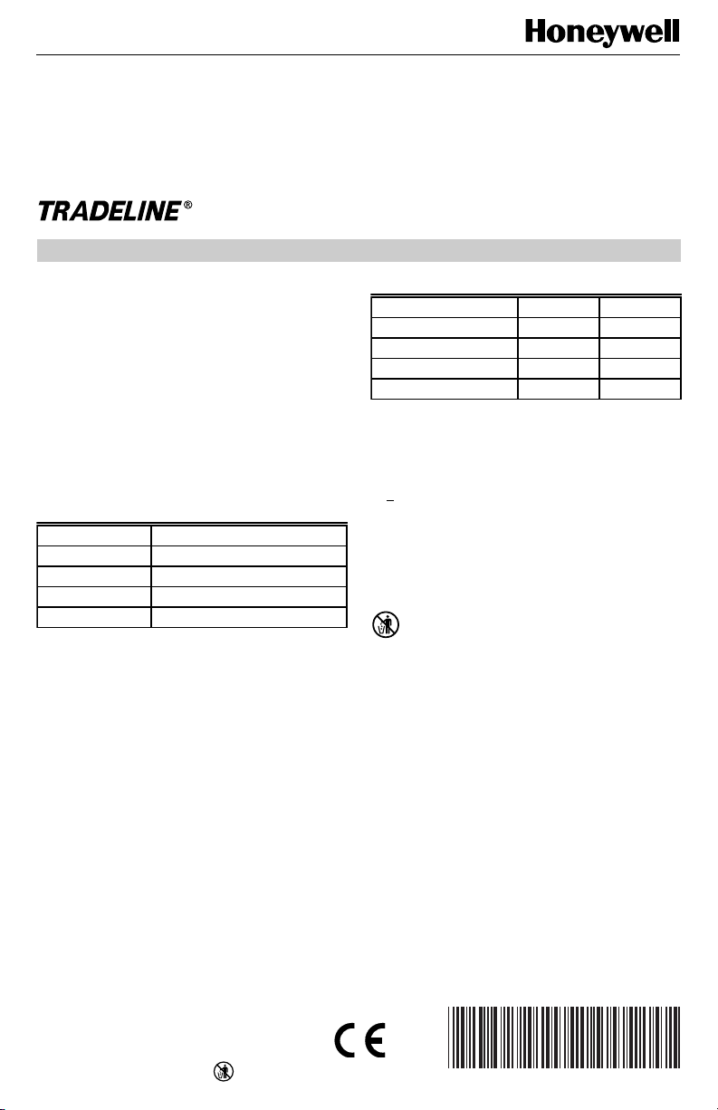
Fig. 1. Typical location of thermostat or remote-mounted sensor.
Location
Subbase without Remote-Mounted
Temperature Sensor
Install the thermostat about 5 ft (1.5m) above the floor in
an area with good air circulation at average temperature.
See Fig. 1.
Do not install the thermostat where it can be affected by:
— drafts, or dead spots behind doors and in corners.
— hot or cold air from ducts.
— radiant heat from sun or appliances.
— concealed pipes and chimneys.
— unheated (uncooled) areas such as an outside wall
behind the thermostat.
Subbase with Remote-Mounted
Temperature Sensor(s)
If only the remote-mounted temperature sensor(s) is used
to sense and control room temperature, then install the
thermostat in an area that is accessible for setting and
adjusting the temperature and settings.
If both the subbase and remote-mounted temperature
sensor(s) are used to sense and control room temperature, then install the subbase about 5 ft above the floor in
an area with good air circulation.
Install the remote-mounted sensor(s) about 5 ft (1.5m)
above the floor in an area with good air circulation at
average temperature. See Fig. 1.
YES
5 FEET
(1.5 METERS)
Do not mount the sensor(s) where it can be affected by:
— drafts, or dead spots behind doors and in corners.
— hot or cold air from ducts.
— radiant heat from sun or appliances.
— concealed pipes and chimneys.
— unheated (uncooled) areas such as an outside wall
behind the thermostat.
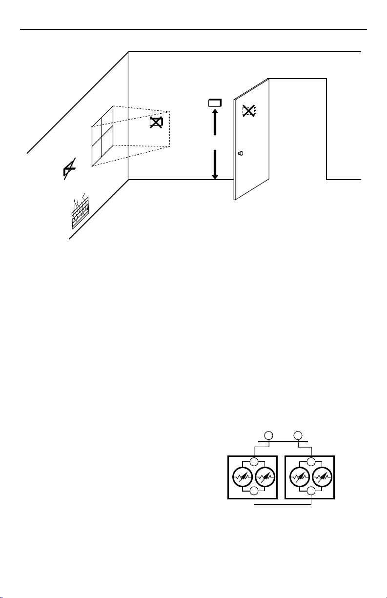
If more than one remote sensor are required, they must be
arranged in a temperature averaging network consisting of
two, three, four, five or nine sensors. See Fig. 2 through 6.
IMPORTANT
NO
M4823A
To avoid electrical interference, which can cause
erratic performance, keep wiring runs as short as
possible and do not run thermostat wires
adjacent to the line voltage electrical distribution
systems. Use shielded cable (Belden type 8762
or equivalent for 2-wire and Belden type 8772 or
equivalent for 3-wire). The cable shield must be
grounded only at the controlled equipment case.
SUBBASE
TT
T7047GT7047G
T
T
Fig. 2. Two T7047G Sensors providing
temperature averaging network for
T7300/Q7300 Thermostat/Subbase.
T
T
M4838
62-0131—2
2
Page 3
Q7300L SERIES 2000 COMMERCIAL THERMOSTAT SUBBASE
SUBBASE
TT
T7047C
TT
T7047G
T7047C
TT
Fig. 3. Two T7047C Sensors and one T7047G Sensor
providing temperature averaging network for T7300/
Q7300 Thermostat/Subbase.
TT
T7047C
TT
T7047C
TT
Fig. 4. Four T7047C Sensors providing
temperature averaging network for
T7300/Q7300 Thermostat/Subbase.
SUBBASE
TT
T7047G
T7047G
TT
M4839
SUBBASE
T7047C
TT
T7047C
TT
M4840
SUBBASE
TT
T7047C
TT
T7047C
TT
T7047C
TT
Fig. 6. Nine T7047C Sensors providing
temperature averaging network for
T7300/Q7300 Thermostat/Subbase.
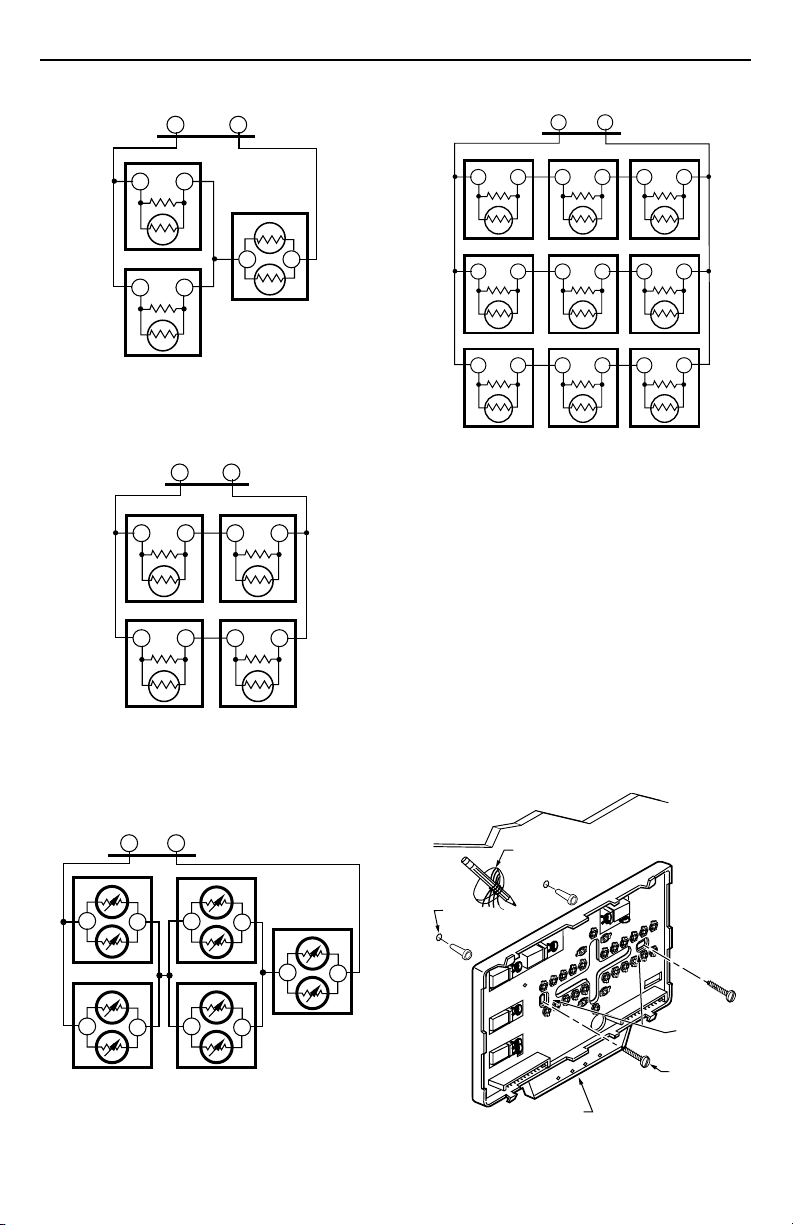
Mounting Subbase
The subbase mounts horizontally on the wall or a 2 in. x 4 in.
wiring box. Position the subbase horizontally on the wall or
on a 2 in. x 4 in. wiring box.
1. Position and level the subbase or wallplate (for
appearance only). The thermostat functions properly
even when not level.
2. Use a pencil to mark the mounting holes. See Fig. 7.
3. Remove the subbase or wallplate from the wall and
drill two 3/16 inch holes in the wall (if drywall) as
marked. For firmer material such as plaster or wood,
drill two 7/32 inch holes. Gently tap anchors (provided) into the drilled holes until flush with the wall.
4. Position the subbase over the holes, pulling wires
through the wiring opening.
5. Loosely insert the mounting screws into the holes.
6. Tighten mounting screws.
T7047C
TT
T7047C
TT
T7047C
TT
WIRES
THROUGH WALL
T7047C
TT
T7047C
TT
T7047C
TT
M4842
WALL
T
T7047G
T
Fig. 5. Five T7047G Sensors providing
temperature averaging network for
T7300/Q7300 Thermostat/Subbase.
T
T
T7047G
T
T
T7047G
T
T
WALL
ANCHORS
(2)
T
T
MOUNTING
HOLES
M4841
LEDS
MOUNTING
SCREWS
M10237
Fig. 7. Mounting the subbase.
3
62-0131—2
Page 4

Q7300L SERIES 2000 COMMERCIAL THERMOSTAT SUBBASE
WIRING SUBBASE
All wiring must comply with local electrical codes and ordinances. Follow equipment manufacturer wiring instructions when
available. Refer to Fig. 9 and 10 for typical hookups. A letter code is located near each terminal for identification. See
Table 3 for terminal descriptions and system action.
Table 3. Terminal Descriptions and Conditions.
Standard Terminal
Designations Typical Connection Function Terminal Type
A1, A2 Damper Control Relay. input, output 24V powered
BM ML7984 Actuator connection. No call for heat, valve
closed during occupied periods and open during
unoccupied periods.
output —
C1, C2, C3, C4, C5 Communication input for T7147. — —
FC Fan control Transformer. input —
GH High speed fan output. Activated during calls for cooling. output 24V powered
GL Low speed fan output. Activated on calls for heat and
P1, P2 Pump Interlock Relay. Operates circulator pump in
fan On selection.
hydronic heat or energizes conventional heat system.
output 24V powered
input, output 24V powered
R 24V System Transformer input —
RM ML7984 Actuator connection. No call for heat, valve
closed. Call for stage 1 heat, valve approximately onehalf open. Call for stage 2 heat, valve fully open.
——
T, T Remote sensor input for T7047 or T7147. — —
X Heating transformer common input —
Y Cool call 24V output on Y —
contact
contact
contact
contact
CAUTION
Disconnect power before wiring to prevent
electrical shock or equipment damage.
1. Loosen the terminal screws on the subbase and
connect the system wires. See Fig. 8.
IMPORTANT
Use 18-gauge, solid-conductor color-coded
thermostat cable for proper wiring. If using 18gauge stranded wire, no more than ten wires can
be used. Do not use larger than 18-gauge wire.
2. Securely tighten each terminal screw.
3. Push excess wire back into the hole.
4. Plug the hole with nonflammable insulation to
prevent drafts from affecting the thermostat.
NOTE: After wiring, check that all connections are tight
and secure. See Fig. 8. Loose or intermittent wire
connections cause inconsistent system operation.
62-0131—2
FOR STRAIGHT
FOR WRAPAROUND
INSERTION STRIP
7/16 IN. (11 MM).
INSERTION STRIP
5/16 IN. (8 MM).
M4826
Fig. 8. Proper wiring technique.
4
Page 5

Typical Wiring Hookups
R FC
AS AS
7
DISCHARGE
AIR
SENSOR
1
POWER SUPPLY. PROVIDE DISCONNECT MEANS AND OVERLOAD
PROTECTION AS REQUIRED.
INDEPENDENT FAN TRANSFORMER IS OPTIONAL. JUMPER FC TO R
2
WHEN SINGLE TRANSFORMER IS USED.
3
REFER TO ML7984 INSTRUCTIONS FOR TERMINAL CONNECTIONS.
4
T7047 HAS T-T TERMINALS ONLY.
5
180 2W RESISTOR MUST BE INSTALLED AS SHOWN.
A1 RM Y
ML7984
9
VALVE
ACTUATOR
3
L1
(HOT)
L2
1
TRANSFORMER
T5
R1
B3
T6
W
Fig. 9. Q7300L hookup for two-stage heating with three-position
ML7984 Valve Actuator/V5013 Valve and one-stage cooling.
DAMPER
CONTROL
RELAY
5
Q7300L SERIES 2000 COMMERCIAL THERMOSTAT SUBBASE
SUBBASE
C1 T
A2
PUMP
INTERLOCK
RELAY
COOLING
RELAY
GH
XP2P1 BM
GL
8
2
HIGH
SPEED
FAN
RELAY
LOW
SPEED
FAN
RELAY
6
CONNECT GND TO EARTH GROUND.
7
DISCHARGE AIR SENSOR IS ONLY COMPATIBLE WITH T7300F
THERMOSTAT.
8
JUMPER GH AND GL FOR SINGLE SPEED FAN.
9
SET THE DIP SWITCHES ON THE ML7984 TO MECHANICAL
SERIES 90 TO USE WITH Q7300L
C4 C3C5
CA4 CA3CA5
T7147 REMOTE COMFORT ADJUST MODULE
FAN
TRANSFORMER
C2
1
L1
(HOT)
L2
6
M4950B
T
TCA1 TCA2
4
GND
SUBBASE
C1 T
YP2
COOLING
RELAY
BM
RM
R X
L1
(HOT)
L2
P1 GH
A1 FC A2
HIGH-SPEED
FAN RELAY
1
1
2
3
4
GL
4
PUMP
INTERLOCK
RELAY
LOW
SPEED
FAN
RELAY
POWER SUPPLY. PROVIDE DISCONNECT MEANS AND OVERLOAD PROTECTION AS REQUIRED.
REFER TO T7147 INSTRUCTIONS FOR TERMINAL CONNECTIONS. T7047 HAS T-T TERMINALS ONLY.
CONNECT GND TO EARTH GROUND.
JUMPER GH AND GL FOR SINGLE SPEED FAN.
DAMPER
CONTROL
RELAY
C4 C3C5
CA4 CA3CA5
T7147 REMOTE COMFORT ADJUST MODULE
C2
Fig. 10. Q7300L hookup for single-stage conventional heating systems with single-stage cooling.
5
T
TCA1 TCA2
2
GND
3
M4941C
62-0131—2
Page 6

Q7300L SERIES 2000 COMMERCIAL THERMOSTAT SUBBASE
A.
Mounting Thermostat on Subbase
Mount the thermostat on the subbase after the subbase is
installed.
1. Engage tabs at the top of the thermostat and
subbase. Fig. 11.
2. Press lower edge of case to latch.
NOTE: To remove the thermostat from the wall,
first pull out at the bottom of the thermostat; then remove the top.
IMPORTANT
Refer to the thermostat installation instructions for
Installer Setup, Settings, Installer System Test
and Troubleshooting information.
ENGAGE TABS AT TOP OF THERMOSTAT AND SUBBASE OR WALLPLATE.
Fig. 11. Mounting thermostat on subbase.
B.
PRESS LOWER EDGE OF CASE TO LATCH.
M4824A
62-0131—2
6
Page 7

Q7300L SERIES 2000 COMMERCIAL THERMOSTAT SUBBASE
OPERATION
Table 4. T7300 Thermostat/Q7300L Subbase Sequence of Operation.
Mode
Occupied Any Auto — Thermostat in Occupied mode.
Occupied — On — Depends on last system. If cool is the last
Occupied Heat Auto Stage 1 heat Heat LED activated.
Occupied Heat Auto Stage 2 heat In hydronic applications, ML7984 is fully
Occupied Cool Auto Stage 1 cool Cool LED activated.
Unoccupied Any Any — Thermostat in Unoccupied mode.
Unoccupied Any On — Thermostat in Unoccupied mode.
a
Low speed fan is activated in the heat mode and high speed fan is activated in the cool mode.
System
Setting
Fan
Setting
Equipment
a
Call Action
Damper control relay energized.
system, then call is for high speed fan.
When heat is the last system, then call is
for low speed fan.
In hydronic applications, ML7984
approximately one-half open.
Pump interlock relay activated to energize
circulator pump.
In conventional applications, stage 1 heat
activated.
Low speed fan activated.
open. In conventional systems, no action.
Cooling relay activated.
High speed fan activated.
Damper control relay de-energized.
System fan operates at appropriate speed
with call for heat or cool equipment.
Loads
Energized
A2
GL or GH
A2, GL, RM,
P2
A2, GL, RM,
BM, P2
A2, GH, Y
—
—
Remote Temperature Sensing and Override
The subbase can be used with the T7147 Remote Sensors to sense temperature and provide the Occupied mode. The
subbase also can be used with the T7047 Remote Sensors if remote occupied control is not required.
7
62-0131—2
Page 8

Q7300L SERIES 2000 COMMERCIAL THERMOSTAT SUBBASE
Home and Building Control
Honeywell Inc.
Honeywell Plaza
P.O. Box 524
Minneapolis, MN 55408-0524
62-0131—2
62-0131—2 J.H. Rev. 7-97 www.honeywell.com/building/components
Home and Building Control
Honeywell Limited-Honeywell Limitée
155 Gordon Baker Road
North York, Ontario
M2H 3N7
8
Helping You Control Your World
®
 Loading...