

Honeywell Q7300H2003, Q7300H2011, Q7300H2029, Q7300H2037 Installation Instructions Manual
®
Q7300H Series 2000 Commercial
Thermostat Subbases
INSTALLATION INSTRUCTIONS
APPLICATION
The Q7300H Thermostat Subbases are used with
T7300F Thermostats to provide electronic control of
commercial 24 Vac single or multistage heat pump or
conventional heating and cooling systems. All models
have EB terminals for L
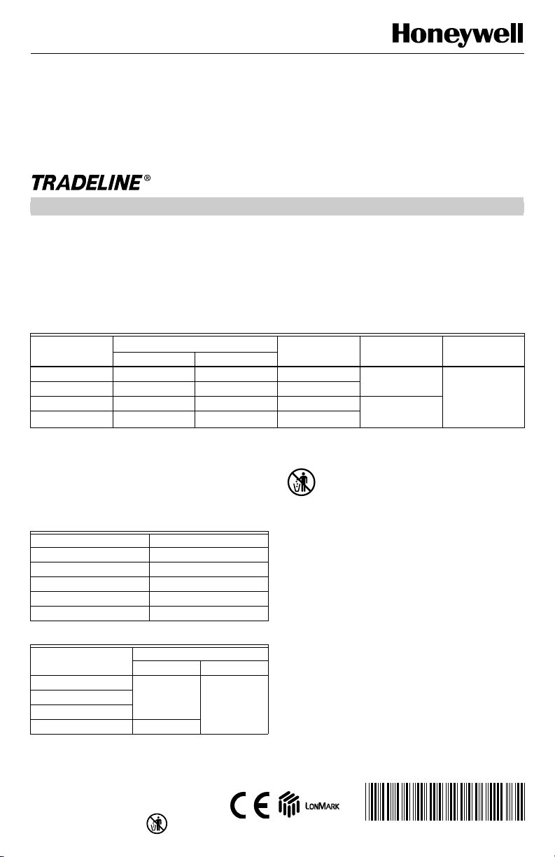
Model
Q7300H2003 3 2 10 Heat Pump T7300F
Q7300H2011 3 2 11
Q7300H2029 3 3 12 Conventional
Q7300H2037
a
Depends on model.
b
Designed for heat applications using a valve and valve actuator (see Table 2).
IMPORTANT
Table 2. Valve and Valve Actuator Combinations.
V5011A,C ML7984A3019
V5011F,G ML7984A3001
V5011N, V5013N ML7984A3019
V5013A,C ML7984A3019
V5013F ML7984A3001
Table 3. Output Relay Maximum Current (at 30 Vac).
Fan 3.5 2.0
Heat
Auxiliary (Economizer)
Cool 7.5
b
2113
The valve does not close unless correct
valve and valve actuator combination is used.
See Table 2.
Valve Model Valve Actuator Model
Relay
®
ONWORKS
network connections.
Table 1. Q7300 Subbase Description.
Maximum Stages
Maximum Current (in Amps)
Inrush Running
a
Terminals are also provided for the T7047 Remote
Sensor or the T7147 Remote Sensor and Override
Module. See Table 1. Select models are designed for
heat applications using a valve and valve actuator
combination for hydronic heating with 2-speed fan
control. See Table 4. All Q7300 Thermostat Subbases
require a common wire to the supply power.
Hookup Drawing Applications
MERCURY NOTICE
If this control is replacing a control that contains
mercury in a sealed tube, do not place your old
control in the trash.
Contact your local waste management authority
for instructions regarding recycling and the
proper disposal of the old thermostat.
Thermostat
INSTALLATION
When Installing this Product…
1. Read these instructions carefully. Failure to follow
the instructions can damage the product or cause
a hazardous condition.
2. Check the ratings given in the instructions and on
the product to make sure the product is suitable for
your application.
3. Installer must be a trained, experienced service
technician.
4. After completing the installation, use these
instructions to check out the product operation.
RequiredHeat Cool
® U.S. Registered Trademark
Copyright © 2001 Honeywell • • All Rights Reserved
®
62-0155-3
Q7300H SERIES 2000 COMMERCIAL THERMOSTAT SUBBASES
A
T
Location
Subbase Without Remote-Mounted
Temperature Sensor
Install the thermostat about 5 ft (1.5m) above the floor in
an area with good air circulation at average temperature.
See Fig. 1.
Do not install the thermostat where it can be affected by:
— Drafts, or dead spots behind doors and in corners.
— Hot or cold air from ducts.
— Radiant heat from sun or appliances.
— Concealed pipes and chimneys.
— Uncontrolled areas such as an outside wall behind the
thermostat.
Subbase With Remote-Mounted
Temperature Sensors
If only remote-mounted temperature sensors are
used to sense and control room temperature, install
the thermostat in an area accessible for setting and
adjusting the temperature and settings.
If both the subbase and remote-mounted temperature
sensor(s) are used to sense and control room
temperature, install the subbase about 5 ft above the
floor in an area with good air circulation. Install the
remote-mounted sensor(s) about 5 ft (1.5m) above the
floor in an area with good air circulation at average
temperature. See Fig. 1.
Do not mount the sensor(s) where it can be affected by:
— Drafts, or dead spots behind doors and in corners.
— Hot or cold air from ducts.
— Radiant heat from sun or appliances.
— Concealed pipes and chimneys.
— Uncontrolled areas such as an outside wall behind the
thermostat.
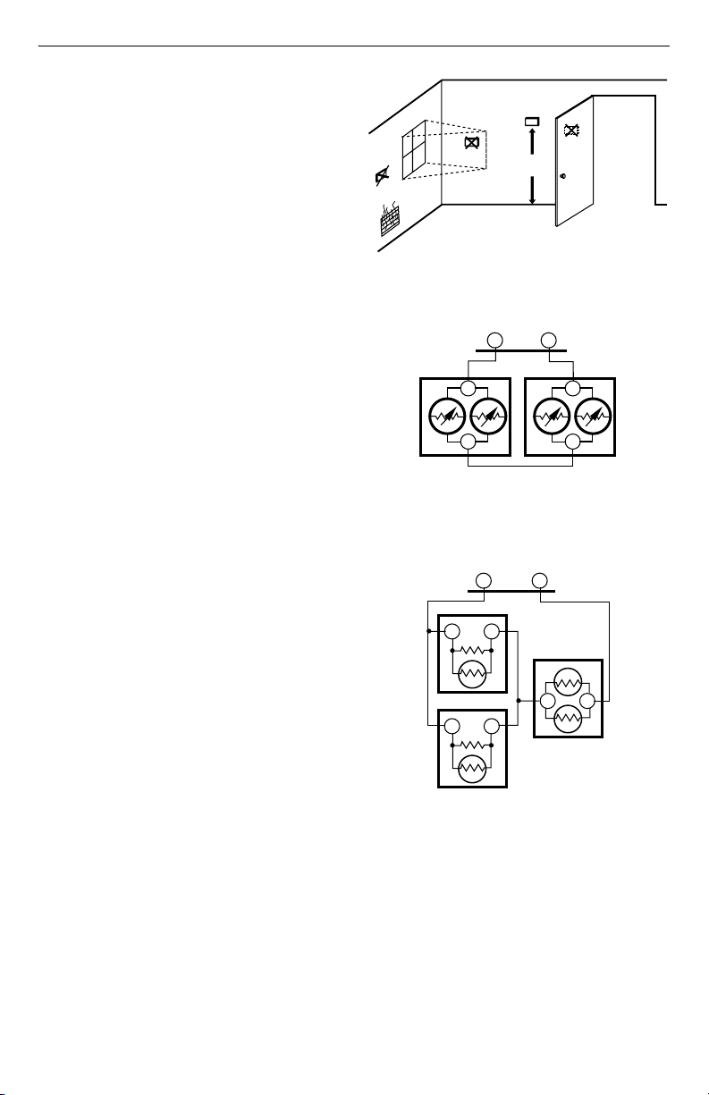
If more than one remote sensor is required, arrange them
in a temperature averaging network consisting of two,
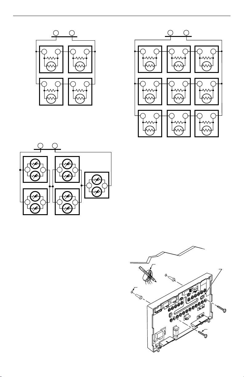
three, four, five or nine sensors. See Fig. 2 through 6.
IMPORTANT
To avoid electrical interference, which can
cause erratic performance, keep wiring runs
as short as possible and do not run thermostat
wires adjacent to the line voltage electrical
distribution systems. Use shielded cable
(Belden type 8762 or equivalent for 2-wire and
Belden type 8772 or equivalent for 3-wire). The
cable shield must be grounded only at the
controlled equipment case.
YES
NO
NO
Fig. 2. Two T7047G Sensors providing
Fig. 3. Two T7047C Sensors and one T7047G Sensor
providing temperature averaging network for
NO
5 FEET
(1.5 METERS)
Fig. 1. Typical location of thermostat
or remote-mounted sensor.
SUBBASE
TT
7047G
T
T
temperature averaging network for
T7300/Q7300 Thermostat/Subbase.
T7047C
TT
T7047C
TT
T7047G
T
T
SUBBASE
TT
T7047G
TT
M4839
M4838
T7300/Q7300 Thermostat/Subbase.
M4823
62-0155—3 2
TT
SUBBASE
T7047C
TT
T7047C
TT
Q7300H SERIES 2000 COMMERCIAL THERMOSTAT SUBBASES
SUBBASE
TT
T7047C
TT
T7047C
TT
T7047C
TT
T7047C
TT
Fig. 4. Four T7047C Sensors providing
temperature averaging network for
T7300/Q7300 Thermostat/Subbase.
SUBBASE
TT
T7047G
T
T
T7047G
T
T
Fig. 5. Five T7047G Sensors providing
temperature averaging network for
T7300/Q7300 Thermostat/Subbase.
T7047G
T
T7047G
T
T7047C
TT
T
T7047G
T
M4840
T
M4841
T7047C
TT
T7047C
TT
Fig. 6. Nine T7047C Sensors providing
temperature averaging network for
T7300/Q7300 Thermostat/Subbase.
T7047C
TT
T7047C
TT
T7047C
TT
T7047C
TT
M4842
Mount Subbase
Mount the subbase horizontally on the wall or on a
2 in. x 4 in. wiring box:
T
1. Position and level the subbase or wallplate (for
appearance only). The thermostat functions properly
even when not level.
2. Use a pencil to mark mounting holes. See Fig. 7.
3. Remove subbase or wallplate from the wall and
drill two 3/16 in. holes in the wall (if drywall) as
marked. (For firmer material such as plaster or
wood, drill two 7/32 in. holes.) Gently tap anchors
(provided) into drilled holes until flush with the wall.
4. Position the subbase over the holes, pulling wires
through the wiring opening.
5. Loosely insert the mounting screws into the holes.
6. Tighten the mounting screws.
WALL
WIRES
THROUGH WALL
MOUNTING
HOLES (2)
WALL
ANCHORS (2)
MOUNTING
SCREWS (2)
M16055
Fig. 7. Mounting the subbase.
3 62-0155—3
 Loading...