

Honeywell T7200D, T7200E, T7300F, Q7300, T7300D Product Data
...
T7200D,E, T7300D,E,F and Q7300
63-4355-2
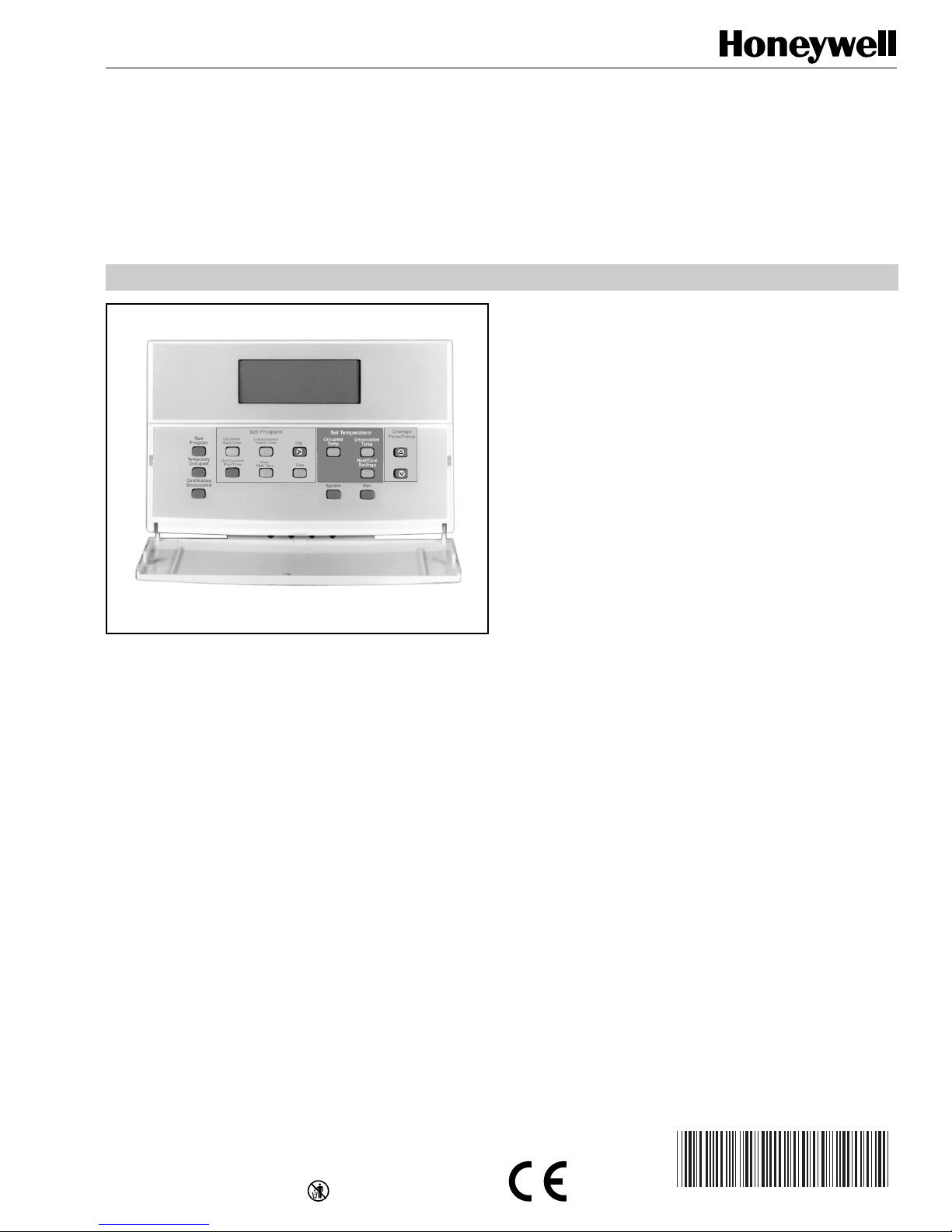
Series 2000 Programmable Commercial
Thermostats and Subbases
PRODUCT DATA
• Automatic or manual changeover models available.
• Universal Versaguard™ Thermostat guards available.
• Convenient overrides allow temporary setpoint changes.
• Keypad lockout available.
T7200D,E Thermostats
• Use on single-stage conventional (T7200D) or heat
pump (T7200E) applications.
T7300D,E Thermostats:
• Use on multistage conventional (T7300D) or heat
pump (T7300E) applications.
• Models available with remote sensor capability.
T7300F Thermostats:
• Use on single-stage or multistage system in
conventional or heat pump applications.
• Auxiliary contacts on Q7300 can be used to interface
with C7400/W7459 Economizer System for total
integration of rooftop control.
• Remote temperature sensors available f or use with
all models.
• Different levels of keypad lockout available.
APPLICATION
The T7200, T7300 Thermostats and Q7300 Subbases control
24 Vac commercial single zone heating, ventilating and air
conditioning (HVAC) equipment. In addition, the Q7300H
Communicating Subbase can communicate schedule
information and system instructions to other devices in a
LonWorks® network.
FEATURES
All Models:
• 7-day programming.
• Two Occupied and two Unoccupied periods per day.
• Individual heat and cool setpoints available for
Occupied and Unoccupied periods.
• Proportional plus Integral (P+I) control eliminates
temperature fluctuations.
• Intelligent Recovery® control automatically optimizes
equipment start times based on building load.
• Intelligent Fan™ feature energizes fan continuously in
the Occupied periods. Fan can also be configured for
conventional heat or electric heat fan operation.
Q7300 Subbase:
• Use with T7300D,E,F Thermostats.
• Auxiliary contacts can be used to interface with
C7400/W7459 Economizer System for total
integration of rooftop control.
• When used with the T7300F (revision 3 or later), the
Q7300H communicates with other network devices.
Contents
Application........................................................................... 1
Features .............................................................................. 1
Specifications ...................................................................... 2
Ordering Information ........................................................... 2
Installation ........................................................................... 5
Wiring Subbase or Wallplate............................................... 7
Settings ............................................................................... 9
Installer Setup ..................................................................... 10
Installer System Test ........................................................... 14
Programming....................................................................... 16
Operation ............................................................................ 20
General Operation Information............................................ 22
Troubleshooting Guide ........................................................ 23
Cross Reference ................................................................. 25
Wiring Diagrams.................................................................. 33
LonWorks® is a registered trademark of Echelon Corporation.
® U.S. Registered Trademark
Copyright © 1999 Honeywell Inc. • • All Rights Reserved
T7200D ,E, T7300D,E,F AND Q7300 SERIES 2000 PROGRAMMABLE COMMERCIAL THERMOSTATS AND SUBBASES
SPECIFICATIONS
T7200/T7300 Thermostats:
T7200 and T7300 Thermostats provide features listed in
Table 1.
IMPORTANT
The specifications given in this publication do not
include normal manufacturing tolerances. Therefore,
Q7300 Subbases:
Q7300 Subbases provide features listed in Table 2.
this unit might not exactly match the listed
specifications. This product is tested and calibrated
under closely controlled conditions, and some minor
differences in performance can be expected if those
conditions are changed.
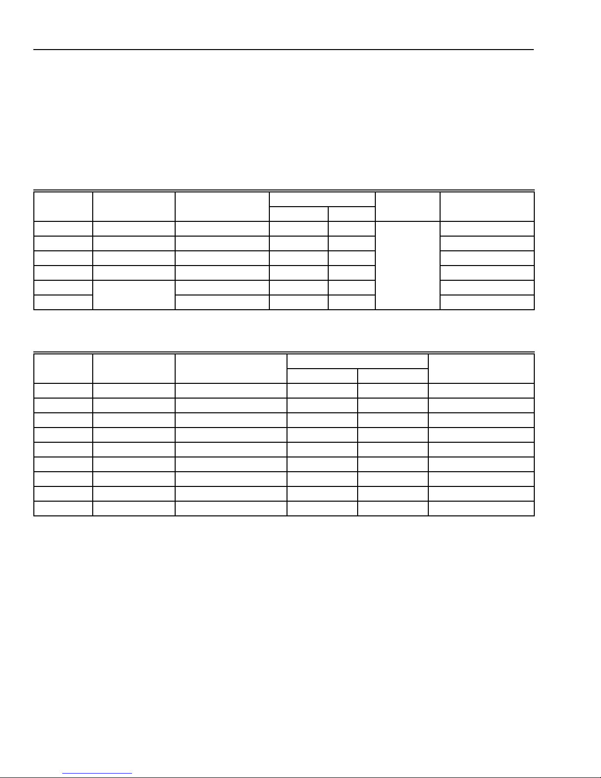
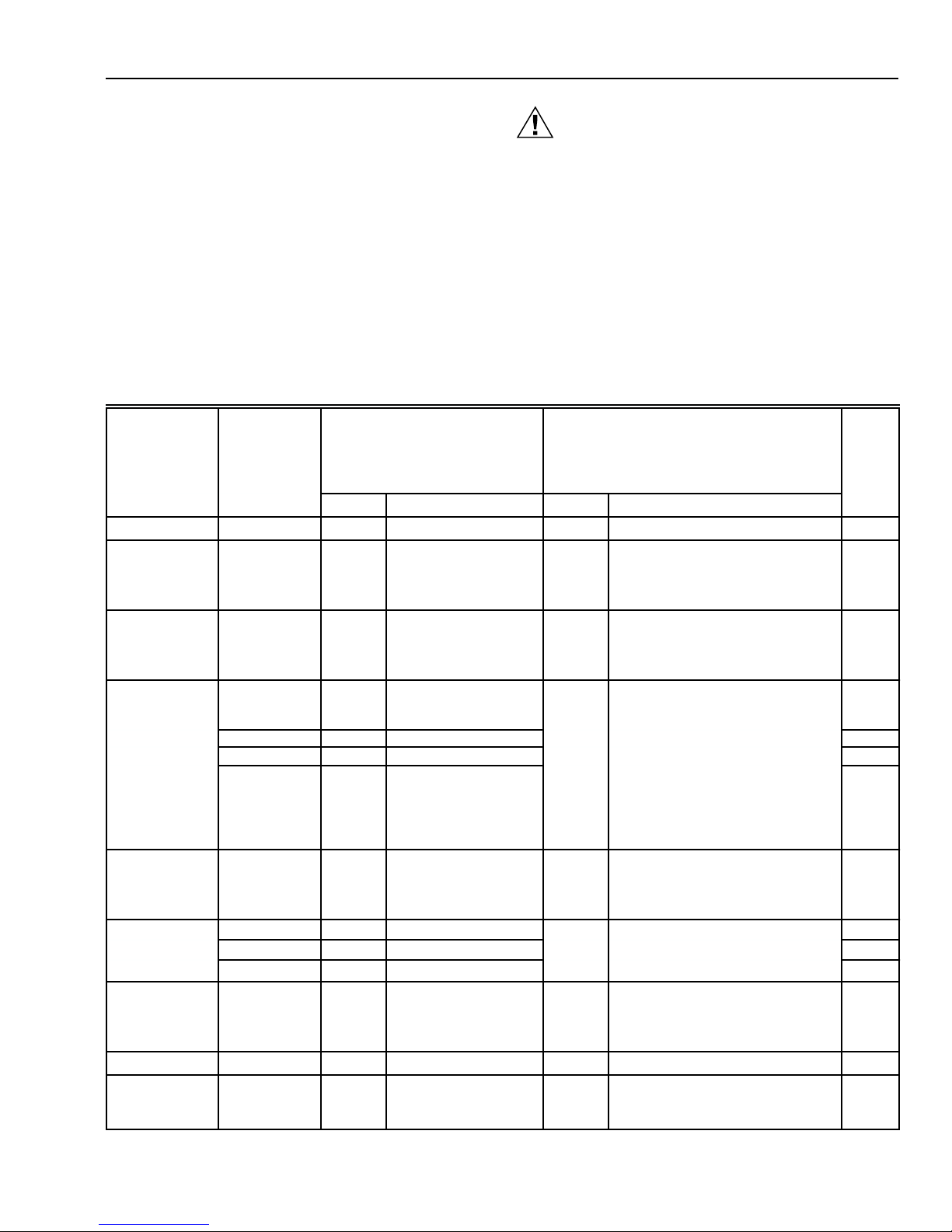
Table 1. T7200 and T7300 Thermostat Features.
Maximum Stages
Model Applications Subbase Required Heat Cool ChangeoverbHookup Drawing No.
T7200D Conventional None
T7200E Heat Pump None
a
a
11
11
Automatic
or Manual
19
20
T7300D Conventional Q7300A, G, L 3 3 21-22, 27, 33-34
T7300E Heat Pump Q7300C, D 3 2 23–26
T7300F
T7300F
a
Wallplate provided.
b
Configured in Installer Setup.
Conventional or
Heat Pump
Q7300A, C, D, G, L 3 3 21-27, 33-34
Q7300H — — 28-31
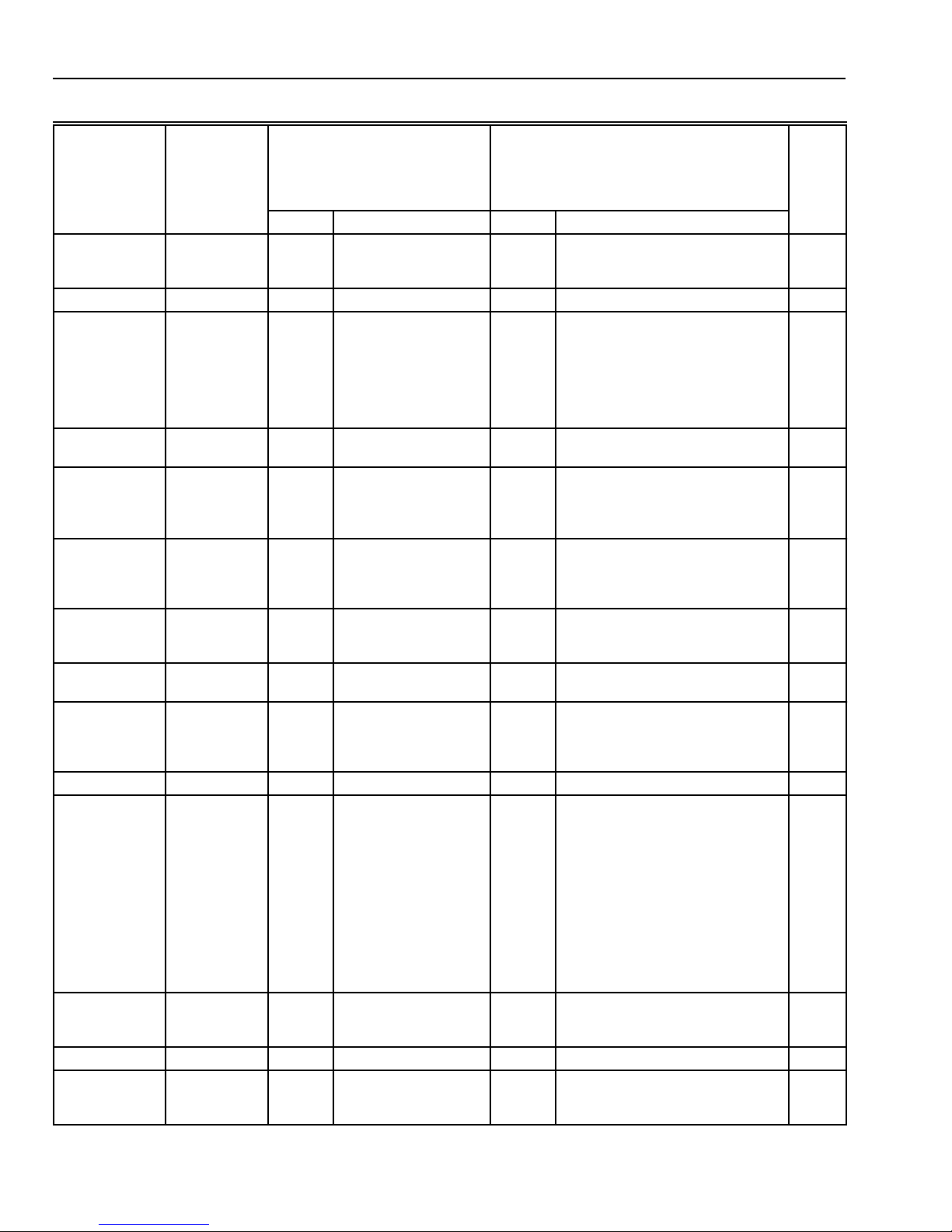
Table 2. Q7300 Subbase Features.
a
Drawing No.
Model Applications Thermostat
Q7300A
Q7300C
Q7300D
Q7300G
Q7300H
Q7300H
b
b
c
d
Conventional T7300D, F 2 2 21-22
b
Heat Pump T7300E, F 3 2 23–25
Heat Pump T7300E, F 3 2 26
b
Conventional T7300D, F 3 3 27
Heat Pump T7300F 3 2 28
Heat Pump T7300F 3 2 29
Required
Maximum Stages
Heat Cool Hookup
Q7300H Conventional T7300F 3 3 30
Q7300H Conventional T7300F 2 1 31
Q7300L Conventional
a
Wallplate only.
b
All subbases are down selectable and can be configured to
control fewer stages than the maximum allowed.
e
T7300D, F 2 1 33-34
c
With O/B terminals.
d
Without O/B terminals.
e
Used with ML7984 Actuator and V5011 or V5013 Valve.
ORDERING INFORMATION
When purchasing replacement and modernization products from your TRADELINE® wholesaler or distributor, refer to the
TRADELINE® Catalog or price sheets for complete ordering number.
If you have additional questions, need further information, or would like to comment on our products or services, please write or
phone:
1. Your local Home and Building Control Sales Office (check white pages of your phone directory).
2. Home and Building Control Customer Logistics
Honeywell Inc., 1885 Douglas Drive North
Minneapolis, Minnesota 55422-4386 (612) 951-1000
In Canada—Honeywell Limited/Honeywell Limitée, 155 Gordon Baker Road, North York, Ontario M2H 3N7.
International Sales and Service Offices in all principal cities of the world. Manufacturing in Australia, Canada, Finland, France,
Germany, Japan, Mexico, Netherlands, Spain, Taiwan, United Kingdom, U.S.A.
63-4355—2 2

T7200D ,E, T7300D,E,F AND Q7300 SERIES 2000 PROGRAMMABLE COMMERCIAL THERMOSTATS AND SUBBASES
Electrical Ratings:
24 Vac, 50/60 Hz.
20 to 30 Vac, 50/60 Hz.
Batteries:
No batteries required.
Auxiliary Heat and Emergency Heat Indication:
Thermostat display indicates when Auxiliary Heat or
Emergency Heat are activated.
Loss of Power:
The thermostat will maintain programmed times and
temperatures for the life of the product. The clock and day
information is retained for a minimum of two hours.
Light Emitting Diodes (LEDs):
Two user-defined LEDs (not available on Q7300H).
Two defined (CHECK and MAINTENANCE) LEDs on select
models.
Two additional LEDs available on select models.
System Current Draw:
6 VA maximum at 30 Vac, 50/60 Hz.
Output Relay Draw:
See T able 3.
Table 3. Maximum Amps at 30 Vac.
Relay Running (A) Inrush (A)
Fan 1.6 3.5
Heat (all stages) 1.6 3.5
Cool (all stages) 1.6 7.5
Auxiliary (Economizer) 1.6 3.5
Temperature:
Ratings:
Operating Ambient: 40°F to 110°F (4°C to 43°C).
Shipping: -30°F to +150°F (-34°C to +65°C).
Display Accuracy: ±1°F (±0.5°C).
Setpoint:
Range: 45°F to 95°F (7°C to 35°C).
Deadband: 2°F (1°C).
Default Settings: see Table 4.
Table 4. Default Setpoints.
Control Occupied Unoccupied
Heating 70°F (20°C) 55°F (13°C)
Cooling 78°F (25.5°C) 90°F (32°C)
Table 5. T emperature Offset.
Temperature Range 18 AWG 20 AWG 22 AWG
50-90°F -0.4°F -0.7°F -1.0°F
10-32°C -0.3°C -0.4°C -0.6°C
Minimum Stage Operation Time:
Minimum On (Heat and Cool): factory setting 2 minutes;
option 0 minutes.
Minimum Off (Cool and Heat Pump): factory setting
4 minutes; option 0, 1, 3, 5 minutes.
Humidity Ratings:
5% to 90% RH, noncondensing.
Clock Accuracy:
+1 minute per month.
Finish:
Taupe color.
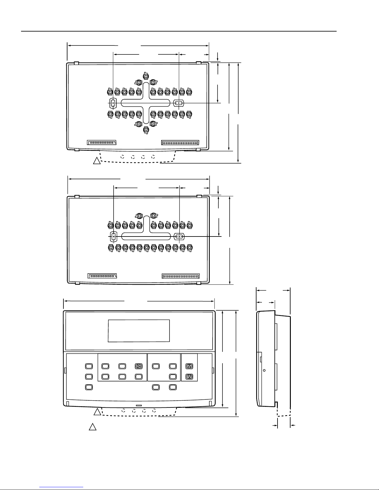
Dimensions:
See Fig. 1.
Mounting Means:
T7200 Thermostat mounts on a wallplate. The T7300 Thermostat mounts on a Q7300 Subbase. The wallplate and
subbase mount horizontally on a wall or outlet box with two
no. 6 x 32 screws (included).
Accessories:
C7150B1004 Discharge Air Sensor (form 63-2072).
C7400 Enthalpy Sensor (form 63-2140).
M7415 Damper Actuator (form 63-2100).
ML7984 Valve Actuator (form 95C-10753).
Q7760A Serial LonTalk® Adapter
R8222 Switching Relay (form 60-2056).
T675A Temperature Control (form 60-2200).
T7022A1010 Remote Temperature Sensor (form 60-0247).
T7047C Remote Temperature Sensor (form 62-3050).
T7047G Remote Temperature Sensor (form 62-3050).
T7147A Remote Temperature Sensor and Override Module
(form 62-3049).
W859F Packaged Economizer (form 63-2476).
W950A System Supervisor (form 60-2351).
W7459 Economizer Logic Module (form 63-2141).
W6210/W7210 Economizer (form 63-2528).
Approvals:
European Community Mark (CE) Listed.
Q7300H only: LonMark® Functional Profile No. 8060,
Thermostat Object (type 09).
Remote Sensor Wiring Temperature Offset:
Temperature offset occurs with 500 ft (157m) to 1000 ft (305m)
of 2-wire cable. See T able 5.
RECYCLING NOTICE
If this control is replacing a control that contains
mercury in a sealed tube, do
control in the trash.
Contact your local waste management authority for
instructions regarding recycling and the proper
disposal of the old thermostat.
not
place your old
63-4355—23
T7200D ,E, T7300D,E,F AND Q7300 SERIES 2000 PROGRAMMABLE COMMERCIAL THERMOSTATS AND SUBBASES
6-3/4 (172)
3-1/4 (82)
1-3/8 (35)
1/16 (2)
1-7/8
(47)
4-1/8
(105)
4-3/4
(121)
1
Q7300A,C,D,G,L
6-11/16 (170)
3-3/16 (77)
1-3/8 (35)
1/16 (2)
1-7/8
(47)
M16292
Q7300H
7-5/16 (186)
Run
Program
Temporary
Occupied
Continous
Unoccupied
Occupied
Start Time
Set Current
Day/Time
Set Program
Unoccupied
Start Time
Clear
Start Time
Day
Copy
Set Temperature
Occupied
Temp
System
Unoccupied
Temp
Heat/Cool
Settings
Fan
1
T7200D,E; T7300D,E,F
1 T7200 WALLPLATE DOES NOT HAVE THE LED EXTENSION
Fig. 1. Dimensions of T7200, T7300 and Q7300 in in. (mm).
Change
Time/Temp
4-5/8
(117)
4-1/8
(105)
5 (127)
7/8
(22)
1-11/16
(43)
9/16
(14)
63-4355—2 4
T7200D ,E, T7300D,E,F AND Q7300 SERIES 2000 PROGRAMMABLE COMMERCIAL THERMOSTATS AND SUBBASES
INSTALLATION
Q7300 Subbase with Remote-Mounted
Temperature Sensor(s)
When Installing this Product…
1. Read these instructions carefully. Failure to follow the
instructions can damage the product or cause a
hazardous condition.
2. Check the ratings given in the instructions and on the
product to make sure the product is suitable for your
application.
3. Installer must be a trained, experienced service
technician.
4. After completing installation, use these instructions to
check out the product operation.
If only the remote-mounted temperature sensor(s) is used to
sense and control room temperature, then install the
thermostat in an area that is accessible for setting and
adjusting the temperature and settings.
If both the subbase and remote-mounted temperature
sensor(s) are used to sense and control room temperature,
then install the subbase about 5 ft above the floor in an area
with good air circulation.
Install the remote-mounted sensor(s) about 5 ft (1.5m) above
the floor in an area with good air circulation at average
temperature. See Fig. 2.
Location
T7200 Wallplate or Q7300 Subbase without RemoteMounted Temperature Sensor
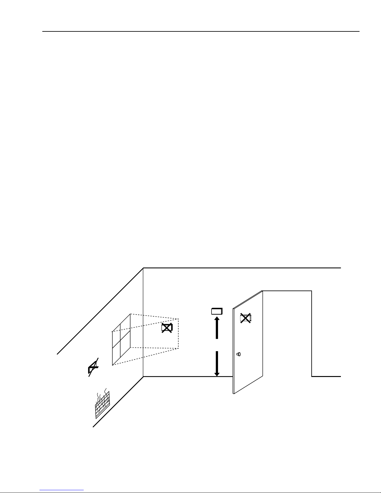
Install the thermostat about 5 ft (1.5m) above the floor in an
area with good air circulation at average temperature. See
Fig. 2.
Do not install the thermostat where it can be affected by:
— drafts, or dead spots behind doors and in corners.
— hot or cold air from ducts.
— radiant heat from sun or appliances.
— concealed pipes and chimneys.
— unheated (uncooled) areas such as an outside wall
behind the thermostat.
Do not mount the sensor(s) where it can be affected by:
— drafts, or dead spots behind doors and in corners.
— hot or cold air from ducts.
— radiant heat from sun or appliances.
— concealed pipes and chimneys.
— unheated (uncooled) areas such as an outside wall
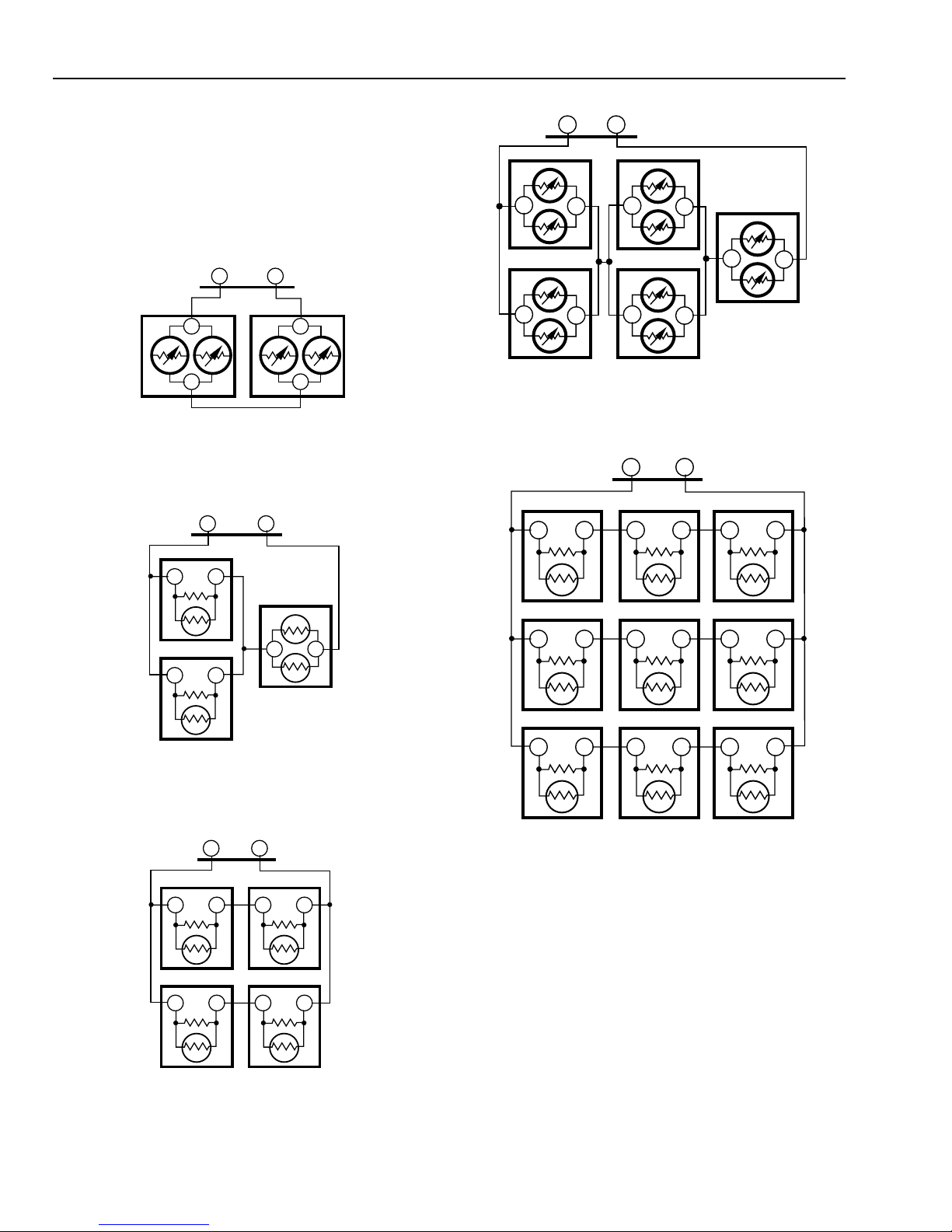
If more than one remote sensor are required, they must be
arranged in a temperature averaging network consisting of
two, three, four, five or nine sensors. See Fig. 3 through 7.
NOTES:
— When sensor averaging, the T7147A can be substituted
— Up to four T7147As can be used in parallel to place the
behind the thermostat.
for the T7047C. The T7147A includes OVERRIDE and
WARMER/COOLER keys.
thermostat in Temporary Occupied.
NO
Fig. 2. Typical location of thermostat or remote-mounted sensor.
NO
YES
5 FEET
(1.5 METERS)
NO
M4823A
63-4355—25
T7200D ,E, T7300D,E,F AND Q7300 SERIES 2000 PROGRAMMABLE COMMERCIAL THERMOSTATS AND SUBBASES
IMPORT ANT
To avoid electrical interference, which can cause
erratic performances, keep wiring runs as short as
possible and do not run thermostat wires adjacent to
the line voltage electrical distribution systems. Use
shielded cable (Belden type 8762 or equivalent for
2-wire and Belden type 8772 or equivalent for 3-wire).
The cable shield must be grounded only at the
controlled equipment case.
Fig. 3. Two T7047G Sensors providing
SUBBASE
TT
T7047GT7047G
T
T
T
T
M4838
temperature averaging network for
T7300/Q7300 Thermostat/Subbase.
SUBBASE
TT
T7047C
TT
T7047G
SUBBASE
TT
T7047G
T
T7047G
T
T7047G
T
T
T
T7047G
T
T
T7047G
T
Fig. 6. Five T7047G Sensors providing
temperature averaging network for
T7300/Q7300 Thermostat/Subbase.
SUBBASE
TT
T7047C
TT
T7047C
T7047C
TT
T7047C
T7047C
T7047C
T
TT
T
M4841
T7047C
TT
TT
M4839
Fig. 4. Two T7047C Sensors and one T7047G Sensor
providing temperature averaging network for
T7300/Q7300 Thermostat/Subbase.
SUBBASE
TT
T7047C
TT
T7047C
TT
T7047C
TT
T7047C
TT
M4840
Fig. 5. Four T7047C Sensors providing
temperature averaging network for
T7300/Q7300 Thermostat/Subbase.
TT
T7047C
TT
TT
T7047C
TT
TT
T7047C
TT
M4842
Fig. 7. Nine T7047C Sensors providing temperature
averaging network for T7300/Q7300 Thermostat/Subbase.
NOTE: When thermostat is configured for temperature
averaging network (remote and internal sensing), the
internal sensor has 50% authority of the averaged
temperature.
Mounting Subbase or Wallplate
The subbase or wallplate mounts horizontally on the wall or a
2 in. x 4 in. wiring box. Position the subbase or wallplate
horizontally on the wall or on a 2 in. x 4 in. wiring box.
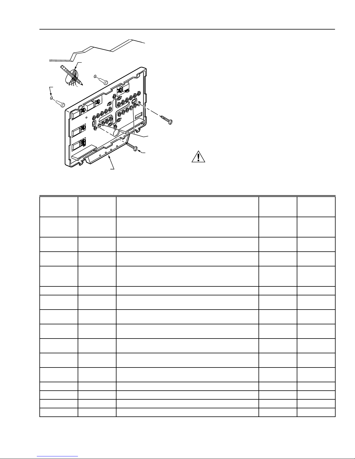
1. Position and level the subbase or wallplate (for
appearance only). The thermostat functions properly
even when not level.
2. Use a pencil to mark the mounting holes. See Fig. 8.
63-4355—2 6
T7200D ,E, T7300D,E,F AND Q7300 SERIES 2000 PROGRAMMABLE COMMERCIAL THERMOSTATS AND SUBBASES
3. Remove the subbase or wallplate from the wall and drill
two 3/16 inch holes in the wall (if drywall) as marked.
For firmer material such as plaster or wood, drill two
7/32 inch holes. Gently tap anchors (provided) into the
drilled holes until flush with the wall.
WIRES
THROUGH WALL
WALL
4. Position the subbase or wallplate over the holes, pulling
wires through the wiring opening.
5. Loosely insert the mounting screws into the holes.
WALL
ANCHORS
(2)
6. Tighten mounting screws.
WIRING SUBBASE OR WALLPLATE
All wiring must comply with local electrical codes and
ordinances. Follow equipment manufacturer wiring
MOUNTING
HOLES
MOUNTING
SCREWS
LEDS
Fig. 8. Mounting subbase or wallplate.
M10237
instructions when available. Refer to Fig. 19 through 32 for
typical hookups. A letter code is located near each terminal
for identification. Refer to Table 6 for terminal designations.
CAUTION
Electrical Shock Hazard.
Power supply can cause electrical shock.
Disconnect power before beginning installation.
Table 6. Terminal Designations and Descriptions.
Standard
Terminal
Designations
A1
Alternate
Terminal
Designations Typical Connection Function
A2
a
Dry auxiliary contacts for economizer control; A1 is
Output Dry contact
Terminal
Type
normally open during Unoccupied periods and closed
during Occupied periods.
A1, A2 — Damper control relay (Q7300L only). Input, Output 24V powered
contact
A2
A1
a
Dry auxiliary contacts for economizer control (A2 is
Input Dry contact
common).
A3 — Dry auxiliary contacts for economizer control; A3 is
Output Dry contact
normally open during Occupied periods and closed during
Unoccupied periods.
AS, AS — C7150B Discharge Air Sensor connection. Input —
B — Heating changeover valve. Output 24V powered
contact
C1, C2, C3,
— Communication input for T7147. Input Low power
C4, C5
E K Emergency heat relay. Output 24V powered
contact
EB, EB
—
Q7300H LonWorks® bus connection to LonWorks®
network.
Input, Output Communi -
cations
G F Fan relay. Output 24V powered
contact
O R Cooling changeover valve. Output 24V powered
contact
R V 24V system transformer. Input —
RC — 24V cooling transformer. Input —
RH — 24V heating transformer. Input —
T, T — Remote sensor input for T7047 or T7147. Input —
a
Some OEM models reverse the economizer terminal designations A1 and A2.
(continued)
63-4355—27
T7200D ,E, T7300D,E,F AND Q7300 SERIES 2000 PROGRAMMABLE COMMERCIAL THERMOSTATS AND SUBBASES
Table 6. Terminal Designations (continued).
Standard
Terminal
Designations
W1 H1, R3 Stage 1 heating relay (Q7300A, G, H) or auxiliary heat
W2 H2, R4, W3, Y Stage 2 heating relay. Output 24V powered
W3 — Stage 3 heating relay. Output 24V powered
X
X1, X3 A, A1, A2, C,
X4 — LED common. Annunciation —
Y 1 C1, M, Y Stage 1 compressor contactor (Q7300C, D, H). Output 24V powered
Y1, Y RS, M
Y 2 C 2 Stage 2 cooling compressor (conventional).
Y 3 — Stage 3 cooling compressor. Output 24V powered
BM —
FC —
GH —
GL —
P1, P2 —
RM —
— C, H, L HSII Control Panel. — —
— O Momentary circuit changeover. — —
— P Defrost. — —
— R1, R2 Low- and high-speed fan relays. — —
— T External temperature readout, T-relay; outdoor thermistor. — —
a
Some OEM models reverse the economizer terminal designations A1 and A2.
b
Some OEM models label the terminal for transformer common B.
c
Only applies to Q7300H2037 model.
Alternate
Terminal
Designations Typical Connection Function
Output 24V powered
relay (Q7300C, D, H).
b
B
, C, X1, X2
Common. Input
User defined Light Emiting Diodes (LEDs). Annunciation —
L, X, Z
Stage 1 cooling compressor (Q7300A, G, H
c
, L).
Output 24V powered
Output 24V powered
Stage 2 compressor contactor (heat pump).
ML7984 Actuator connection (Q7300H
c
, L only); no call
Output —
for heat, valve closed; call for stage 1 heat, valve
approximately one-half open; call for stage 2 heat, valve
fully open.
Fan control transformer (Q7300H
High-speed fan output (Q7300H
c
, L only).
c
, L only); activate during
Input —
Output 24V powered
calls for cooling.
Low-speed fan output (Q7300H
c
, L only); activated on
Output 24V powered
calls for heat and fan On selection.
Pump interlock relay (Q7300H
c
, L only); operates
Input, Output 24V powered
circulator pump in hydronic heat or energizes
conventional heat system.
ML7984A Actuator connection (Q7300H
c
, L only); no call
Output —
for heat, valve closed; call for stage 1 heat, valve
approximately one-half open; call for stage 2 heat, valve
fully open.
Terminal
Type
contact
contact
contact
contact
contact
contact
contact
contact
contact
contact
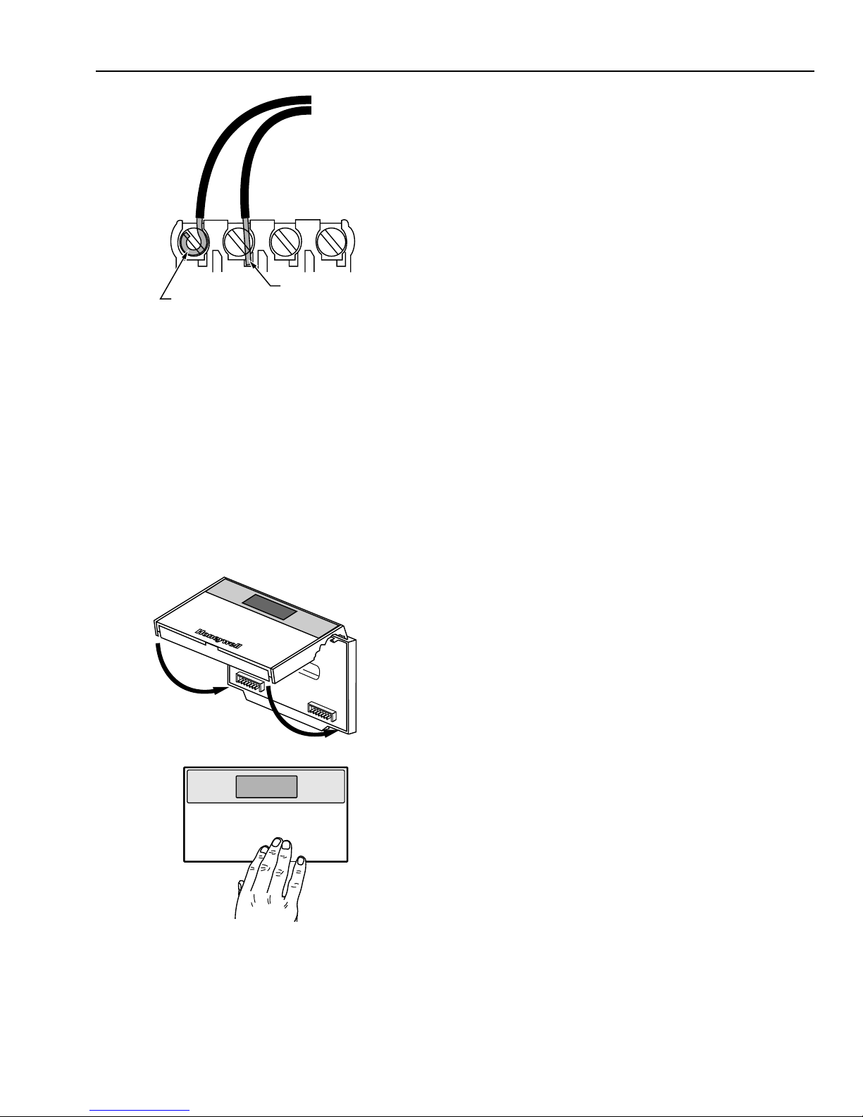
1. Loosen the terminal screws on the subbase or wallplate
and connect the system wires. See Fig. 9.
IMPORTANT
Use 18-gauge, solid-conductor color-coded
thermostat cable for proper wiring. If using
18- gauge stranded wire, no more than ten wires
can be used. Do not use larger than 18-gauge wire.
63-4355—2 8
2. Securely tighten each terminal screw.
3. Push excess wire back into the hole.
4. Plug the hole with nonflammable insulation to prevent
drafts from affecting the thermostat.
T7200D ,E, T7300D,E,F AND Q7300 SERIES 2000 PROGRAMMABLE COMMERCIAL THERMOSTATS AND SUBBASES
SETTINGS
Using Thermostat Keys
The thermostat keys are used to:
• set current time and day,
• program times and setpoints for heating and cooling,
• override the program temperatures,
• display present setting,
• set system and fan operation,
• configure Installer Setup,
• check Installer System Test.
FOR STRAIGHT
FOR WRAPAROUND
INSERTION STRIP
7/16 IN. (11 MM).
Fig. 9. Proper wiring technique.
INSERTION STRIP
5/16 IN. (8 MM).
M4826
Mounting Thermostat on Subbase or
Wallplate
The thermostat mounts on the subbase or wallplate after they
are installed.
1. Engage the tabs at the top of the thermostat and
subbase or wallplate. See Fig. 10.
2. Press the lower edge of the case to latch.
NOTE: To remove the thermostat from the wall, first pull out
at the bottom of the thermostat; then remove the top.
A. ENGAGE TABS AT TOP OF THERMOSTAT AND SUBBASE OR WALLPLATE.
See Fig. 11 for key information.
Setting System and Fan (select models)
The system default setting is Heat. The fan default is set so
the fan operates continuously in Occupied periods,
Unoccupied period recovery times and with the heating and
cooling equipment in Unoccupied periods. Use the System
and Fan keys to change the settings. Fan and system
operation are configured in the Installer Setup options.
The system settings are:
Em Heat (T7200E, T7300/Q7300C,D,H): Emergency heat
relay is on continuously. Thermostat cycles highest stage
of heat. Cooling system is off. Compressor is de-energized.
Heat: Thermostat controls the heating.
Off: Both the heating and cooling are off.
Cool: Thermostat controls the cooling.
Auto: Thermostat automatically changes between heating
and cooling depending on the indoor temperature.
The fan settings are:
On: Fan operates continuously in occupied period.
Auto: Equipment controls the fan in the Unoccupied
periods. The Intelligent Fan™ operation (Installer Setup
number 17) offers three choices for the fan operation in
Occupied periods:
— fan turns on only when there is a call for heating or
cooling.
— fan operates continuously in Occupied periods.
— fan is on continuously in Occupied periods and
Unoccupied period recovery times.
B. PRESS LOWER EDGE OF CASE TO LATCH.
Fig. 10. Mounting thermostat on subbase or wallplate.
Setting Temperature
Refer to Table 7 for the default temperature setpoints. See
Programming section for complete instructions on changing
the setpoints.
M4824A
63-4355—29

T7200D ,E, T7300D,E,F AND Q7300 SERIES 2000 PROGRAMMABLE COMMERCIAL THERMOSTATS AND SUBBASES
ENTER OCCUPIED
PROGRAM MODE
RETURNS TO
NORMAL
OPERATIONS
SET OVERRIDE
TEMPERATURE
OFFSET AND
ACTIVATE
TEMPORARY
OVERRIDE
ENTER HOLD MODE
Run
Program
Temporary
Occupied
Continuous
Unoccupied
SET CURRENT
DAY AND TIME
CLEAR PROGRAM PERIOD
Fig. 11. Thermostat key locations and descriptions.
ENTER UNOCCUPIED
PROGRAM MODE
SET CURRENT DAY OR
PROGRAM DAY
AM
Mon
Occupied
System Fan
Heat
Set Program Set Temperature Change
Occupied
Start Time
Set Current
Day/Time
Unoccupied
Start Time Day
Clear
Start Time
Copy
COPY ONE
PROGRAMMED DAY
TO ANOTHER DAY
SET OCCUPIED
TEMPERATURE
SETPOINTS
Room
Auto
Occupied
Temp
System Fan
SELECT
SYSTEM
OPERATION
Unoccupied
Temp
Heat/Cool
Settings
Time/Temp
SELECT FAN
OPERATION
SET UNOCCUPIED TEMPERATURE
SETPOINTS AND SCROLLS
THROUGH INSTALLER SETUP
AND SYSTEM TEST
INCREASE
TEMPERATURE
OR TIME SETTING
DECREASE
TEMPERATURE
OR TIME SETTING
CHANGE BETWEEN HEATING
AND COOLING SETPOINTS
AND SCROLLS BACKWARDS
THROUGH INSTALLER SETUP
NUMBERS AND SYSTEM TEST
M10233A
Table 7. Default Temperature Setpoints.
Control Occupied Unoccupied
Heating 70°F (20°C) 55°F (13°C)
Cooling 78°F (25.5°C) 90°F (32°C)
INSTALLER SETUP
NOTE: For most applications, the thermostat factory
settings do not need to be changed. Review the
factory settings in Table 8 and if no changes are
necessary, go to the Installer System Test section.
The Installer Setup is used by the installer to customize the
thermostat to specific systems. Installer Setups are listed in
Table 8. The table includes all the configuration options
available.
A combination of key presses are required to use the Installer
Setup feature.
— To enter the Installer Setup, press and hold the Heat/Cool
Settings key and both the increase ▲ ▲ and ▼ ▼ decrease
keys until the first number is displa yed. All display
segments appear for approximately three seconds before
the number is displayed. See Fig. 12 and 13.
Set Program
Start Time
Em Ht
Aux Ht
Comm
Mon
TueWedThuFriSatSun
Un
Occupied 12 Override
Set Day/Time
AM
PM
System Fan
Cool
Off Auto
Heat
Em
Temporary Setting Enrg
Heat
Recovery
In
Lo
Med
Hi
Wait
Cool
Auto
Room
%Humid
Remote
Only
On
Sav
Duct
Auto
M4916
Fig. 12. LED display of all segments.
MODE NUMBER
DISPLAY
(COLUMN 2
OF TABLE 8)
FACTORY SETTING
OR OTHER CHOICE
DISPLAY (COLUMN 3
OR 5 OF TABLE 8)
M10227
Fig. 13. Installer Setup number and setting display.
63-4355—2 10
T7200D ,E, T7300D,E,F AND Q7300 SERIES 2000 PROGRAMMABLE COMMERCIAL THERMOSTATS AND SUBBASES
— To advance to the next Installer Setup number, press the
Unoccupied T emp ke y .
— To return to an Installer Setup number, press the Heat/
Cool Settings key.
— To change a setting, use the increase ▲ ▲ or ▼ ▼ decrease
key.
— To exit the Installer Setup, press the Run Program key.
The Installer Setup is automatically exited if no key
presses are made for four minutes.
CAUTION
Possible Equipment Damage.
Fan must be running when system is operating.
Heat pump and electric heat systems must be
configured correctly in Installer Setup 2 to prevent
equipment damage caused by the system running
without the fan.
NOTE: Be sure to set the thermostat time after exiting the
Installer Setup.
Installer Setup numbers are listed in Table 8.
IMPORTANT
Only configurable numbers are shown on the device.
Example: If the thermostat does not have a system
key, Installer Setup number 12 will not be displayed.
Review Table 8 factory settings and mark any
desired changes in the Actual Setting column. When
the Installer Setup is complete, review the settings to
confirm that they match the system.
Table 8. Thermostat Installer Setup Options.
Installer
Setup Number
(Press
Unoccupied
Temp key
a
to change)
2 0 Conventional
3 Depends
4 4 Stage 1—4 cph. 3, 6, 8 or
5 4 Stage 2—4 cph.
6 4 Stage 3—4 cph.
7 4 Emergency heat relay
8 Depends
9 4 Stage 1—4 cph. 3 3—3 cph.
10 4 Stage 2—4 cph.
11 4 Stage 3—4 cph.
12 Depends
14 0 Temperature is
Display Description Display Description
subbase
subbase
on model
Select
Not used 1 — — — — —
Fan operation
Output stages
of heating
Heating cycle
rate
Output stages
of cooling
Cooling cycle
rate
System setting
adjustment
(models with
System key)
Not used 13 — — — — —
Degree
temperature
display
a
Number 2 must be set to 1 to extend fan operation.
Factory Setting
applications where
equipment controls fan
operation in heat mode.
Stages of heat. 0, 1, 2,
on
is on continuously.
Highest stage of heat
cycles at 4 cph
(Q7300C or D only).
Stages of cooling. 0, 1, 2
on
System selection. 0, 1 or 2 0—System setting key is
displayed in °F.
(Press ▲ or ▼ key to change)
1 Electric heat applications where
or 3
9
or 3
1 Temperature is displayed in °C.
Other Choices
Actual
Setting
thermostat controls fan operation in
heat mode.
0—No heating.
1—One stage of heat.
2—Two stages of heat.
3—Three stages of heat.
3—3 cph used for hot water
systems or high efficiency
furnaces.
6—6 cph used for conventional
systems.
8—8 cph used for conventional
systems.
9—9 cph used for electric heat
systems.
0—No cooling.
1—One stage of cool.
2—Two stages of cool.
3—Three stages of cool.
operational.
1—Auto setting is disabled.
2—Auto only setting.
(continued)
63-4355—211
T7200D ,E, T7300D,E,F AND Q7300 SERIES 2000 PROGRAMMABLE COMMERCIAL THERMOSTATS AND SUBBASES
Table 8. Thermostat Installer Setup Options
(Continued).
Installer
Setup Number
Select
Displaying
temperature
(Press
Unoccupied
Temp key
to change)
Display Description Display Description
Factory Setting
15 0 Temperature is
displayed.
(Press ▲ or ▼ key to change)
1 Temperature is not displayed.
Other Choices
Actual
Setting
(T7300F only).
Clock format. 16 0 12-hour clock format. 1 24-hour clock format.
Intelligent Fan™
operation.
17 2 Fan operates con-
tinuously in Occupied
and recovery modes.
Fan operates with call
for heating or cooling in
Unoccupied mode.
0 or 1 0—Fan only operates with calls for
heating or cooling in Occupied
and Unoccupied modes.
1—Fan operates continuously in
Occupied mode. Fan operates
with calls for heating or cooling
in Unoccupied mode.
Auxiliary contact
operation.
Extended fan
operation in
a
heating
18 0 0—Time of day
contact.
19 0 No extended fan
operation after the call
for heat ends.
0 or 1 1—Economizer contacts. —
1 Fan operation is extended
90 seconds after the call for
heat ends.
(T7300F only).
Extended fan
operation in
cooling (T7300
20 0 No extended fan
operation after the call
for cool ends.
1 Fan operation is extended
90 seconds after the call for
cool ends.
only).
Fan key adjust-
ment (models
21 0 Fan setting key is
operational.
1 Fan setting key is Auto only.
with Fan key).
Remote sensing. 22 0 Remote sensing not
1 Remote sensing activated.
activated.
Temperature
averaging
network
b
(T7300
23 0 Temperature averaging
disabled.
1 Temperature averaging between
local sensor and remote sensor(s)
activated.
only).
Not used. 24 — — — — —
Keypad lockout
level (keypad
lockout is
enabled and
disabled by DIP
switch 1 on
back of
thermostat).
25 0 No lockout. 1 or 2 1—Lockout all keys on thermostat
except system and fan settings,
temporary setpoint, clock and
day adjustments, increase ▲ and
▼ decrease keys.
2— Lockout all keys except Set
Current Day/Time, increase ▲
and decrease ▼ keys.
3—Lockout all keys except
Temporary Occupied and Set
Current Day/Time (for clock, day
adjustment).
Duration of
temporary
override.
26 3 3—Three hour
override.
1, 8 or 12 1—One hour override.
8—Eight hour override.
12—Twelve hour override.
Not used. 27 thru 29 — — — — —
Deadband
(T7300F only).
b
Number 22 must be set to 1 and remote sensor(s) must be installed.
30 2 Heating and cooling
setpoints can be set no
closer than 2°F (1.1°C).
3 thru 10 Heating and cooling setpoints can
be set no closer than the chosen
value.
(continued)
63-4355—2 12
 Loading...