

Page 1
PolyGard is a registered trademark of MSR GAMGC2-K_E_0320
Phone 0049(0)8531/9004-0 Fax: 0049(0)8531/9004-54 Specification subject to change without notice
MSR-Electronic GmbH, Bgm.-Schoenbauer-Str. 13, D 94060 Pocking www:msr-electronic.de Made in Germany
PolyGard2 Multi Gas Controller MGC2-K
Controller for Analog Sensors / Honeywell Sensors
User Manual
Version 26.03 2020 en
Page 2

User Manual - PolyGard®2
Multi-Gas-Controller MGC2-K Honeywell
Page 2
PolyGard® is a registered trademark of MSR GAMGC2-K_E_0320
Phone 0049(0)8531/9004-0 Fax: 0049(0)8531/9004-54 Specification subject to change without notice
MSR-Electronic GmbH, Bgm.-Schoenbauer-Str. 13, D 94060 Pocking www:msr-electronic.de Made in Germany
1 Intended Use .......................................................................................................... 4
2 Functional Description ......................................................................................... 4
2.1 General ................................................................................................................................... 4
3 Installation ............................................................................................................. 5
3.1 Mounting Instructions .............................................................................................................. 5
3.2 Installation Work ..................................................................................................................... 5
4 Electrical Connection ........................................................................................... 6
4.1 Wiring ...................................................................................................................................... 6
4.2 Wiring Diagrams ..................................................................................................................... 7
5 Intended Use for the Display Unit ........................................................................ 8
6 Description ............................................................................................................ 8
7 Operation ............................................................................................................... 8
7.1 Function of the Keys and LEDs on the Keypad ...................................................................... 8
7.2 Setting / Changing of Parameters and Set Points .................................................................. 9
7.3 Code Levels ............................................................................................................................ 9
8 Menu Overview .................................................................................................... 10
8.1 Fault Management ................................................................................................................ 12
8.1.1 Error Memory .................................................................................................................... 12
8.1.2 System Messages and System Errors .............................................................................. 12
8.2 Alarm Status ......................................................................................................................... 13
8.3 Relay Status .......................................................................................................................... 13
8.4 Menu Measuring Values ....................................................................................................... 14
8.5 Display Parameters .............................................................................................................. 14
8.5.1 Software Version ............................................................................................................... 14
8.5.2 Language .......................................................................................................................... 15
8.5.3 Service Phone Number ..................................................................................................... 15
8.5.4 Customer Password .......................................................................................................... 15
8.5.5 Error Time Delay ............................................................................................................... 15
8.5.6 LCD Function .................................................................................................................... 16
8.6 Menu Relay Parameters ....................................................................................................... 16
8.6.1 Relay Mode ....................................................................................................................... 16
8.6.2 Relay Operation Mode ...................................................................................................... 16
8.6.3 Relay Function Static / Flashing........................................................................................ 17
8.6.4 Alarm Quantity................................................................................................................... 17
8.6.5 Horn Function .................................................................................................................... 17
8.6.6 External Override .............................................................................................................. 18
8.6.7 Delay Mode of Alarm Relay .............................................................................................. 19
8.6.8 Assignment to Fault .......................................................................................................... 19
8.6.9 Assignment to Maintenance Message .............................................................................. 19
8.7 MP Parameters ..................................................................................................................... 20
8.7.1 Activate – Deactivate MP .................................................................................................. 20
8.7.2 Selection of Gas Type and Measuring Range .................................................................. 20
8.7.3 Alarm Thresholds / Hysteresis .......................................................................................... 23
8.7.4 Delay for Alarm ON and/or OFF........................................................................................ 24
8.7.5 Average Overlay ............................................................................................................... 24
8.7.6 Latching Mode Assigned to Alarm .................................................................................... 24
8.7.7 MP Fault Assigned to Alarm .............................................................................................. 25
Page 3

User Manual - PolyGard®2
Multi-Gas-Controller MGC2-K Honeywell
Page 3
PolyGard® is a registered trademark of MSR GAMGC2-K_E_0320
Phone 0049(0)8531/9004-0 Fax: 0049(0)8531/9004-54 Specification subject to change without notice
MSR-Electronic GmbH, Bgm.-Schoenbauer-Str. 13, D 94060 Pocking www:msr-electronic.de Made in Germany
8.7.8 Alarm Assigned to Alarm Relay ........................................................................................ 25
8.7.9 MP Assigned to Analog Output ......................................................................................... 25
8.8 Menu System Parameters .................................................................................................... 26
8.8.1 System Information ........................................................................................................... 26
8.8.2 Maintenance Interval ......................................................................................................... 26
8.8.3 Average Function .............................................................................................................. 26
8.8.4 Power On Time ................................................................................................................. 27
8.8.5 Deadband .......................................................................................................................... 27
8.8.6 AO Function ...................................................................................................................... 28
8.8.7 Relay Multiplication ........................................................................................................... 29
8.9 Operating Data...................................................................................................................... 30
8.10 Test Function for Relays ....................................................................................................... 31
8.11 Test Function for Analog Output ........................................................................................... 32
8.12 Calibration ............................................................................................................................. 33
8.12.1 Zero Calibration of Analog Output..................................................................................... 34
8.12.2 Calibration of the Digital Sensors ...................................................................................... 34
8.12.3 Credit Menu ....................................................................................................................... 34
8.13 Setting RS-485 Address ....................................................................................................... 34
9 Commissioning ................................................................................................... 35
9.1 General Notes ....................................................................................................................... 35
9.2 Visual Inspection ................................................................................................................... 35
9.3 Selection Gas Type with Unit ................................................................................................ 35
10 Configuration and Parameter Cards .................................................................. 36
10.1 Configuration Card System Parameters ............................................................................... 36
10.2 Configuration Card Alarm Relays / Signal Outputs .............................................................. 36
10.3 Configuration Card MC2 of Analog Measuring Points .......................................................... 37
11 Routine Maintenance and Scheduled Testing .................................................. 38
11.1 Routine Maintenance ............................................................................................................ 38
11.2 Routine Testing ..................................................................................................................... 38
12 Technical Data MGC2 ......................................................................................... 39
13 EC – Declaration of Conformity ......................................................................... 40
14 Part Disposal ....................................................................................................... 41
15 Notes and General Information .......................................................................... 41
15.1 Installers’ Responsibilities ..................................................................................................... 41
15.2 Disclaimer ............................................................................................................................. 41
15.3 Warranty ............................................................................................................................... 42
15.4 Copyright Notice ................................................................................................................... 42
Page 4

User Manual - PolyGard®2
Multi-Gas-Controller MGC2-K Honeywell
Page 4
PolyGard® is a registered trademark of MSR GAMGC2-K_E_0320
Phone 0049(0)8531/9004-0 Fax: 0049(0)8531/9004-54 Specification subject to change without notice
MSR-Electronic GmbH, Bgm.-Schoenbauer-Str. 13, D 94060 Pocking www:msr-electronic.de Made in Germany
1 Intended Use
The PolyGard2 MGC2 is designed for detection and warning detection of toxic, combustible or dangerous
atmosphere in many commercial and industrial applications.
The intended sites are all areas being directly connected to the public low voltage supply, e.g. residential,
commercial and industrial ranges as well as small enterprises (according to EN50 082).
The PolyGard2 Multi Gas Controller MGC2 must not be used in potentially explosive atmospheres. The
sensor must only be employed in areas within the environmental conditions specified in the Technical Data.
2 Functional Description
2.1 General
The Multi-Gas-Controller is designed for the connection of max. three analog sensors with 4-20 mA signal and
eight Honeywell sensors.
The controller monitors the measured values and activates the alarm relays if the set local alarm thresholds for
pre-alarm and main alert have been exceeded or if there are the alarm messages coming from the eight digital
sensors via RS-485 communication.
The SIL 2 compliant self-monitoring function in the MGC2 activates the fault message in case of an internal
error as well as in case of a fault at the 4-20 mA input / output current signals or if there is a communication
error to the digital sensors.
Other options such as three-color status LED, warning buzzer, digital input for acknowledgment or test function
ensure proper adaptation to the wide range of applications in gas detection technology.
Page 5
User Manual - PolyGard®2
Multi-Gas-Controller MGC2-K Honeywell
Page 5
PolyGard® is a registered trademark of MSR GAMGC2-K_E_0320
Phone 0049(0)8531/9004-0 Fax: 0049(0)8531/9004-54 Specification subject to change without notice
MSR-Electronic GmbH, Bgm.-Schoenbauer-Str. 13, D 94060 Pocking www:msr-electronic.de Made in Germany
3 Installation
Electronics can be destroyed by electrostatic discharge (ESD). Therefore, the installation work
should be done only by persons connected to ground, e. g. with a wrist strap connected to ground
or by standing on a conductive floor (acc. to DIN EN 100015).
3.1 Mounting Instructions
When choosing the mounting site please pay attention to the following:
• Choose mounting location of the sensor according to the local regulations.
• Mount the sensor at a location with minimum vibration and minimum variation in temperature (avoid
direct sunlight).
• Avoid locations where water, oil etc. may influence proper operation and where mechanical damage
might be possible.
• Provide adequate space around the sensor for maintenance and calibration work.
• Observe possible local instructions.
3.2 Installation Work
Assembly work must only be carried out under gas-free conditions.
Do not drill holes in the housing. Use only the providing know-outs.
• Open housing cover.
• Break out the required pre-embossed knockouts on the housing for cable glands and Sensor
Cartridge.
• Cables are introduced from above.
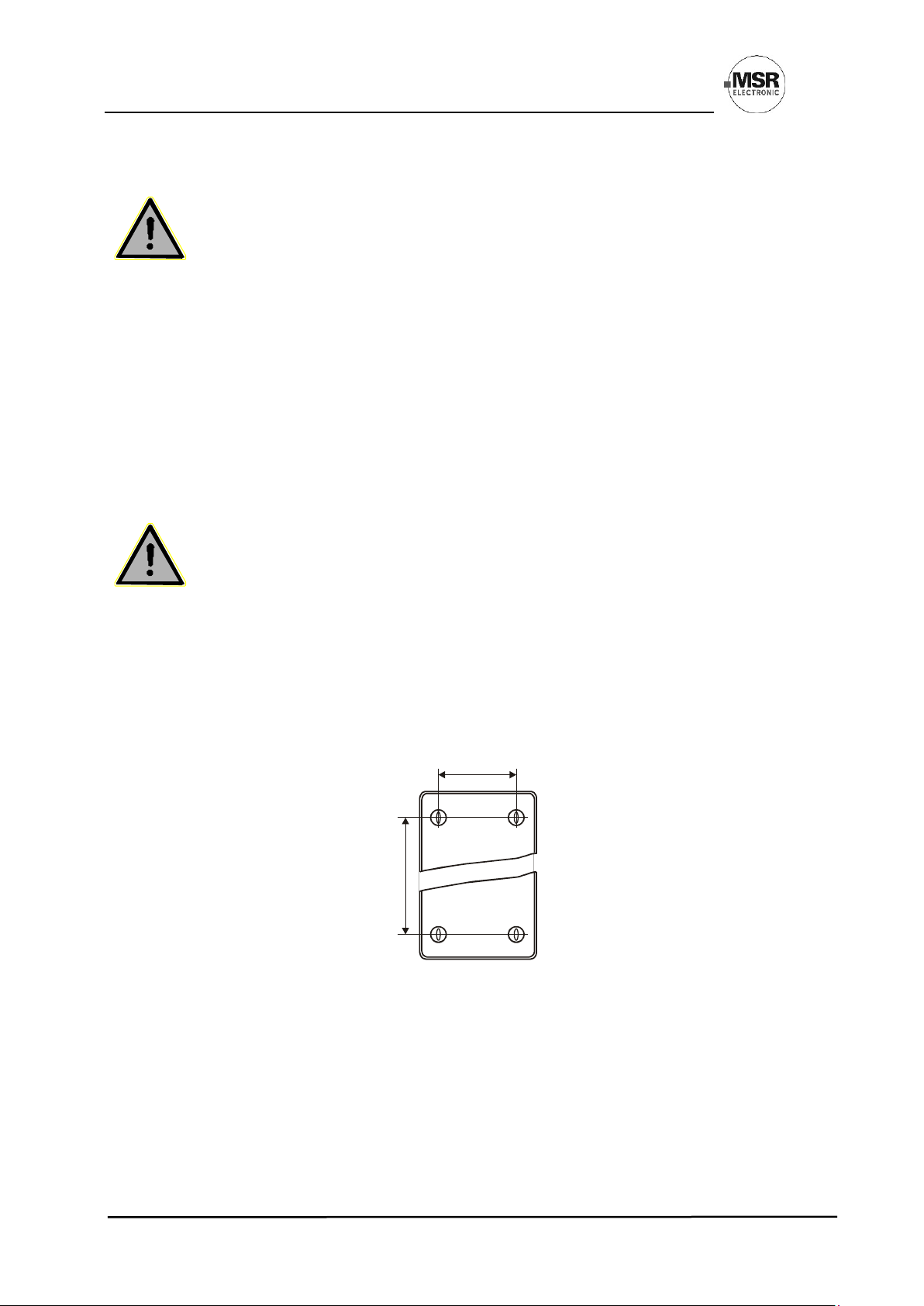
• The MGC2 Controller is fixed to the wall through the four marked mounting points at the back side of
the housing. These mounting points are accessible after opening the housing. See figure below.
• The dimensions XX depend on the type and can be read on the back of the housing, it is115 mm.
• The mounting points are covered by closing the cover at the end of the assembly.
• Close the cover.
Installation of Controller:
XX
XX
Page 6

User Manual - PolyGard®2
Multi-Gas-Controller MGC2-K Honeywell
Page 6
PolyGard® is a registered trademark of MSR GAMGC2-K_E_0320
Phone 0049(0)8531/9004-0 Fax: 0049(0)8531/9004-54 Specification subject to change without notice
MSR-Electronic GmbH, Bgm.-Schoenbauer-Str. 13, D 94060 Pocking www:msr-electronic.de Made in Germany
4 Electrical Connection
Assembly work must only be carried out under gas-free conditions!
Consider static electricity instructions (ESD)!
4.1 Wiring
• The technical requirements and regulations for wiring, electrical safety, as well as project specific and
environmental and local conditions etc. must be observed when mounting.
• We recommend the following cable types1:
Europe USA / Canada
Power supply 230 V NYM-J 3 x 1.5 mm
2
14 AWG / 300 V
Alarm message 230 V (also possible together with power supply) NYM-J X x 1.5 mm
2
14 AWG / 300 V
Signal message, bus connection, warning devices 24 V J-Y(St)Y 2x2 x 0.8 mm2 min. 300 V
Possibly connected external analog transmitters J-Y(St)Y 2x2 x 0.8 mm
2
min. 300 V
1
The recommendation does not consider local conditions such as fire protection etc.
• Use copper conductors only for the terminal is only for connection to copper wire.
• Avoid any influence of external interferences by using shielded cables for the bus line, but do not
connect the shield.
• Remove the cable isolation as short as possible. It is important to ensure that bare wires, e.g. wire
shields do not come into contact with the mounted PCB (risk of short-circuit).
• Low voltage wire and mains connected wire must be fixed separately by cable ties or similar, to secure
against looseness.
• Analog sensors are connected directly to the spring type terminals of the module. The correct polarity
must be observed.
• The alarm signals are available as voltage-free change-over contacts. If required, the voltage supply is
available at the terminal L.
The exact position of the terminals for the sensors and alarm relays is shown in the connection diagrams.
Page 7
User Manual - PolyGard®2
Multi-Gas-Controller MGC2-K Honeywell
Page 7
PolyGard® is a registered trademark of MSR GAMGC2-K_E_0320
Phone 0049(0)8531/9004-0 Fax: 0049(0)8531/9004-54 Specification subject to change without notice
MSR-Electronic GmbH, Bgm.-Schoenbauer-Str. 13, D 94060 Pocking www:msr-electronic.de Made in Germany
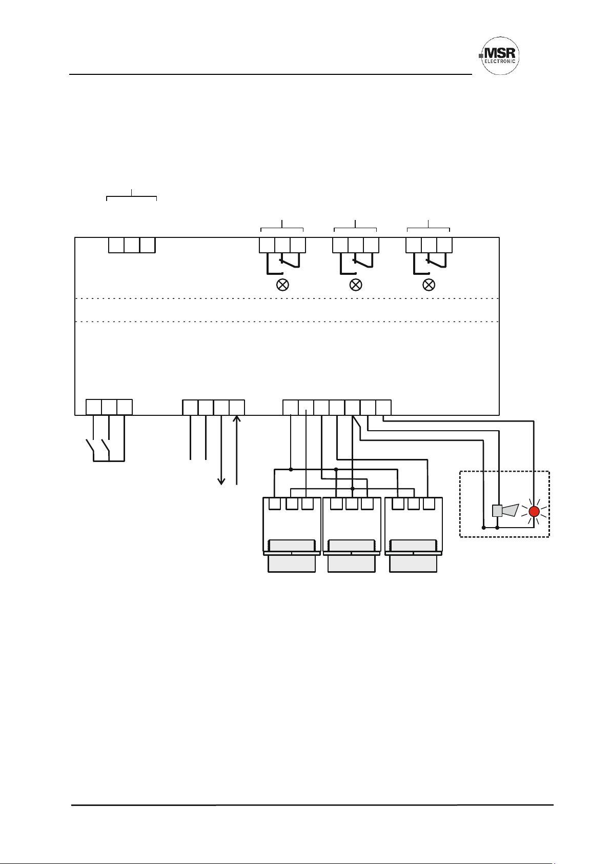
4.2 Wiring Diagrams
Wiring Diagram Example
+24 V
GND
NC
X2 X3 X41 1 12 2 23 3 3
Multi Gas Controller MGC2 24 VDC
Bus_A
Bus_B
4 - 20 mA
GND
Field Bus Analog
Input
Digital
Output
1 13 32 24 4 5 6 7
X12
X13
BUS_A
24 VDC
AI_01
AI_02
AI_03
GND
Beacon
Horn
AO_01
BUS_B
GND
Analog
Output
24 VDC
24 VDC
24 VDC
GND
GND
GND
4-20mA
4-20mA
4-20mA
1 1 12 2 23 3 3
X1 23 1
Power Supply
24 VDC
Relay
Alarm 1
Relay
Alarm 2
Relay
Fault
Relay Voltage
Max. 230
Relay drawn de-energized
Relays Mode = Energized (Alarm ON = Relay OFF)
Digital
Input
DI_1
DI_2
1 2 3
Digital
Input
GND
X11
Page 8
User Manual - PolyGard®2
Multi-Gas-Controller MGC2-K Honeywell
Page 8
PolyGard® is a registered trademark of MSR GAMGC2-K_E_0320
Phone 0049(0)8531/9004-0 Fax: 0049(0)8531/9004-54 Specification subject to change without notice
MSR-Electronic GmbH, Bgm.-Schoenbauer-Str. 13, D 94060 Pocking www:msr-electronic.de Made in Germany
Display Unit for Series MGC2-K
5 Intended Use for the Display Unit
The display is used as visual indication, operating, commissioning and calibration unit for gas detecting and
measuring instruments of the series PolyGard®2 (PG2).
6 Description
The parameters, gas types, units, etc. specified in the description are only examples.
7 Operation
The complete configuration and service are made via operating keys in combination with the LCD display
screen. Security is provided via four password levels against unauthorized intervention
Version for PG2 series
Operation via 6 buttons
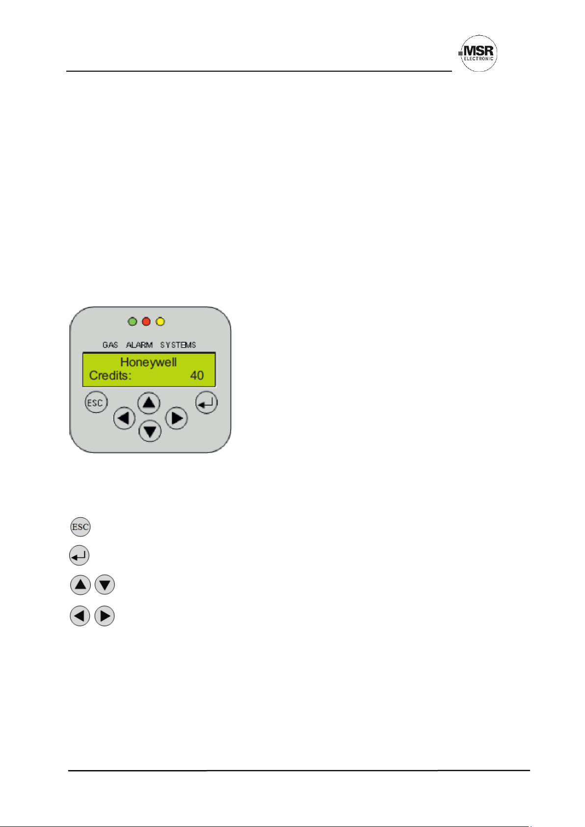
7.1 Function of the Keys and LEDs on the Keypad
Exits programming, returns to the previous menu level.
Enters sub menus, saves parameter settings.
Scrolls up & down within a menu, changes a value.
Changes cursor position.
The status LEDs indicate the operating state.
Green: Continuous: = Normal operation
Flashing: = Maintenance message
Yellow: Continuous: = Failure
Slowly flashing: = Warming-up
Fast flashing: = Special mode
Red: =Alarm
The backlight of the display changes from green to red when an alarm is active.
Page 9

User Manual - PolyGard®2
Multi-Gas-Controller MGC2-K Honeywell
Page 9
PolyGard® is a registered trademark of MSR GAMGC2-K_E_0320
Phone 0049(0)8531/9004-0 Fax: 0049(0)8531/9004-54 Specification subject to change without notice
MSR-Electronic GmbH, Bgm.-Schoenbauer-Str. 13, D 94060 Pocking www:msr-electronic.de Made in Germany
7.2 Setting / Changing of Parameters and Set Points
Open desired menu window.
Code input field opens automatically, if required.
After input of valid code, the cursor jumps onto the first position segment to be changed.
Push the cursor onto the position segment, which has to be changed.
Set the desired parameter / set point with the keys.
Input of value finished.
Change further parameters in the same menu.
Save the changed value?
YES, and back to higher menu level.
NO, (previous value isn’t overwritten) and back to higher menu level.
7.3 Code Levels
All inputs and changes are protected by a four-digit numeric code (= password) against unauthorized
intervention according to the regulations of all national and international standards for gas warning systems.
The menu windows of status messages and measuring values are visible without entering a code.
The access to a code level is cancelled if no button is pushed within 15 minutes or if there is no data
communication between display and basic board.
The code levels are classified in order of priority: Priority 1 has top priority.
Priority 1: (code not changeable)
Code level priority 1 is intended for the service technician of the installer to change parameters and set-points.
This password allows working on all settings. For opening the parameter menus, you must first activate the
service mode after code release.
Priority 2: (code not changeable)
This functionality isn’t available.
Priority 3: (customer password is settable)
Customer password is inactive in delivery state and is activated by entering a value. Same behaviour as priority
1 password, only changing the customer password is not possible.
Normally the code is only known by the service technician who has last changed it since it can be changed
individually via priority 1.
Priority 4: (password 1234) (code not changeable)
Code level priority 4 allows the operator after activation of the operation mode “Service Mode” to read all
parameters as well as all test functions of the alarm relays, analog outputs and LCD.
- Manual test function of the alarm relays (functional test of the connected actuators),
- Manual test function of the analog outputs (functional test of the connected actuators),
- Manual test function of the LCD (functional test of the LCD display and the LEDs).
Page 10
User Manual - PolyGard®2
Multi-Gas-Controller MGC2-K Honeywell
Page 10
PolyGard® is a registered trademark of MSR GAMGC2-K_E_0320
Phone 0049(0)8531/9004-0 Fax: 0049(0)8531/9004-54 Specification subject to change without notice
MSR-Electronic GmbH, Bgm.-Schoenbauer-Str. 13, D 94060 Pocking www:msr-electronic.de Made in Germany
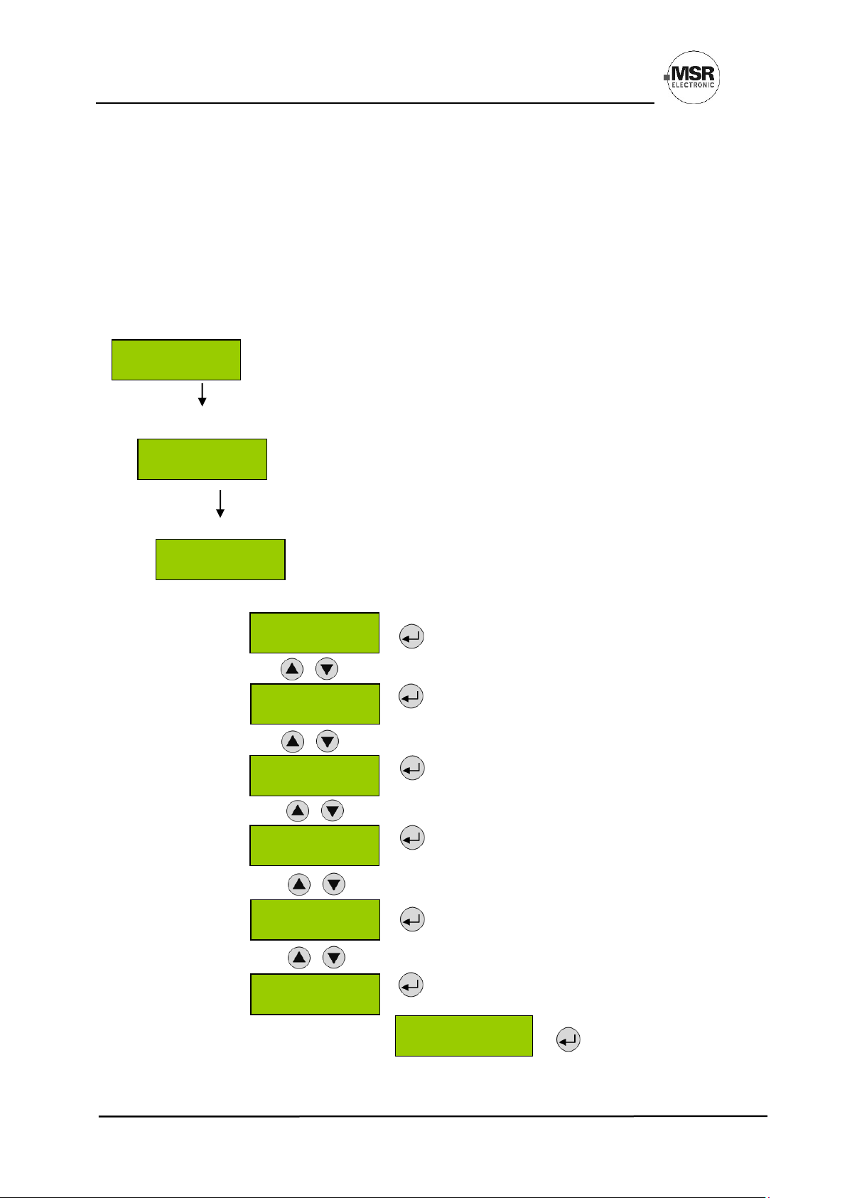
8 Menu Overview
Menu operation is done via a clear, intuitive and logical menu structure. The operating menu contains the
following levels:
• Starting menu with indication of the device type if no MP (Measuring Point) is registered. Otherwise
scrolling display of the gas concentrations of all registered sensors in 5-second intervals. If alarms are
active, only the values of the sensors currently in alarm status will be displayed.
• Main menu
• Submenu 1 to 3
Power On Time of the basic device
Second counter counts down, when communication between display <> basic
device is OK. In case of communication error, the count-down will stop.
Seconds indicator = 0
MGC2-K = Multi Gas Controller Kompakt
After about 5 seconds
“Warn-up Time” is displayed. As soon as the sensor warm-up period has
expired, the measured value is displayed = measuring mode.
Starting menu Main menu Submenu 1
Reading and acknowledgement of errors
See from point 8.1
Display of the alarm status of active alarms
See from point 8.2
Display of the relay status
See from point 8.3
Display of measuring values
See from point 8.4
General display parameters without safety relations
See from point 8.5
Reading and change of the relay, measuring point
and system parameters as well as test and calibration
functions
D1 CH4 % LEL
Warm-up Time
System Errors
Alarm Status
Relay
Status
Measuring Values
Display
Parameter
Power On Time
19s
Honeywell
MGC2-K
Installation &
Calibration
Service Mode
OFF
Page 11
User Manual - PolyGard®2
Multi-Gas-Controller MGC2-K Honeywell
Page 11
PolyGard® is a registered trademark of MSR GAMGC2-K_E_0320
Phone 0049(0)8531/9004-0 Fax: 0049(0)8531/9004-54 Specification subject to change without notice
MSR-Electronic GmbH, Bgm.-Schoenbauer-Str. 13, D 94060 Pocking www:msr-electronic.de Made in Germany
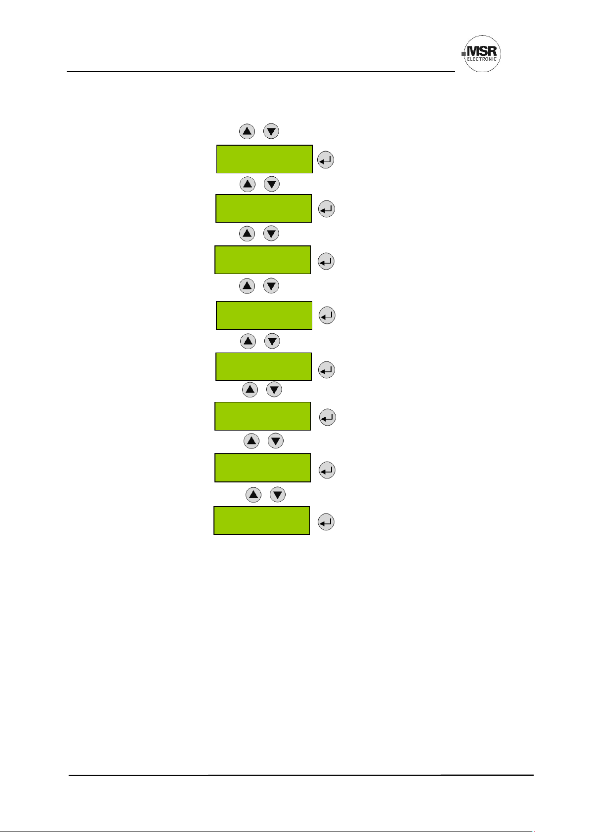
The following menu items are only accessible in Service ON mode (password protected)
!! Service ON = Special mode = Fault message is active!!
See from point 8.6
See from point 8.7
See from point 8.8
See from point 8.9
See from point 8.10
See from point 8.11
See from point 8.12
See from point 8.13
Relay Parameter
MP Parameter
System Parameter
Operating Data
Addressing
Calibration
Relay
Test Function
Analog Outputs
Test Function
Page 12
User Manual - PolyGard®2
Multi-Gas-Controller MGC2-K Honeywell
Page 12
PolyGard® is a registered trademark of MSR GAMGC2-K_E_0320
Phone 0049(0)8531/9004-0 Fax: 0049(0)8531/9004-54 Specification subject to change without notice
MSR-Electronic GmbH, Bgm.-Schoenbauer-Str. 13, D 94060 Pocking www:msr-electronic.de Made in Germany
MP 1 Comm.Error
1 1T 2h 6‘
8.1 Fault Management
A pending fault activates the yellow LED (Fault).
The integrated fault management records the first 50 occurred faults with time
stamps in the menu “System Errors”. The timestamp shows the days, hours and
minutes that have elapsed since the fault has occurred.
Additionally, a record of the faults occurs in the “Error memory”, which can only be read and deleted by the
service technician (code level 1 (3)).
8.1.1 Error Memory
The menu “Error Memory” in the main menu “System Errors” can only be opened via the code level priority 1.
In the error memory, the first 50 faults that have occurred and have already been acknowledged in the menu
“Error Status” are listed for the service technician in a power failure safe way.
Attention:
This memory should always be read during maintenance, relevant faults should be tracked and entered
in the service logbook, and finally the memory should be emptied.
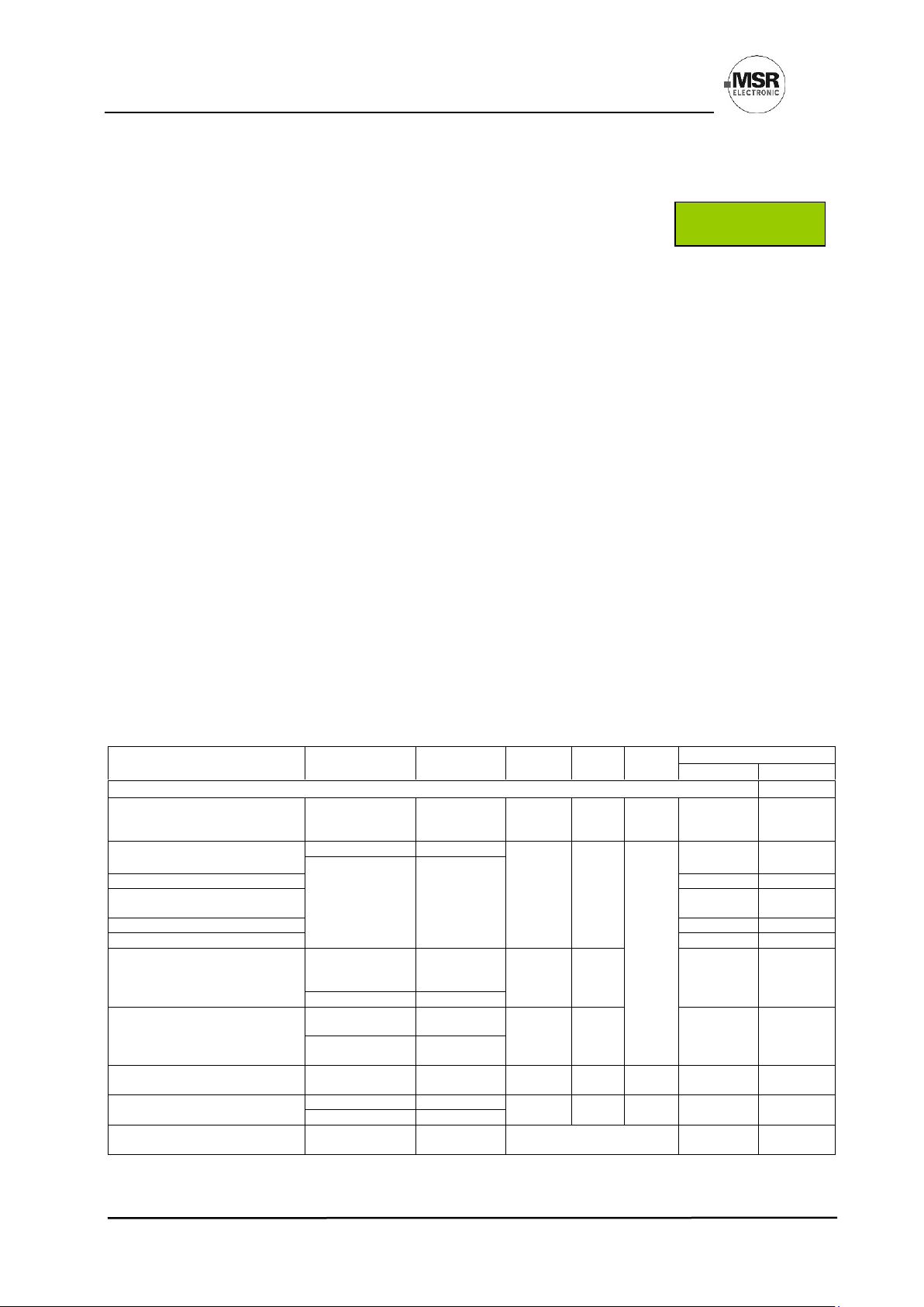
8.1.2 System Messages and System Errors
The warning device includes a diagnostic module for the continuous monitoring of the relevant functions and
parameters as well as a processor-independent watchdog. These features set the device into the safe mode
"Fault" in case of an internal or external error. The following table shows all possible errors, possible causes,
the related troubleshooting and the resulting device status.
Once the cause has been eliminated, the warning device restarts with the diagnostic mode on its own. It isn’t
necessary to acknowledge the error message. In the event of an error, the error is output as plain text in the
version with display instead of the measured value and in the Error status menu. In case of two or more errors,
the value is output with a cumulative, bit-coded error code.
Error Type
Cause
Remedy
Fault
Relay
Analog
Output
Centr.
Bus
Display
Error Code
Text Mess.
Error messages from MGC2
DP1-
Sensor element defective
Replace
sensor
Error
< 2 mA
Error
code is
sent
0x8 001 h
Sensor
Temperature < -25 °C > +60 °C
Ambient temp.
Temp.!
Error
< 2 mA
Error
code is
sent
0x8 002 h
Overtemp.
Internal
Replace device
Measured value processing
0x8 002 h
ADC error
RAM / ROM / µC error
0x8 008 h
CPU error
EEPROM error
0x8 010 h
EE error
No response alarm relay
0x8 020 h
I/O error
Deviation of analog output signal
< 5 % >
Short-circuit or
Interruption at the
analog output
Check wiring /
load
Error
X mA
0x8 020 h
I/O error
Internal
Replace device
Communication error to sensor
Sensor head not
fitted correctly
Check
Error
< 2 mA
0x9 000 h
Comm. error
Internal
Replace
Sensor
Hardware Watch Dog triggered
Internal, < system
voltage, µC defect.
Replace device
Error
< 1 mA
Comm.
STOP
Reset
Reset
Operating voltage limits exceeded
too high / too low
External
Check voltage
Error
< 2 mA
Comm.
STOP
0x8 008 h
Tension
Internal
Replace device
Maintenance due
Maintenance date
reached
Perform
maintenance
No effect
0x8 080 h*
Maintenance
Page 13
User Manual - PolyGard®2
Multi-Gas-Controller MGC2-K Honeywell
Page 13
PolyGard® is a registered trademark of MSR GAMGC2-K_E_0320
Phone 0049(0)8531/9004-0 Fax: 0049(0)8531/9004-54 Specification subject to change without notice
MSR-Electronic GmbH, Bgm.-Schoenbauer-Str. 13, D 94060 Pocking www:msr-electronic.de Made in Germany
AP 1
’’A1
AP 1
Reset?
Check if no
Gas present?
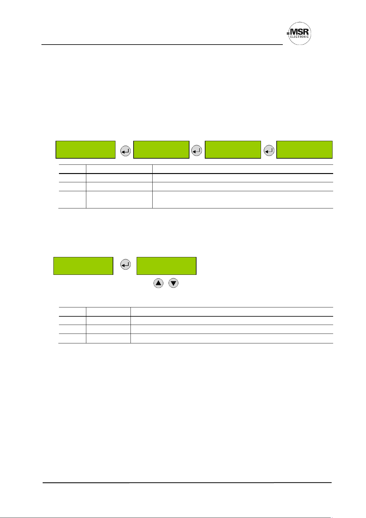
8.2 Alarm Status
Display of the currently pending alarms in plain text in the order of their arrival. Only those measuring points
are displayed, where at least one alarm is active.
Alarms in latching mode and the overrange message can be acknowledged in this menu (only possible if the
alarm isn’t active any more).
Alarm 1 and Alarm 2 are evaluated both by the sensor (alarm bit transmitted by communication) and by the
locally set thresholds.
Symbol
Description
Function
AP 1
Measuring Point No.
Analog measuring point 1 = 1 - 3, where an alarm is pending
DP 4
Measuring Point No.
Digital measuring point 4 = 4 - 11, where an alarm is pending
‘A1
‘‘A1
Alarm status
‘A1 = Alarm 1 active
‘‘A1 = Alarm 1 in latching mode, can be acknowledged
8.3 Relay Status
Reading of the current status of alarm relays.
The actual relay status is displayed, depending on the relay mode (energized <> de-energized).
Selection of the alarm relay 1 – 5
Selection of the next alarm relay
Symbol
Description
Function
1
Alarm Relay
Alarm relay = 1 - 5
OFF
Relay Status
Deenergized
ON
Relay Status
Energized
Alarm Status
Relay
Status
Relay 1
Status OFF
Page 14

User Manual - PolyGard®2
Multi-Gas-Controller MGC2-K Honeywell
Page 14
PolyGard® is a registered trademark of MSR GAMGC2-K_E_0320
Phone 0049(0)8531/9004-0 Fax: 0049(0)8531/9004-54 Specification subject to change without notice
MSR-Electronic GmbH, Bgm.-Schoenbauer-Str. 13, D 94060 Pocking www:msr-electronic.de Made in Germany
Measuring Values
D 4 CH4 % LEL
A ! 51.0 I
8.4 Menu Measuring Values
In this menu, the display shows the measuring value with gas type and unit. If the alarm evaluation is defined
via the average, the display additionally shows the average value (A) to the left of the current value (C).
Selection of the next measuring point
Symbol
Description
Function
A 11
Meas. Point No.
Analog measuring point 1 to 3
D 41
Meas. Point No.
Digital measuring point 4 to 11
CH4
Gas type
Display of gas type (must comply with gas type of sensor head)
% LEL
Gas unit
Unit (depending on gas type)
51,0 C
48,0 A
Measured value
C = Current measured value (current value) of the gas concentration
A = Arithmetic average of the gas concentr. (only if average is active)
A!
Alarm indication
At least one alarm has been released at this MP.
#
Maint. info
Sensor head: maintenance due (maintenance date exceeded)
Comm. err.
Fault MP
Communication error, sensor head <> I/O board
Underrange
Meas. range
monitoring
Meas. signal < admissible range (< zero point – 6 %)
Overrange2
Meas. signal > admissible range (> full scale value + 6 %)
Run-in
Run-in time
Warm-up of the sensor active
1
Display of the address number the measuring range is registered under in the Modbus
2
Acknowledgement in the menu Alarm Status
8.5 Display Parameters
In the menu Display Parameters, you can find the general, non-safety related parameters of the display. These
parameters can be changed in operating mode.
8.5.1 Software Version
Software version of the display and of the basic board
Symbol
Description
Function
XXXXX
YYYYY
Software Version of the displays
Software Version of the basic board
XXXXX Software Version
YYYYY Software Version
Software Version
XXXXX - YYYYY
Display
Parameters
Page 15

User Manual - PolyGard®2
Multi-Gas-Controller MGC2-K Honeywell
Page 15
PolyGard® is a registered trademark of MSR GAMGC2-K_E_0320
Phone 0049(0)8531/9004-0 Fax: 0049(0)8531/9004-54 Specification subject to change without notice
MSR-Electronic GmbH, Bgm.-Schoenbauer-Str. 13, D 94060 Pocking www:msr-electronic.de Made in Germany
Change Customer
Password ****
8.5.2 Language
Selection of the menu language (only code level 1 and 3)
Symbol
Description
Default
Function
English
Language
German
German
English
USA English
French
Italian
8.5.3 Service Phone Number
The service phone no. can be individually defined.
Symbol
Description
Default
Function
00800…
Phone No.
Definition of the individual service phone no.
8.5.4 Customer Password
Storage of an individual customer password on the display for changing the parameters. See 7.3 Code level
Priority 3. Changing the password only via access of the code level 1.
8.5.5 Error Time Delay
Symbol
Description
Default
Function
s
Delay
120s
Definition of a delay time after a communication error Display
<> Basic Board has occurred (only fault indication on the
display, no effect on the function or outputs)
Service TEL:
0080081819691
Error Delay
0s
Language
English
Page 16

User Manual - PolyGard®2
Multi-Gas-Controller MGC2-K Honeywell
Page 16
PolyGard® is a registered trademark of MSR GAMGC2-K_E_0320
Phone 0049(0)8531/9004-0 Fax: 0049(0)8531/9004-54 Specification subject to change without notice
MSR-Electronic GmbH, Bgm.-Schoenbauer-Str. 13, D 94060 Pocking www:msr-electronic.de Made in Germany
8.5.6 LCD Function
Testing the LCD hardware. Back-light is active for about 2 secs. The backlight is yellow. (Green and red are
activated at the same time). All segments are active on LCD.
The following area is only accessible if the service is set to "ON".
• With code priority 4 for reading the parameters
• With code priority 1 or 3 for changing the parameters.
8.6 Menu Relay Parameters
Reading and changing of the parameters separately for each alarm relay.
8.6.1 Relay Mode
Selection of alarm relay 1 - 5
The fault relay is listed as relay 3 and can be registered here as an
additional alarm relay. This registration has no influence on the
function as fault relay.
The relay switches off in addition when the assigned alarm is
active.
Symbol
Description
Default
Function
Used
Mode
Used
Used
Not Used
= Relay is registered and can be assigned to
an alarm
= Relay isn’t registered
8.6.2 Relay Operation Mode
Relay 3:
The parameter setting “Energized” cannot be changed.
The terms energized / de-energized come from the terms “energized / de-energized to trip” principle used for
safety circuits. The terms refer to the activation of the relay coil, not to the relay contacts (as they are executed
as changeover contacts and available in both principles).
The LEDs at the modules show the state in analogy. (LED off -> relay coil current-free)
Symbol
Description
Default
Function
Deenerg.
Mode
Deenerg.
De-energ.
Energ.
= Alarm OFF= Relay (and LED) current-free
Alarm ON = Relay (and LED) energized
= Alarm OFF = Relay (and LED) permanently energized
Alarm ON = Relay (and LED) current-free
Relay Mode
Used
Relay Parameters
Relay 1
Used
Operation Mode
Energized
LCD Function
check?
Installation &
Calibration
Service
OFF
Page 17

User Manual - PolyGard®2
Multi-Gas-Controller MGC2-K Honeywell
Page 17
PolyGard® is a registered trademark of MSR GAMGC2-K_E_0320
Phone 0049(0)8531/9004-0 Fax: 0049(0)8531/9004-54 Specification subject to change without notice
MSR-Electronic GmbH, Bgm.-Schoenbauer-Str. 13, D 94060 Pocking www:msr-electronic.de Made in Germany
8.6.3 Relay Function Static / Flashing
Relay 3:
The parameter setting “No” (cannot be changed).
The function "Flashing" offers a connection option for warning devices to improve visibility. The frequency is
about 1 second with an impulse / pause rate of 1:1.
If “Flashing” is set, the output circuit mustn’t be used as a safe output any more.
The combination of relay mode energized with flashing operation makes no sense and is therefore suppressed.
Symbol
Description
Default
Function
No
Function
No
Yes
No
= Relay function flashing in case of alarm
= Relay function static in case of alarm
8.6.4 Alarm Quantity
In some applications it is necessary that the relay switches only at the nth alarm. Here you can set the number
of active alarms necessary for relay tripping. For safety related applications, the relay must always switch on
the first alarm.
Symbol
Description
Default
Function
1
No. of Alarms
1
1 = Number of pending alarms for triggering the alarm relay
8.6.5 Horn Function
Relay 3:
The parameter setting cannot be changed.
The horn function of the alarm relay is activated if at least one of the two parameters (time or assignment to
digital input) is set. The horn function retains its functionality even for alarms in latching mode.
This feature is not allowed for safety-related alarm messages because the output is resettable.
Symbol
Description
Default
Function
Recurrence
Mode
No
No = Automatic reset of the relay after time has expired.
Yes = Recurrence function
Time
0
Enter time for automatic reset function or recurrence function in s
0 = No reset function
DI 0
0 – 2 = Assignment, which digital input resets the relay
Horn function resettable:
The activated horn can be reset with this function.
The following possibilities to acknowledge are available for the alarm relay as horn relay:
• By pressing the left button (ESC). Only available in starting menu.
• Automatic reset at the end of the preset time (active, if value > 0).
• By an external pushbutton (assignment of the appropriate digital input DI 1-n).
Due to fixed polling cycles, external buttons must be pressed for a few seconds before the reaction occurs.
Flashing
No
Time- Recurr.- DI
0s No 0
Alarm Quantity
1
Page 18

User Manual - PolyGard®2
Multi-Gas-Controller MGC2-K Honeywell
Page 18
PolyGard® is a registered trademark of MSR GAMGC2-K_E_0320
Phone 0049(0)8531/9004-0 Fax: 0049(0)8531/9004-54 Specification subject to change without notice
MSR-Electronic GmbH, Bgm.-Schoenbauer-Str. 13, D 94060 Pocking www:msr-electronic.de Made in Germany
After successful acknowledgment the horn remains permanently reset until all assigned alarms for this relay
function are inactive again. Only then it is triggered anew in case of an alarm.
Acknowledge the horn relay
Alarm 4
Relay 4
Gas concentration higher lower than threshold
Acknowledging
signal
On
Of
On
Off
On
Off
Time
Reset command by timer, external push-button or one of the operating keys.
Recurrence of the horn relay
After an alarm has been triggered, the horn will remain active until a reset action is done. After
acknowledgment of the horn relay (via a button or externally via digital input) a timer starts. When this time has
run out and the alarm is still acting, the relay is set again. This process is repeated endlessly as long as the
associated alarm remains active.
Alarm 4
Relay 4
Gas concentration higher lower than threshold
Acknowledging-
signal
On
Off
On
Off
On
Off
Time Time
Reset command by external push-button or one of the operating keys.
8.6.6 External Override
Relay 3:
The parameter setting cannot be changed.
Symbol
Description
Default
Function
DI 0
External ON
0
As long as DI 1-X is closed, relay switches ON
DI 0
External OFF
0
As long as DI 1- X is closed, relay switches OFF.
Manual operation of the alarm relays via DI does not start the "special mode", as this is a deliberate and
configured functionality. The use of the override should be used with caution, particularly the function "External
OFF".
Assignment of a digital input (DI) for the external alarm relay switching on/off.
This function has priority to gas alarm.
If External ON and External OFF are configured to the same relay and both are active at the same time, so in
this state, the External OFF command has priority. In this mode, too, the relay works respecting the parameter
settings "Static / Flashing" and "Energized / De-energized".
External function
DI 0 DI 0
Page 19

User Manual - PolyGard®2
Multi-Gas-Controller MGC2-K Honeywell
Page 19
PolyGard® is a registered trademark of MSR GAMGC2-K_E_0320
Phone 0049(0)8531/9004-0 Fax: 0049(0)8531/9004-54 Specification subject to change without notice
MSR-Electronic GmbH, Bgm.-Schoenbauer-Str. 13, D 94060 Pocking www:msr-electronic.de Made in Germany
8.6.7 Delay Mode of Alarm Relay
.
Relay 3:
The parameter setting cannot be changed.
Definition of the time for switch-on and switch-off delay of the alarm relays.
Symbol
Description
Default
Function
0 sec.
Switch-ON
Delay Time
0
≥ 1: Alarm relay is only activated at the end of the defined time.
0 = No delay
0 sec.
Switch-OFF
Delay Time
0
≥ 1: Alarm relay is only deactivated at the end of the defined time.
0 = No delay
8.6.8 Assignment to Fault
Relay 3:
The parameter setting cannot be changed.
In case of a device fault the alarm, relay is triggered in addition.
This relay output must not be used as a safe error output.
Symbol
Description
Default
Function
No
No assignment
No
Alarm relay is not activated in case of a device fault.
Yes
Assignment to
fault
Yes
Alarm relay is activated in case of a device fault.
8.6.9 Assignment to Maintenance Message
In case of a pending maintenance, the alarm relay is triggered in addition.
Symbol
Description
Default
Function
No
No assignment
No
Alarm relay is not activated in case of a maintenance message.
Yes
Assignment to
maintenance
Yes
Alarm relay is activated in case of a maintenance message.
On Delay Time
0 s
Off Delay Time
0 s
Maintenance→ Active
No
Fault→ Active
No
Page 20

User Manual - PolyGard®2
Multi-Gas-Controller MGC2-K Honeywell
Page 20
PolyGard® is a registered trademark of MSR GAMGC2-K_E_0320
Phone 0049(0)8531/9004-0 Fax: 0049(0)8531/9004-54 Specification subject to change without notice
MSR-Electronic GmbH, Bgm.-Schoenbauer-Str. 13, D 94060 Pocking www:msr-electronic.de Made in Germany
8.7 MP Parameters
This menu allows the parameters for each sensor (MP) to be reviewed or changed. A code level 1 password is
required.
Selection of measuring point (1 – X)
8.7.1 Activate – Deactivate MP
Every sensor needs to be active at the controller. After activation sensor signal will be displayed at the
controller. Existing alarms and faults are cleared with deactivation of the sensor.
Analog input signals are reserved for MP1 to MP3. Up to eight further Honeywell bus sensors can be
connected, here the address assignment starts with 4 and ends with 11.
Attention: The deactivated sensor does not cause a fault message.
Symbol
Description
Default
Function
active
n. active
MP Mode
not active
active = Measuring point activated in the controller.
not active = Measuring point not activated in the controller.
8.7.2 Selection of Gas Type and Measuring Range
Menu only displayed if a Freon group is selected as the gas
type. In the second line then the actual Freon name is
entered. These Freons are listed in the following table under
the Freon groups in the column FORMULA
Symbol
Description
Default
Function
CH4
Formula of
Gas Type
----
Formula (gas type)
%LEL
Unit of Gas
Type
----
Unit
100
Measuring
Range
----
Set measuring range (must correspond with the sensor head).
The gas type to be monitored and the range are set in the two menus.
Ensure the controller setting is meeting the sensor setting.
Select the gas type; then the associated unit will appear on the right next to it.
The indication of measured values, alarm thresholds and hysteresis depends on the measuring range. If the
measuring range is <10, there are three, if <100, there are two, if <1000, there is one decimal place. If => 1000,
the display is without decimal place. The resolution and accuracy of the calculation is not affected by the
different measuring ranges.
Please refer to the Honeywell sensor datasheets and sensor settings for the correct range. Please refer also
the Honeywell Sensepoint XCL and Sensepoint XRL datasheet.
MP Parameter
MP 1
active
MP Mode
active
Gas/Unit
CH4 % LEL
Measuring Range
100 % LEL
FRXX Mixture Type
RYYYYY
Page 21

User Manual - PolyGard®2
Multi-Gas-Controller MGC2-K Honeywell
Page 21
PolyGard® is a registered trademark of MSR GAMGC2-K_E_0320
Phone 0049(0)8531/9004-0 Fax: 0049(0)8531/9004-54 Specification subject to change without notice
MSR-Electronic GmbH, Bgm.-Schoenbauer-Str. 13, D 94060 Pocking www:msr-electronic.de Made in Germany
Table for example. The measuring range is configurable for each Gas Type (from 1 to 20000).
Gas Type
Formula
Meas. Range1
Unit
Carbon monoxide
CO
0-300
ppm
Nitrogen dioxide
NO2
0-30
ppm
Nitrogen monoxide
NO
0-100
ppm
Oxygen
O2
0-25
% Vol
Ammonia
NH3
0-300
ppm
Carbon dioxide
CO2
0-2000
ppm
Carbon dioxide
CO2
0-5
% Vol
Methane
CH4
0-100
% LEL
IR-Methane
CH4
0-100
% Vol
Propane
C3H8
0-100
% LEL
IR-Propane
C3H8
0-100
% Vol
Hydrogen
H2
0-100
% LEL
Ammonia
NH3
0-100
% LEL
Acetone
(CH3)2CO
0-100
% LEL
Benzene
C6H6
0-100
% LEL
Ethyl alcohol
C2H6O
0-100
% LEL
Ethyl acetate
CH3COOC2H5
0-100
% LEL
Ethylene
C2H4
0-100
% LEL
n-Butane
C4H10
0-100
% LEL
n-Heptane
C7H16
0-100
% LEL
n-Hexane
C6H14
0-100
% LEL
Isopropyl alcohol
(CH3)2CHOH
0-100
% LEL
JP8
JP8
0-100
% LEL
Methanol
CH3OH
0-100
% LEL
Methyl ethyl ketone MEK
C4H8O
0-100
% LEL
n-Octane
C8H18
0-100
% LEL
n-Pentane
C5H12
0-100
% LEL
Toluene
C7H8
0-100
% LEL
Butyl acetate
C6H12O2
0-100
% LEL
Cyclohexane
C6H12
0-100
% LEL
Cyclopentane
C5H10
0-100
% LEL
Ethane
C2H6
0-100
% LEL
Isobutanol / Isobutyl alcohol
C2H6 O2
0-100
% LEL
Methyl acetate
C3H6O2
0-100
% LEL
Nonane
C9H20
0-100
% LEL
LPG
LPG
0-100
% LEL
Petrol Vapours
Petrol
0-100
% LEL
Styrene
C8H8
0-100
% LEL
Xylene
C8H10
0-100
% LEL
Propane
C3H8
0-20000
ppm
Butadiene
C4H6
0-100
% LEL
Acetylene
C2H2
0-100
% LEL
VOC
VOC
0-2000
ppm
Xylene
C8H10
0-300
ppm
Sulphur hexafluoride
SF6
0-1000
ppm
Ethylene oxide
C2H4O
0-10
ppm
Bromine
Br2
0-2
ppm
Hydrogen fluoride
HF
0-10
ppm
Nitrous oxide
N2O
0-2000
ppm
Hydrogen cyanide
HCN
0-100
ppm
Formaldehyde
CH2O
0-10
ppm
Hydrogen chloride
HCL
0-20
ppm
Silane
SiH4
0-50
ppm
Ethylene
C2H4
0-1000
ppm
Ozone
O3
0-200
ppm
Chlorine
CL2
0-20
ppm
Page 22

User Manual - PolyGard®2
Multi-Gas-Controller MGC2-K Honeywell
Page 22
PolyGard® is a registered trademark of MSR GAMGC2-K_E_0320
Phone 0049(0)8531/9004-0 Fax: 0049(0)8531/9004-54 Specification subject to change without notice
MSR-Electronic GmbH, Bgm.-Schoenbauer-Str. 13, D 94060 Pocking www:msr-electronic.de Made in Germany
Sulphur dioxide
SO2
0-100
ppm
Hydrogen sulphide
H2S
0-200
ppm
Fluorine
F2
0-2
ppm
Phosphine
PH3
0-5
ppm
Hydrogen
H2
0-1000
ppm
Chlorine dioxide
ClO2
0-12
ppm
Phosgene
COCl2
0-12
ppm
FR01
R12
20 - 2000
ppm
FR02
R23
R508b
20 - 2000
ppm
FR03
R1234yf
R452a
R513a
R454b
R454c
R455a
R1234ze
20 - 2000
ppm
FR04
R123
R1233zd
20 - 2000
ppm
FR05
R11
20 - 2000
ppm
FR06
R22
R401a
R401b
R402a
R402b
R403a
R408a
R409a
R411a
20 - 2000
ppm
FR07
R134a
R407a
R407f
R416a
R417a
R422a
R422d
R427a
E437a
R438a
R449a
R450a
20 - 2000
ppm
FR08
R32
R125
R143a
R404a
R407c
R410a
R434a
R448a
R542b
R507a
20 - 2000
ppm
Arsenic hydride
AsH3
0 -12
ppm
Temp
Temp
°C
Temp
Temp
°F
Humidity
Hum.
% RH
Pressure
Press
mbar
TOX
TOX ppm
Comb.
Comb
% LEL
External
External
%
Digital3
Digital
%
1 Different measuring ranges are possible, but not listed here.
2 The use with the measuring range value: 1 results in a binary value output of the values 0 or 1
Page 23

User Manual - PolyGard®2
Multi-Gas-Controller MGC2-K Honeywell
Page 23
PolyGard® is a registered trademark of MSR GAMGC2-K_E_0320
Phone 0049(0)8531/9004-0 Fax: 0049(0)8531/9004-54 Specification subject to change without notice
MSR-Electronic GmbH, Bgm.-Schoenbauer-Str. 13, D 94060 Pocking www:msr-electronic.de Made in Germany
8.7.3 Alarm Thresholds / Hysteresis
For each measuring point four alarm thresholds are available for free definition. If the gas concentration is
higher than the set alarm threshold, the associated alarm is activated. If the gas concentration falls below the
alarm threshold minus the hysteresis the alarm is reset again. In the mode “Alarm at falling” the corresponding
alarm is set in case of falling below the set alarm threshold and reset again when exceeding the threshold plus
hysteresis.
The presentation of the alarm thresholds depends on the set measuring range: See chapter Gas Type and
Measuring Range.
The alarm thresholds are freely selectable in the range from 0 to 100 % of the measuring range.
The alarm threshold is only stored, if the value is ≥ than the lower alarm threshold
Unused alarm thresholds have to be defined with 0, in order to avoid undesired alarms.
Higher-level alarms automatically activate the lower-level alarms.
Lowest hysteresis: 3 % of the lowest alarm threshold
Highest hysteresis: 50 % of the lowest alarm threshold
Symbol
Description
Default
Function
C
Evaluation
C
C = Alarm evaluation with current value of MP
A = Alarm evaluation with average value of MP
10 %
LEL
Threshold 1
Threshold 2
Threshold 3
Threshold 4
Hysteresis
XX
XX
XX
XX
XX
Gas concentration > Threshold 1 = Alarm 1
Gas concentration > Threshold 2 = Alarm 2
Gas concentration > Threshold 3 = Alarm 3
Gas concentration > Threshold 4 = Alarm 4
Gas concentration < (Threshold X –Hysteresis) = Alarm X OFF
= Alarm release at increasing concentrations
= Alarm release at falling concentrations
Alarm Threshold 1
C 10.0 % LEL ↗
Alarm Threshold 2
C 20.0 % LEL ↗
Alarm Threshold 3
C 0.0 % LEL ↗
Alarm Threshold 4
C 0.0 % LEL ↗
Hysteresis
1.0 % LEL
Page 24

User Manual - PolyGard®2
Multi-Gas-Controller MGC2-K Honeywell
Page 24
PolyGard® is a registered trademark of MSR GAMGC2-K_E_0320
Phone 0049(0)8531/9004-0 Fax: 0049(0)8531/9004-54 Specification subject to change without notice
MSR-Electronic GmbH, Bgm.-Schoenbauer-Str. 13, D 94060 Pocking www:msr-electronic.de Made in Germany
8.7.4 Delay for Alarm ON and/or OFF
Symbol
Description
Default
Function
0 s
Delay
Alarm
0 sec.
Gas concentration > alarm threshold + set time = Alarm ON
Gas concentration < alarm threshold – hysteresis + set time =
Alarm OFF
Function only active in Actual Value Mode.
8.7.5 Average Overlay
The function of the average overlay is only active for the gas type CO. The alarm evaluation of the operation
mode “Average” is overridden by the current value, if this one exceeds the alarm threshold and delay time
defined in the menu "System Parameters AV Overlay". The overlay is delayed by the time factor entered in the
local menu.
Symbol
Description
Default
Function
No
Overlay of alarm
release by
current value
No
No = Average overlay not active.
Yes = Average overlay active
8.7.6 Latching Mode Assigned to Alarm
Note: SBH means Latching
In this menu you can assign the latching mode to each alarm.
Symbol
Description
Default
Function
Alarm
Indication of the alarms 1 to 4; under each alarm you can activate
the latching with 1.
SBH
Assignment of
latching
function
yes/no
0 0 0 0
0 = no latching; alarm resets automatically if
gas concentration again < alarm threshold minus hysteresis
1 = latching; alarm remains active, if gas concentration < alarm
threshold minus hysteresis, until reset by the operator.
The acknowledgment of an alarm in latching mode is carried out in the menu Alarm status. See chapter 4.2.
Delay ON time
0 s
Delay OFF time
0 s
AV - Overlay
No
Alarm - 1234
SBH - 0100
Page 25

User Manual - PolyGard®2
Multi-Gas-Controller MGC2-K Honeywell
Page 25
PolyGard® is a registered trademark of MSR GAMGC2-K_E_0320
Phone 0049(0)8531/9004-0 Fax: 0049(0)8531/9004-54 Specification subject to change without notice
MSR-Electronic GmbH, Bgm.-Schoenbauer-Str. 13, D 94060 Pocking www:msr-electronic.de Made in Germany
8.7.7 MP Fault Assigned to Alarm
In this menu you can define, which alarms should be activated by a fault at the measuring point. If the fault is
cleared, the alarm is automatically reset.
Symbol
Description
Default
Function
Alarm
Indication of the alarms 1 to 4; you can define with 1 for each
alarm that the alarm should be activated in case of MP fault.
Fault
Assignment of
MP fault to
alarm
0 0 0 0
0 = Alarm isn’t activated in case of MP fault.
1 = Alarm is activated in case of MP fault.
8.7.8 Alarm Assigned to Alarm Relay
Each of the four alarms can be assigned to any alarm relay 1 – 5 registered in the menu Relay Parameters by
entering the relay address right under the alarm. One alarm relay can be assigned to multiple alarms. Unused
alarms aren’t assigned.
The fault relay can also be used for alarm message (address 3). The relay has to be registered in the menu
Relay Parameters. The fault message function, however, remains unaffected.
Symbol
Description
Default
Function
Alarm
A1 A2 A3 A4
Presentation of the alarms 1 to 4; you can assign an alarm relay to
each alarm by setting a relay address.
Assignment of
alarm relay
A1 = X
A2 = X
A3 = X
A4 = X
X = Assignment of an alarm relay (relay address) to an alarm
8.7.9 MP Assigned to Analog Output
The measuring signal can be assigned to an analog output by entering the address of the analog output
instead of x. The analog output is configured in the menu System Parameters, AO Function.
Symbol
Description
Default
Function
X
Address AO
X = Assignment of an analog output by entering the AO address
Alarm - 1234
Fault - 0100
A1 A2 A3 A4
1 0 0 0
Analog Output
x
Page 26

User Manual - PolyGard®2
Multi-Gas-Controller MGC2-K Honeywell
Page 26
PolyGard® is a registered trademark of MSR GAMGC2-K_E_0320
Phone 0049(0)8531/9004-0 Fax: 0049(0)8531/9004-54 Specification subject to change without notice
MSR-Electronic GmbH, Bgm.-Schoenbauer-Str. 13, D 94060 Pocking www:msr-electronic.de Made in Germany
8.8 Menu System Parameters
8.8.1 System Information
Symbol
Description
Default
Function
XXXX
Serial Number
Serial number (factory set)
XX.XX.XX
Date of Production
Date of production (factory set)
8.8.2 Maintenance Interval
Input of the maintenance interval in days. If you enter < 10 days, the function is not active
The maintenance interval can be set on the basic unit for maintenance information on the connected analog
inputs. If the maintenance interval is active, the accumulated maintenance message can only be acknowledged
by a calibration (at the analog input or at the head).
Symbol
Description
Default
Function
XXXX
Days
0
Maintenance interval (range: 10 - 2480 days)
8.8.3 Average Function
In the menu “Average Time” you can define the time base for the calculation of the arithmetic average value
(30 measurements within the time base). This average value can be used for alarm evaluation as an alternative
to the current value. The selection which value should be used for evaluation is defined separately for each
alarm in the menu “Alarm Threshold X”. In the average mode, the average value is indicated in the menu
“Measuring Values” next to the current value.
The alarm evaluation of the operating mode “Average Value” is overlaid by the current value, when the current
value exceeds the alarm threshold defined in the menu “AV-Overlay”. The overlay is delayed by the time factor
defined in this menu. The average overlay function is only available for the gas type CO.
System Parameters
Serial Number
XXXX
Mainten. Interval
XXXX Days
Date Manufacture
XX.XX.XX
Average Time
XXXX Sec.
AV - Overlay
0 s 0 ppm
Page 27

User Manual - PolyGard®2
Multi-Gas-Controller MGC2-K Honeywell
Page 27
PolyGard® is a registered trademark of MSR GAMGC2-K_E_0320
Phone 0049(0)8531/9004-0 Fax: 0049(0)8531/9004-54 Specification subject to change without notice
MSR-Electronic GmbH, Bgm.-Schoenbauer-Str. 13, D 94060 Pocking www:msr-electronic.de Made in Germany
Symbol
Description
Default
Function
XXXX
Seconds
900
Time base for average calculation (range: 0 – 9999 sec.)
0 s
Seconds
120
Delay time in case of overlay by the current value (range: 0 – 9999
sec.)
0 ppm
Alarm
Threshold
100
Alarm threshold that triggers the overlay by the current value
(range: 0 – 999 ppm)
8.8.4 Power On Time
Gas sensors need a warm-up time, until the chemical process of the sensor reaches stable conditions. During
this running-in period the sensor signal can lead to an unwanted triggering of a pseudo alarm. Therefore, the
Power On time is started at each basic unit and each sensor head after power-on or voltage recovery. While
this time is running out, the device is in special mode and doesn’t activate alarms. The Power On time appears
in the starting menu. During this phase the sensor head transmits "Warm-up time" instead of the measured
value.
The Power On Time of the individual components may be different. Only when the longest time has expired,
the system starts the measuring operation.
Symbol
Description
Default
Function
XX
Seconds
30
Power On time (range: 0 – 999 sec.)
8.8.5 Deadband
The unwanted noise of the measured value around the zero point, caused by the basic drift of the sensor, can
be suppressed by activating a deadband with a range of 0% to 15% of the measuring range depending on
device.
If the measured value is within the set % value, the display shows 0. Natural zero-point fluctuations of sensors
downwards or upwards can thus be suppressed in the display. Default setting 0 means deadband deactivated.
The suppression also affects the analog output, because the measured value must not assume a different
display depending on the output.
When opening the calibration mode, the deadband function switches off automatically.
Power On Time
30 s
Deadband
0 %
Page 28

User Manual - PolyGard®2
Multi-Gas-Controller MGC2-K Honeywell
Page 28
PolyGard® is a registered trademark of MSR GAMGC2-K_E_0320
Phone 0049(0)8531/9004-0 Fax: 0049(0)8531/9004-54 Specification subject to change without notice
MSR-Electronic GmbH, Bgm.-Schoenbauer-Str. 13, D 94060 Pocking www:msr-electronic.de Made in Germany
8.8.6 AO Function
This menu is for the configuration of the analog output.
After registration, each analog output checks the current signal for plausibility. Signal deviations of more than
5% from the nominal value will generate an error message (causes: short circuit or interruption of cable,
actuator not connected).
The steepness of the current signal can be adjusted in the range of 10 to 100% in case of local control.
If several measuring points are assigned, you can define whether the minimum, the maximum or the average
of all the assigned signals is output. It is likewise possible to define which signal of the measuring points
(source) is output.
If the 4 - 20 mA signal is used as a safe signal (SIL level), the following mandatory parameters must be
used:
Selection of analog signal: 100: 100 % gas signal = 20 mA (standard signal)
Selection source: CF: Source current value signal with fault message
Selection of operating mode: Max: Output of the maximum value of the assigned MP
Symbol
Description
Default
Function
Analog
Output 1
Selection of
channel
Selection of the analog output 1 - X
0
10-100 %
Selection of
output signal
100 %
0 = Analog output is not used, no monitoring of the feedback
≥ 10 = Local control and definition of the signal slope
10 = 10 % gas signal = 20mA (high sensitivity)
100 = 100 % gas signal = 20mA (standard signal)
C
Selection of
source
A
C = Source is current value
A = Source is average value
CF = Source is current value and additional fault message at AO
AF = Source is average value and additional fault message at AO
Max.
Selection of
mode
Max.
Min. = Displays the minimum value of all assigned MP
Max. = Displays the maximum value of all assigned MP
Average = Displays the average value of all assigned MP
Note: If you use more than one oxygen sensor, please do not use the mA output function; please
use only the relay functionality.
AO Function
Analog Output 1
100 % C Max.
Page 29

User Manual - PolyGard®2
Multi-Gas-Controller MGC2-K Honeywell
Page 29
PolyGard® is a registered trademark of MSR GAMGC2-K_E_0320
Phone 0049(0)8531/9004-0 Fax: 0049(0)8531/9004-54 Specification subject to change without notice
MSR-Electronic GmbH, Bgm.-Schoenbauer-Str. 13, D 94060 Pocking www:msr-electronic.de Made in Germany
8.8.7 Relay Multiplication
With the relay multiplication table, it is possible to assign an additional alarm relay to an alarm. This
corresponds in the end to one multiplication of the source alarm situation per entry.
The additional relay follows the alarm status of the source but uses its own relay parameters to allow
different needs of the doubled relay. So, the source relay can be configured, for example, as safety
function in de-energized mode, but the doubled relay can be declared with flashing function or as horn
function.
There is a maximum of two entries for IN relays and OUT relays. Thus, it is possible to expand one relay
to two others or to double max. two relays.
In the column IN (source), you can set the relay assigned to an alarm in the menu MP Parameter.
In the column OUT (target), you can enter the relay needed in addition.
Note:
Manual intervention in the menu Relay Status or override in external ON or OFF by external DI do not
count as alarm status, so they do only affect the IN relay. If this is also desired for the OUT relays, it has
to be configured separately for each OUT relay.
Number
Description
Default Status
Function
0-5
IN AR Relay
0
0 = Function off
X = Relay X should be multiplied (information source).
0-5
OUT AR Relay
0
0 = Function off
X = Relay X (target) should switch together with IN relay.
Example:
2 relay contacts are needed with the same effect as relay 3, (see assignment of the relays in chapter MP
Parameters.)
Entry: 1: IN AR3 OUT AR4
Entry: 2: IN AR3 OUT AR5
If relay 3 is activated via an alarm, the relays AR3, AR4 and AR5 will switch at the same time.
R-Multiplication
In Out
1: R 0 R 0
IN OUT
2: AR 3 AR 5.
IN OUT
1: AR 3 AR 4.
Page 30

User Manual - PolyGard®2
Multi-Gas-Controller MGC2-K Honeywell
Page 30
PolyGard® is a registered trademark of MSR GAMGC2-K_E_0320
Phone 0049(0)8531/9004-0 Fax: 0049(0)8531/9004-54 Specification subject to change without notice
MSR-Electronic GmbH, Bgm.-Schoenbauer-Str. 13, D 94060 Pocking www:msr-electronic.de Made in Germany
8.9 Operating Data
This menu is for retrieving relevant operational data of the sensor head and the basic unit. No changes or
modifications are possible.
Serial number of the device
Date of production of the device
Current days of operation
Display of the lowest temperature
detected at the device
Value is updated on new devices only after
a few days (initial value = 70°C)
Display of the highest temperature
detected at the device
Value is updated on new devices only after
a few days (initial value = -35°C)
Display of the zero offset of
analog output 1
(internal value)
Selection of analog input
The operating data for analog input
refer to the 4 – 20 mA signal!
Number of calibrations
performed
Current zero offset and gain
Serial Number
XXXX
Max. Temperature
31 °C
Operating Days
X Days
Date Manufacture
XX.XX.XX
Min. Temperature
25 °C
Analog Output 1
Offset 295
Analog Input ……X
Number of Calibr.
1
Zero Gain
xxxxx yyyyy
Operating Data
Page 31

User Manual - PolyGard®2
Multi-Gas-Controller MGC2-K Honeywell
Page 31
PolyGard® is a registered trademark of MSR GAMGC2-K_E_0320
Phone 0049(0)8531/9004-0 Fax: 0049(0)8531/9004-54 Specification subject to change without notice
MSR-Electronic GmbH, Bgm.-Schoenbauer-Str. 13, D 94060 Pocking www:msr-electronic.de Made in Germany
Sensitivity of the analog sensor at the
last calibration compared to
new sensor (only for analog sensors)
Display of the days differing from
the nominal maintenance date
(fixed value)
Days of operation since the last
calibration (fixed value)
Currently remaining days until
next maintenance date
(down counter)
Maximum measured current
value of the sensor head
8.10 Test Function for Relays
In this menu, the alarm relays can be manually turned on and off in order to test their function.
This menu is only available in special mode.
The manual operation takes priority over activation by a gas alarm. However, the external activation of the
alarm relays via a digital input takes priority over the manual test function.
The test mode simulates an alarm for the relay and the relay accepts the alarm status. The test function is
deleted by selecting "Automatic" or by exiting the Special Mode.
The testing is possible via code level 1, 3 and 4.
Selection of the relay 1 - 5
Selection of further
relays
Sensitivity
100%
Maintenance Days
Last xxx
Days of operation
Last xxx
Maintenance Days
Currently xxx
Max. Current Value
0
Relay
Test Function
Relay X
Status OFF
Relay 1
Alarm manual ON
Relay 1
Alarm manual OFF
Relay 1
Automatic
Page 32

User Manual - PolyGard®2
Multi-Gas-Controller MGC2-K Honeywell
Page 32
PolyGard® is a registered trademark of MSR GAMGC2-K_E_0320
Phone 0049(0)8531/9004-0 Fax: 0049(0)8531/9004-54 Specification subject to change without notice
MSR-Electronic GmbH, Bgm.-Schoenbauer-Str. 13, D 94060 Pocking www:msr-electronic.de Made in Germany
Symbol
Description
Default
Function
Status
Relay No. X
X = 1 – 5 Select the relay
OFF
Relay Status
OFF
Status OFF
Status ON
= Relay off (no gas alarm)
= Relay on (alarm)
Alarm
manual ON
Test of the
alarm
message
Autom
Alarm manual ON
Alarm manual OFF
Automatic
= Relay manually set in alarm status
= Relay manually set in “no alarm“ status
= Reset of manual intervention, relay
in automatic mode
8.11 Test Function for Analog Output
In this menu, you can define a desired value in mA for the analog output in order to test its function. This value
is then directly available at the output.
This menu is only available in special mode.
The manual operation has priority over the activation by the gas concentration.
The testing is possible via code level 1, 3 and 4.
When the menu is exited, the actual current signal is immediately output again, the entry field shows 0.
The test function is only possible for an active analog output.
On the left you can see the current set-point
as calculated from the gas concentration.
Enter the required current under “Set Value”,
e.g. 12 mA
The set value is accepted as set-point
(by displaying it on the left)
and is physically output.
Analog Output
Test Function
AO 1 Preset
4.02 mA 0.00 mA
AO 1 Set Value
12.00 mA 12.00 mA
AO 1 Set Value
4.02 mA 12.00 mA
Page 33

User Manual - PolyGard®2
Multi-Gas-Controller MGC2-K Honeywell
Page 33
PolyGard® is a registered trademark of MSR GAMGC2-K_E_0320
Phone 0049(0)8531/9004-0 Fax: 0049(0)8531/9004-54 Specification subject to change without notice
MSR-Electronic GmbH, Bgm.-Schoenbauer-Str. 13, D 94060 Pocking www:msr-electronic.de Made in Germany
8.12 Calibration
On this page there is the menu overview of the calibration. The calibration description can be found on the
following pages.
Zero calibration
Selection of the measuring
point to be calibrated
Set the test gas concentraion
Gain calibration
Calibration
AP 1
3400 CH4 % LEL
Credit Menu
Zero AP 1
Calibration gas
X.X % LEL
Gain AP 1
Calibration AO 1
Calibration AO
Page 34

User Manual - PolyGard®2
Multi-Gas-Controller MGC2-K Honeywell
Page 34
PolyGard® is a registered trademark of MSR GAMGC2-K_E_0320
Phone 0049(0)8531/9004-0 Fax: 0049(0)8531/9004-54 Specification subject to change without notice
MSR-Electronic GmbH, Bgm.-Schoenbauer-Str. 13, D 94060 Pocking www:msr-electronic.de Made in Germany
8.12.1 Zero Calibration of Analog Output
With this menu item you can correct the zero-point of the analog output (4mA). The zero-point correction is only
possible when the analog output is in active mode.
The error message of the output monitoring is suppressed as long as the menu Calibration AO is open.
Therefore, connect the Ampere Meter (measuring range 20 mA DC) to the analog output only after having
opened the menu.
Connect amperemeter to the analog output.
Display of the current zero offset on the left.
Adjust the zero offset on the right by changing the
offset value slowly, until the amperemeter shows 4 mA.
Save the adjusted zero offset.
Return to the display of the current zero offset.
8.12.2 Calibration of the Digital Sensors
Please refer to Honeywell Disclaimer of the sensors.
8.12.3 Credit Menu
Display of current credits, loading new credits. Is required only for 4 – 20 mA inputs.
Display of number of current credits
If display is 0, calibration isn’t possible any more.
8.13 Setting RS-485 Address
Assignment of the basis slave address of the device for field bus operation
Define the basis slave address
Credit Menu
Number of Credits
40
Addressing
Setting Address
4
Calibration AO 1
Calibration AO 1
320 0
Calibration AO 1
320 323
Calibration AO 1
SAVE
Calibration AO 1
323 323
Page 35

User Manual - PolyGard®2
Multi-Gas-Controller MGC2-K Honeywell
Page 35
PolyGard® is a registered trademark of MSR GAMGC2-K_E_0320
Phone 0049(0)8531/9004-0 Fax: 0049(0)8531/9004-54 Specification subject to change without notice
MSR-Electronic GmbH, Bgm.-Schoenbauer-Str. 13, D 94060 Pocking www:msr-electronic.de Made in Germany
9 Commissioning
9.1 General Notes
Only trained technicians should perform the following when commissioning:
• Check for correct mounting location.
• Check if connection is correct according to connection diagram.
• Check power voltage.
For fast and comfortable commissioning, we recommend proceeding as follows. For digital devices with selfmonitoring all internal errors are visible via the LED. All other error sources often have their origins in the field,
because it is here where most of the causes for problems in the field bus communication appear.
9.2 Visual Inspection
• Right cable type used.
• Correct mounting height according to definition in Mounting.
• Led status
9.3 Selection Gas Type with Unit
The selection of the desired and connected gas sensor type is made by pre-set values.
If other gas sensor types are connected, you have to adjust them with the display, because otherwise the
device will show wrong measuring values.
Page 36

User Manual - PolyGard®2
Multi-Gas-Controller MGC2-K Honeywell
Page 36
PolyGard® is a registered trademark of MSR GAMGC2-K_E_0320
Phone 0049(0)8531/9004-0 Fax: 0049(0)8531/9004-54 Specification subject to change without notice
MSR-Electronic GmbH, Bgm.-Schoenbauer-Str. 13, D 94060 Pocking www:msr-electronic.de Made in Germany
10 Configuration and Parameter Cards
Commission:
Order number:
Customer:
Service technician:
Commissioning - company:
Date
10.1 Configuration Card System Parameters
Serial
No.
Date of
Production
Mainten.
interval
Mainten.
Password
AV Overlay
AV
Time
Power On
Time
Error
Time
CFM
dupl.
Note
Note down
1900
****
V-time
ppm
900
30
30 0
Analog Output 1
Outp.
Source
Oper.
Signal
Mode
100%
CV
AV
Relay Multiplication
1
2
In
Out
In
Out 0 0 0 0
10.2 Configuration Card Alarm Relays / Signal Outputs
R 01
R 02
R 03
Horn
LED
red
Relay
No.
active
inactive
Mode
Stat.
Flash
Reset
Horn
Extern.
On
Extern.
Off
Delay
at ON
Delay
at OFF
Fault
ORed
Maint.
ORed
Time
Recur.
DI
DI
DI
sec
sec
Default
inactive
de-en
Stat. 0 no 0 0 0 0 0 OFF
OFF
Page 37

User Manual - PolyGard®2
Multi-Gas-Controller MGC2-K Honeywell
Page 37
PolyGard® is a registered trademark of MSR GAMGC2-K_E_0320
Phone 0049(0)8531/9004-0 Fax: 0049(0)8531/9004-54 Specification subject to change without notice
MSR-Electronic GmbH, Bgm.-Schoenbauer-Str. 13, D 94060 Pocking www:msr-electronic.de Made in Germany
10.3 Configuration Card MC2 of Analog Measuring Points
AP Nr.
MP
Status
Locked
Gas type
Range
Alarm
Thresholds
Hyst
AV- Delay
Alarm (Sec)
CV-AV
Assignment
Latching
Assignment
Fault
<>Alarm
Assignment
Alarm
<> Alarm
Relay
Ao1
Gas
unit
A1
A2
A3
A4 at
ON
at
OFF
A1
A2
A3
A4
A1
A2
A3
A4
A1
A2
A3
A4
inactive
No
CO2
ppm
300
30
60
120
120
15 0 0
AV 0 0 0 0 1 1 0 0
R1
R2
R3
R4 A01
A02
A03
D04
D05
D06
D07
D08
D09
D10
D11
Page 38

User Manual - PolyGard®2
Multi-Gas-Controller MGC2-K Honeywell
Page 38
PolyGard® is a registered trademark of MSR GAMGC2-K_E_0320
Phone 0049(0)8531/9004-0 Fax: 0049(0)8531/9004-54 Specification subject to change without notice
MSR-Electronic GmbH, Bgm.-Schoenbauer-Str. 13, D 94060 Pocking www:msr-electronic.de Made in Germany
11 Routine Maintenance and Scheduled Testing
This chapter describes how to perform common maintenance operations and system testing. The required
frequency of inspection and maintenance will depend on local site conditions and will need to be established
through experience. Please refer to IEC/EN 60079-29-2 or other local or national regulations for guidance on
establishing an appropriate maintenance routine.
11.1 Routine Maintenance
CAUTION
Test outputs will be generated, and relays will be activated during testing.
Ensure that relay activated output systems (i.e. emergency deluge / sirens etc.) are isolated before starting the
Relay and mA Output tests.
CAUTION
While an Operator could Force a channel, a Service password is required to isolate services, carry out tests,
Clear Force, and restore the system to full operational status.
For these reasons Operators should carry out visual inspections and cleaning only, unless under the direct
supervision of the Service engineer.
Weekly Checks
• Visually inspect all cables and conduits for loose connections, security of attachment, and signs of damage.
• Wipe the PolyGard2 Multi-Gas Controller with a soft damp cloth or use PC Screen cleaner.
• Check for dust contamination.
• Periodically exercise the outputs to confirm their functionality (see Caution above).
11.2 Routine Testing
It is normal practice to sound site alarms weekly, both to check they work and to accustom personnel to the
sound they make.
As it involves isolating / inhibiting emergency systems during testing, it might be more prudent to test the
PolyGard2 relays and mA output only on a planned monthly basis.
Always have alternative safety arrangements in place and alert your personnel before and during testing.
Exercising the Audio/Visual Alarms
Audio/visual alarms can be tested by switching the Dedicated Alarms On.
Exercising the Relays
If the relays are switching main voltages, hazardous live terminals may be present. Ensure that all mains
current is isolated and dissipated before touching live terminals.
Relay output channels can be tested by forcing the relays to an active state.
Checking the mA Output
Milliamp (mA) output can be tested by forcing the mA output.
Mandatory Warning
WARNING
FOR SAFETY REASONS THIS EQUIPMENT MUST BE OPERATED BY QUALIFIED PERSONNEL ONLY.
READ AND UNDERSTAND THE INSTRUCTION MANUAL COMPLETELY BEFORE OPERATING OR
SERVICING THE EQUIPMENT.
Page 39

User Manual - PolyGard®2
Multi-Gas-Controller MGC2-K Honeywell
Page 39
PolyGard® is a registered trademark of MSR GAMGC2-K_E_0320
Phone 0049(0)8531/9004-0 Fax: 0049(0)8531/9004-54 Specification subject to change without notice
MSR-Electronic GmbH, Bgm.-Schoenbauer-Str. 13, D 94060 Pocking www:msr-electronic.de Made in Germany
12 Technical Data MGC2
Electrical
Power supply
24 V DC ± 20 %, reverse-polarity protected
24 V AC ± 15 %
Overvoltage category
I
Power consumption (24 V DC)
- Control Board
- per sensor (analog)
- horn / warning light
Max. 60 mA (1.5 VA), without sensor
Max. 85 mA (2.1 VA)
Max. 40 mA (1.0 VA)
Overvoltage category
I
Alarm relays (3)
240 V AC, 5 A, potential-free, change-over contact (SPDT)
Transistor output (2)
24 V DC / 0.1 A (switching to plus) (only at 24 V DC power supply)
Digital input (2)
Potential-free
Analog input (3)
4 – 20 mA overload and short-circuit proof, input resistance 200
Analog output signal (1)
Proportional, overload and short-circuit proof, load 500 Ohm
4 - 20 mA = measuring range
3.0 < 4 mA = underrange
> 20 - 21.2 mA = overrange
2.0 mA = fault (not preset)
Ambient conditions
Temperature range
-25 °C to +50 °C (-13 °F to +122 °F)
Humidity range
15 - 95 % RH not-condensing
Storage temperature
+5 °C to +40 °C (+41 °F to +104 °F)
Serial interface
Field bus
RS 485 / 19200 Baud
Tool bus
2-wire / 19200 Baud
Physical
Housing type C
Polycarbonate
Combustion
UL 94 V2
Housing colour
RAL 7032 (light grey)
Dimension housing (W x H x D)
Type C
130 x 130 x 75 mm (5.12 x 5.12 x 2.95 in.)
Weight
ca. 0.6 kg (1.32 lb.)
Protection class (delivery status*)
NEMA 4X (IP 65)
Installation
Wall mounting
Knockouts for cable and sensor entry
Standard 6 x M20/25
Wire connection:
Digital input, analog output
Power supply, relays
Screw-type terminal min. 0.25 mm2, max. 1.3 mm2 (24 to 16 AWG)
Screw-type terminal min. 0.25 mm2, max. 2.5 mm2 (24 to 10 AWG)
Directives
EMC directives 2014/30/EU
Low voltage directive 2014/35/EU
CE
EN 61010-1:2010
Warranty
1 year on device
*If there are changes on the housing it has to be re-evaluated
LCD Display
LCD
Two lines, 16 characters each, background highlighted in two
colours
Operation
Menu driven via six pushbuttons
Power consumption
5 V, 60 mA, 0.3 VA
Page 40

User Manual - PolyGard®2
Multi-Gas-Controller MGC2-K Honeywell
Page 40
PolyGard® is a registered trademark of MSR GAMGC2-K_E_0320
Phone 0049(0)8531/9004-0 Fax: 0049(0)8531/9004-54 Specification subject to change without notice
MSR-Electronic GmbH, Bgm.-Schoenbauer-Str. 13, D 94060 Pocking www:msr-electronic.de Made in Germany
13 EC – Declaration of Conformity
Page 41

User Manual - PolyGard®2
Multi-Gas-Controller MGC2-K Honeywell
Page 41
PolyGard® is a registered trademark of MSR GAMGC2-K_E_0320
Phone 0049(0)8531/9004-0 Fax: 0049(0)8531/9004-54 Specification subject to change without notice
MSR-Electronic GmbH, Bgm.-Schoenbauer-Str. 13, D 94060 Pocking www:msr-electronic.de Made in Germany
14 Part Disposal
Since August 2005 there are European-wide directives defined in the European Directive 2002/96/EC and in
national codes concerning the waste electrical and electronic equipment and regarding this device.
For private households, there are special collecting and recycling possibilities. For this device isn’t registered
for the use in private households, it mustn’t be disposed this way. You can send it back to your national sales
organisation for disposal. If there are any questions concerning disposal, please contact your national sales
organisation.
Outside the Europe, you have to consider the corresponding directives.
15 Notes and General Information
It is important to read this user manual thoroughly and clearly in order to understand the information and
instructions. The PolyGard®2 devices must be used within product specification capabilities. The appropriate
operating and maintenance instructions and recommendations must be followed.
Due to on-going product development, MSR-Electronic GmbH reserves the right to change specifications
without notice. The information contained herein is based upon data considered to be accurate. However, no
guarantee is expressed or implied regarding the accuracy of these data.
15.1 Installers’ Responsibilities
It is the installer’s responsibility to ensure that all PolyGard®2 devices are installed in compliance with all
national and local codes and OSHA requirements. Installation should be implemented only by technicians
familiar with proper installation techniques and with codes, standards and proper safety procedures for control
installations and the latest edition of the National Electrical Code (ANSI/NFPA70).
The equipotential bonding required (also e.g. secondary potential to earth) or grounding measures must be
carried out in accordance with the respective project requirements. It is important to ensure that no ground
loops are formed to avoid unwanted interference in the electronic measuring equipment.
It is also essential to follow strictly all instructions as provided in the user manual.
15.2 Disclaimer
In no event shall Honeywell be liable for any damages or injury of any nature or kind, no matter how caused,
that arise from the use of the equipment referred to in this manual.
Strict compliance with the safety procedures set out and referred to in this manual, and extreme care in the use
of the equipment, are essential to avoid or minimise the chance of personal injury or damage to the equipment.
The information, figures, illustrations, tables, specifications, and schematics contained in this manual are
believed to be correct and accurate as at the date of publication or revision. However, no representation or
warranty with respect to such correctness or accuracy is given or implied and Honeywell will not, under any
circumstances, be liable to any person or corporation for any loss or damages incurred in connection with the
use of this manual.
The information, figures, illustrations, tables, specifications, and schematics contained in this manual are
subject to change without notice.
Unauthorised modifications to the gas detection system or its installation are not permitted, as these may give
rise to unacceptable health and safety hazards.
By installing this equipment on a computer network, the owner accepts full and unequivocal responsibility for
ensuring that it is protected against all cyber threats and illegal tampering during the lifetime of the equipment.
Any software forming part of this equipment should be used only for the purposes for which Honeywell supplied
it. The user shall undertake no changes, modifications, conversions, translations into another computer
language, or copies (except for a necessary backup copy).
In no event shall Honeywell be liable for any equipment malfunction or damages whatsoever, including (without
limitation) incidental, direct, indirect, special, and consequential damages, damages for loss of business profits,
business interruption, loss of business information, or other pecuniary loss, resulting from any violation of the
above prohibitions.
Page 42

User Manual - PolyGard®2
Multi-Gas-Controller MGC2-K Honeywell
Page 42
PolyGard® is a registered trademark of MSR GAMGC2-K_E_0320
Phone 0049(0)8531/9004-0 Fax: 0049(0)8531/9004-54 Specification subject to change without notice
MSR-Electronic GmbH, Bgm.-Schoenbauer-Str. 13, D 94060 Pocking www:msr-electronic.de Made in Germany
15.3 Warranty
Honeywell Analytics warrants the PolyGard2 Multi-Gas Controller against defective parts and workmanship,
and will repair or (at its discretion) replace any components that are or may become defective under proper
usage within 12 months from the date of commissioning by a Honeywell Analytics approved representative* or
12 months from shipment from Honeywell Analytics, whichever is sooner.
This warranty does not cover consumables, batteries, fuses, normal wear and tear, or damage caused by
accident, abuse, improper installation, unauthorized use, modification or repair, ambient environment, poisons,
contaminants or abnormal operating conditions.
This warranty does not apply to sensors or components that are covered under separate warranties, or to any
3rd-party cables and components.
Any claim under the Honeywell Analytics Product Warranty must be made within the warranty period and as
soon as reasonably practicable after a defect is discovered. Please contact your local Honeywell Analytics
Service representative to register your claim.
This is a summary. For full warranty terms please refer to the Honeywell Analytics’ General Statement of
Limited Product Warranty, which is available on request.
* A Honeywell Analytics approved representative is a qualified person trained or employed by Honeywell
Analytics, or a qualified person trained in accordance with this manual.
15.4 Copyright Notice
Microsoft, MS and Windows are registered trademarks of Microsoft Corp.
Other brand and product names mentioned in this manual may be trademarks or registered trademarks of their
respective companies and are the sole property of their respective holders.
Honeywell is the registered trademark of Honeywell Automation and Control Systems (ACS).
Find out more at www.honeywellanalytics.com
 Loading...