

Page 1
Data Sheet
Description
E0
E1
E2
E3
E4
E5
E6
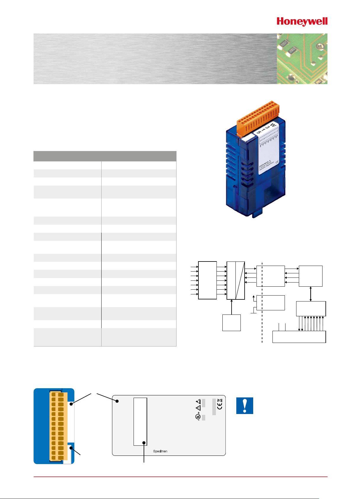
PCD3.W315
Analog input module, 7 channel, 12 bit, 0 … 20 mA,
electrically isolated from the CPU
High-speed input modules for general use with 7 channels,
each with 12 bit resolution and 0 … 20 mA. Electrically
isolated from the CPU.
Technical specications
Number of inputs (channels) 7
Signal range 0 … 20 mA
Resolution (representation) 12 bit (0 … 4095)
Resolution
(value of least signicant bit(LSB))
Galvanic separation 500 V, electrical isolation of outputs
Measuring principle non-dierential, single-ended
Input resistance 120 Ω / 0.1 %
Accuracy at 25 °C ± 0.15 %
Repeating accuracy
(under same conditions)
Temperature error (0 … +55 °C) ± 0.25 %
Conversion time A/D ≤ 2 ms
Overcurrent protection ± 35 mA (permanent)
EMV protection yes
Time constant of input lter typisch 2.4 ms
Internal current consumption
(from +5 V bus)
Internal current consumption
(from V+ bus)
External current consumption 0 mA
Terminals Pluggable 10-pole spring terminal block
5 µA
to CPU, channels themselves not
separated
± 0.05 %
Block schematic
< 60 mA
0 mA
for Ø up to 2.5 mm²,
plug type E (4 405 4998 0)
Input filter
Ref.
Voltage
2.5V
MUX
PCD3.W315
A
VCC
D
COM
Galvanic
separated
serial
interface
DC / DC
Konverter
+5V GND
Galvanic separation
PCD-Bus
μController
I/O-Bus
Indicators and connections
label
W
W
3
1
5
3
1
5
Module-
base-
adresse
51-52-03-84 Rev.2.3 – Data Sheet – PCD3.W315
0
E0
GND
1
E1
2
GND
3
E2
4
GND
5
E3
6
GND
7
E4
8
GND
9
E5
10
GND
11
E6
12
GND
13
KackbrauneKac
Specimen
Terminals
PCD3.W315
7 inputs 0…20mA
The GND connections are
connected together in the
module and are galvanically
isolated from the CPU. These GNDs must not be connected to the CPU, process
GNDs or ground !
Honeywell Process Solutions
| 1
Page 2
51-52-03-84 Rev.2.3 – Data Sheet – PCD3.W315
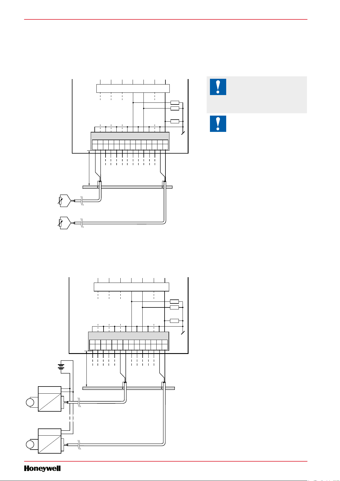
Connection concept for voltage inputs
The voltage input signals are connected directly to the 14-pole terminal block (E0 … E6 and GND). To minimize the amount of
interference coupled into the module via the transmission lines, connection should be made according to the principle explai-
ned below.
Connection for 0 … 20 mA
The GND connections are con-
Input filter
PCD3.W315 0…20 mA galvanic sep.
10111213
GND GND GND GND GND GND GND
max. 20cm
Earthing bar
0123456789
E0E1E2E3E4E5E6
nected together in the module
and are galvanically isolated
from the CPU. These GNDs
must not be connected to the
CPU, process GNDs or ground !
If shielded cables are used, the
shielding should be connected
to an earthing rail.
of
Resistance
measurement
of
Resistance
measurement
Shield
Shield
Connection for 0…20 mA with two-wire transducers
Input filter
PCD3.W315 0…20 mA galvanic sep.
GND GND GND GND GND GND GND
+
DC
24 V
-
+
Temperature
ϑ
-
4...20 mA*
2
max. 25 cm
min. 2.5 mm
10111213
Earthing bar
Shield
*) potential free
0123456789
E0E1E2E3E4E5E6
2 |
+
0...20 mA
-
Shield
* 4…20 mA by Software
Speed
υ
Honeywell Process Solutions
Page 3

51-52-03-84 Rev.2.3 – Data Sheet – PCD3.W315
Galvanic separation of inputs to CPU, channels themselves not separated.
I/O modules and I/O terminal blocks may only be plugged in and removed when the CPU and the external +24 V
are disconnected from the power supply.
Honeywell Process Solutions
| 3
Page 4

51-52-03-84 Rev.2.3 – Data Sheet – PCD3.W315
PCD3.W315 4 405 4998 0
Ordering information
Type Short description Description Weight
PCD3.W315 7 analogue inputs, 0 … 20 mA, 12 bit,
electrical isolation
Analog input module with electrical isolation,
7 channels (the channels are not isolated from each other),
resolution 12 bit, range 0 … 20 mA,
connection with pluggable spring terminals, connector type E (4 405 4998 0) supplied
Ordering information equipment
Type Short description Description Weight
4 405 4998 0 Plug-in, type E Plug-in I/O spring terminal block, 14-pole up to 1.5 mm2, labelled 0 … 13 13 g
4 |
Honeywell Process Solutions
100 g
Page 5

51-52-03-84 Rev.2.3 – Data Sheet – PCD3.W315
ATTE N TION
These devices must only be installed by a professional electrician, otherwise there is the risk of fire or the risk
of an electric shock.
WARNING
Product is not intended to be 0used in safety critical applications, using it in safety critical applications is
unsafe.
WARNING - SAFETY
The unit is not suitable for the explosion-proof areas and the areas of use excluded in EN 61010 Part 1.
WARNING - SAFETY
Check compliance with nominal voltage before commissioning the device (see type label). Check that connection cables are free from damage and that, when wiring up the device, they are not connected to voltage.
Do not use a damaged device !
NOTE
In order to avoid moisture in the device due to condensate build-up, acclimatise the device at room temperature
for about half an hour before connecting.
CLEANING
The device can be cleaned in dead state with a dry cloth or cloth soaked in soap solution. Do not use caustic or
solvent-containing substances for cleaning.
MAINTENANCE
These devices are maintenance-free.
If damaged, no repairs should be undertaken by the user.
GUAR ANTEE
Opening the module invalidates the guarantee.
Observe this instructions (data sheet) and keep them in a safe place.
Pass on the instructions (data sheet) to any future user.
WEEE Directive 2012/19/EC Waste Electrical and Electronic Equipment directive
The product should not be disposed of with other household waste. Check for the nearest authorized collection
centers or authorized recyclers. The correct disposal of end-of-life equipment will help prevent potential
negative consequences for the environment and human health.
EAC Mark of Conformity for Machinery Exports to Russia, Kazakhstan or Belarus.
Honeywell Process Solutions
| 5
Page 6

Sales and Service
For application assistance, current specications, pricing, or name of the nearest Authorized Distributor, contact one of the oces below.
ASIA PACIFIC
Honeywell Process Solutions,
(TAC) hfs-tac-support@honeywell.com
Australia
Honeywell Limited
Phone: +(61) 7-3846 1255
FAX: +(61) 7-3840 6481
Toll Free 1300-36-39-36
Toll Free Fax:
1300-36-04-70
China – PRC - Shanghai
Honeywell China Inc.
Phone: (86-21) 5257-4568
Fax: (86-21) 6237-2826
Singapore
Honeywell Pte Ltd.
Phone: +(65) 6580 3278
Fax: +(65) 6445-3033
EMEA
Honeywell Process Solutions,
Phone: +80012026455 or
+44 (0)1344 656000
Email: (Sales)
FP-Sales-Apps@Honeywell.com
or
(TAC) hfs-tac-support@honeywell.com
AMERICA’S
Honeywell Process Solutions,
Phone: (TAC) 1-800- 423-9883 or
215/641-3610
(Sales) 1-800-343-0228
Email: (Sales)
FP-Sales-Apps@Honeywell.com
or
(TAC) hfs-tac-support@honeywell.com
South Korea
Honeywell Korea Co Ltd
Phone: +(822) 799 6114
Fax: +(822) 792 9015
WARRANTY/REMEDY
WARRANTY/REMEDY
Honeywell warrants goods of its manufacture as being free of defective materials and faulty workmanship. Contact your local
Honeywell warrants goods of its manufacture as being free of defective materials and faulty workmanship. Contact your local
sales oce for warranty information. If warranted goods are returned to Honeywell during the period of coverage, Honeywell
sales oce for warranty information. If warranted goods are returned to Honeywell during the period of coverage, Honeywell
will repair or replace without charge those items it nds defective. The foregoing is Buyer's sole remedy and is in lieu of all
will repair or replace without charge those items it nds defective. The foregoing is Buyer's sole remedy and is in lieu of all
other warranties, expressed or implied, including those of merchantability and tness for a particular purpose.
other warranties, expressed or implied, including those of merchantability and tness for a particular purpose.
Specications may change without notice. The information we supply is believed to be accurate and reliable as of this printing.
Specications may change without notice. The information we supply is believed to be accurate and reliable as of this printing.
However, we assume no responsibility for its use.
However, we assume no responsibility for its use.
While we provide application assistance personally, through our literature and the Honeywell web site, it is up to the customer
While we provide application assistance personally, through our literature and the Honeywell web site, it is up to the customer
to determine the suitability of the product in the application.
to determine the suitability of the product in the application.
Specications are subject to change without notice.
For more information
Learn more about ControlEdge PCD, visit our
website www.honeywellprocess.com/ControlEdgePCD
or contact your Honeywell account manager.
Honeywell Process Solutions
2101 CityWest Blvd, Houston TX 77042
Honeywell House, Skimped Hill Lane
Bracknell, Berkshire, England RG12 1EB UK
Building #1, 555 Huanke Road,
Zhangjiang Hi-Tech Industrial Park,
Pudong New Area, Shanghai 201203
6 |
www.honeywellprocess.com
©2020 Honeywell International Inc.
Document No.: 51-52-03-84
Rev.2.3
July 2020
 Loading...