

Page 1
TRADELINE
PC8900A
Control Panel
®
INSTALLATION INSTRUCTIONS
APPLICATION
The PC8900 Control Panel provides 24 Vac energy saving
control for a heating and cooling system, while providing
reliable, precise temperature control, ventilation control,
humidity control, programmable fan control and air filter/
cleaner status information.
The PC8900 must be used with a W8900 Remote Module.
The PC8900 includes a SYSTEM light, which is lit when
the heating or cooling system is running, and a CHECK
light, which lights as a prompt to check messages on the
CHECK list.
These models will replace most heating/cooling system
thermostats. Check Table 1 to make sure the thermostat is
compatible with the intended system.
Table 1. Compatibility Chart.
System Type
Gas—Standing Pilot Yes
Gas—Electronic Ignition Yes
Gas-Fired Boilers Yes
Gas—Millivolt See Note a
Oil-Fired Boilers Yes
Oil-Fired Furnace Yes
Electric Furnace Yes
Electric Air Conditioning Yes
Baseboard Electric
(120/240 Line Volt)
Heat Pumps/Multistage Equipment Yes
a Use R8222N Relay if installing as part of millivolt
system (see W8900 Remote Module Instructions form
69-0894).
b Use R8222D Relay if installing as part of a 120/240 Vac
baseboard electric system (see W8900 Remote Module
Instructions, form 69-0894).
Compatible
with PC8900
See Note b
SPECIFICATIONS
Temperature Setting Range:
45°F to 88°F (7°C to 31°C).
Humidity Setting Range:
10% to 80%.
Operating Relative Humidity:
5% to 90%, noncondensing.
Finish:
White
Dimensions in in. (mm):
6-3/8 (163) width x 4 (102) height x 1-5/8 (41) depth.
Accessories:
205224A Wall Cover Plate to cover marks left on the
wall by the old thermostat.
C7189A Wall Mount Indoor Air Temperature Sensor.
C7089A Outdoor Sensor.
RECYCLING NOTICE
M3375
If this control is replacing a control that contains
mercury in a sealed tube, do not place your old
control in the trash.
Contact your local waste management authority for
instructions regarding recycling and the proper
disposal of any control containing mercury in a
sealed tube.
If you have any questions, call Honeywell Inc. at
1-800-468-1502, Monday through Friday, 7 AM to
5:30 PM, Central time.
U.S. Registered Trademark
Copyright © 1995 Honeywell Inc. • • All Rights Reserved
M3375
X-XX UL
69-0893-1
Page 2
PC8900A CONTROL PANEL
INSTALLATION
When Installing this Product…
1. Read these instructions carefully. Failure to follow
instructions can damage the product or cause a
hazardous condition.
2. Check the ratings on the product and the compatibility in Table 1 to make sure the product is suitable for
your application.
3. Installer must be a trained, experienced service
technician.
4. After completing installation, use these instructions
to check out product operation.
CAUTION
Disconnect power supply before wiring to prevent
electrical shock or equipment damage.
Location and Mounting
NOTE: The following location guidelines apply only if a
remote sensor is not part of the installation. If a
remote sensor is installed, the PC8900 can be
installed in any convenient location, with these
guidelines applying to the sensor location.
Locate the PC8900 where it will not be subjected to
tampering.
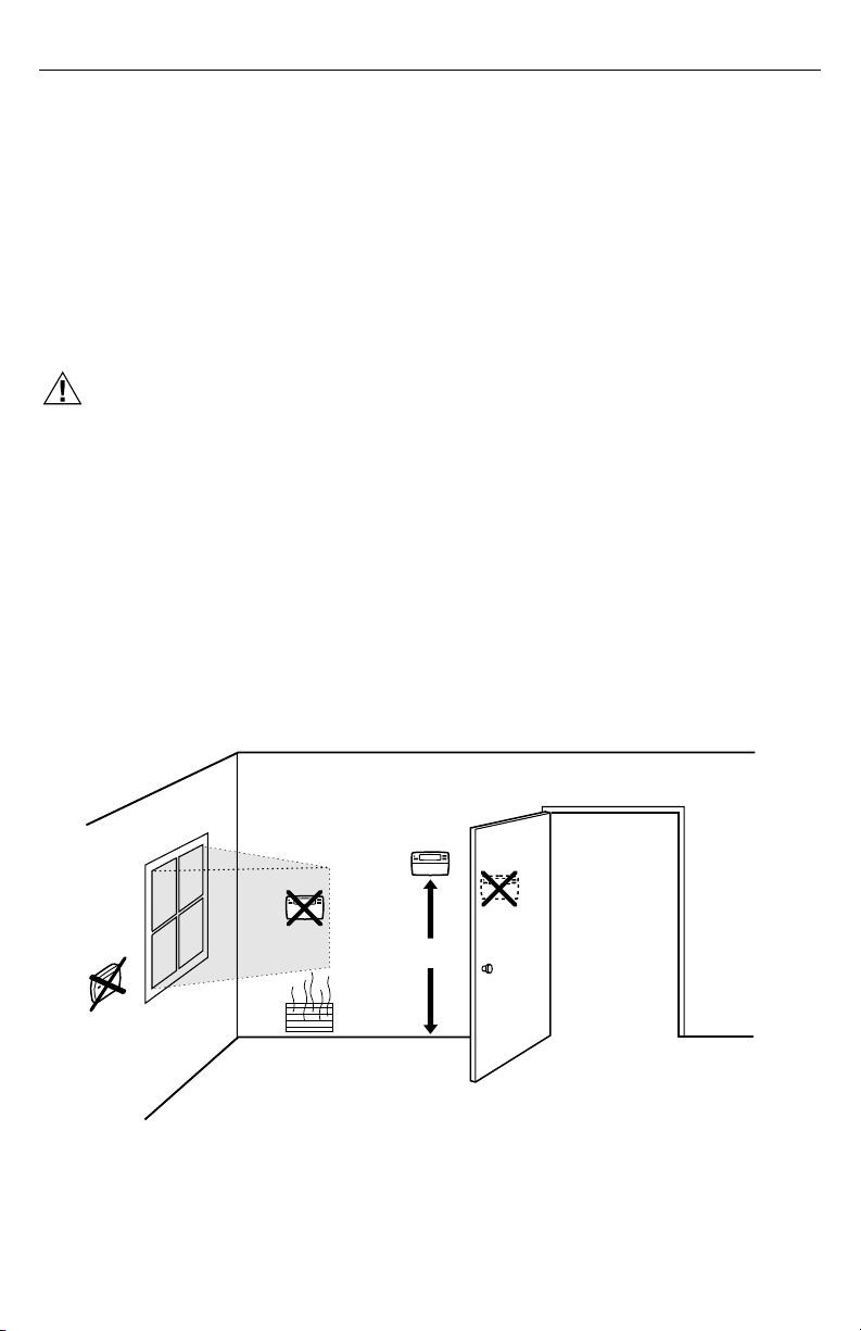
1. Choose a location on an inside wall about 5 ft (1.5m)
above the floor. A horizontally mounted standard
2 in. x 4 in. (51 mm x 102 mm) outlet box can also
be used at the selected location for the PC8900.
2. Be sure that the wire distance between the PC8900
and the W8900 does not exceed 200 feet.
3. Be sure that there is good air circulation at average
temperature at the chosen location. Avoid the
following locations because they can introduce
errors in temperature measurements.
• Hot areas caused by:
• Concealed pipes or ducts.
• Drafts from fireplaces or other heat sources.
• Convection or radiant heat from the sun or
electrical equipment.
• Cold areas caused by:
• Concealed pipes or ducts.
• Drafts from windows and doors.
• Unheated areas on the other side of the wall
location.
• Dead air areas:
• Behind doors, furniture and curtains.
• In corners and alcoves.
4. Mark the area on the wall where the PC8900 or
outlet box will be mounted.
5. Run cable to a hole at the selected wall location.
Pull approximately 3 inches of wire through the
opening. Color-coded 18-gauge thermostat wire is
recommended.
6. Position wiring plate on wall.
7. Level the wiring plate, for appearance only, using
the posts on top of the wiring plate. Device will
function properly even when not level.
8. Mark three mounting holes using a pencil.
9. Remove wiring plate from wall and drill 3/16 inch
holes in wall, if drywall, as marked. For firmer
material such as plaster or wood, drill 7/32 inch
holes. Gently tap anchors provided into drilled holes
until flush with the wall. See Fig. 2.
10. Position wiring plate over holes in wall or outlet box,
pulling wires through wiring opening. Loosely insert
two mounting screws into holes.
11. Tighten mounting screws.
69-0893—1
YES
NO
NO
NO
Fig. 1. Typical Location of PC8900.
5 FEET
(1.5 METERS)
2
M6394
Page 3

NOTE: If the old thermostat has left marks on the wall
M7518
FOR WRAPAROUND
INSERTION STRIP
7/16 in. (11mm).
FOR STRAIGHT
INSERTION STRIP
5/16 in. (8mm).
that are not covered by the PC8900, order part
no. 205224A Wall Cover Plate to mount between
the wall and the PC8900.
WALL
ANCHORS
(3)
WALL
1
MOUNTING
SCREWS (3)
MOUNTING
HOLES (4)
M4466
WIRES
THROUGH WALL
USE THREE MOUNTING HOLES THAT BEST
1
FIT APPLICATION
Fig. 2. Mounting PC8900 Wiring Plate.
PC8900A CONTROL PANEL
CAUTION
Disconnect power supply before connecting wiring
to prevent electrical shock or equipment damage.
All wiring must comply with applicable electrical codes,
ordinances, and regulations.
1. Loosen the terminal screws and insert one wire
beneath each numbered terminal (1,2,3,4). Note the
color of wire that is attached to each terminal
number to later match the colors with the terminals
on the W8900 Remote Module. See Fig. 3 and 4 for
technique and wiring diagram. Four wires are
required at the thermostat to assure operation.
2. Securely tighten screw terminals.
3. Push excess wire back into the hole. Plug the hole
with nonhardening caulk, putty or insulation to
prevent drafts from affecting PC8900 operation.
IMPORTANT
In replacement applications, more than four wires
may be available. In these applications, tape off
the unused wires at the PC8900 location and
W8900 location.
1
WIRING
CAUTION
Keep wiring at least one foot away from large
inductive loads such as motors, line starters,
lightning ballasts and large power distribution
panels. Failure to follow these wiring practices can
introduce electrical interference (noise), which can
cause erratic system operation. Use shielded cable
to reduce interference when rerouting is not
possible. Ground the shielded cable to the GND
terminal on the W8900.
IMPORTANT
Erratic temperature readings can occur as a
result of any of the wiring practices described
below. These practices must be avoided to
assure proper operation. Use shielded cable to
reduce interference when rerouting of wiring is
not possible.
a. Do not route thermostat wiring with building
power wiring, next to control contactors or
near light dimming circuits, electric motors or
welding equipment.
b. Avoid poor wiring connections.
c. Avoid intermittent or missing building earth
ground.
Fig. 3. Proper Wiring Technique.
3
69-0893—1
Page 4

PC8900A CONTROL PANEL
3
GND
1
2
3
4
1
2
1
1234
W8900
Mounting the PC8900 on the Wiring Plate
To mount the PC8900 on the wiring plate, engage the tabs
on the wiring plate with the back of the PC8900 and then
press the PC8900 to latch.
OPERATION
The PC8900 is not a typical thermostat. It senses temperature and humidity conditions in the living space and
transfers the information to the W8900 Remote Module.
The W8900 activates the proper equipment based on
room conditions and programmed settings.
CHECKOUT
WARNING
Do
not
jumper any PC8900 wires in an attempt to
activate equipment.
See checkout procedures included with W8900 Remote
Module.
To test for 24V at the PC8900, measure between terminals 1 and 4.
CALIBRATION
The PC8900 is calibrated at the factory and cannot be
recalibrated in the field.
2
PROGRAMMING
See Owner’s Guide, form 69-0891, for programming
instructions.
1
NOTE WHICH COLOR WIRE IS ATTACHED TO EACH TERMINAL.
2
FOUR WIRES ARE REQUIRED FOR PROPER OPERATION.
IF FEWER THAN FOUR ARE AVAILABLE, ADDITIONAL WIRES
MUST BE RUN TO PC8900 LOCATION. IF MORE THAN FOUR
ARE AVAILABLE, TAPE OFF UNUSED WIRES.
3
IF SHIELDED CABLE IS REQUIRED, GROUND TO GND
TERMINAL ON W8900.
Fig. 4. Wiring Diagram for PC8900 to
the W8900 Remote Module.
Home and Building Control
Honeywell Inc.
1985 Douglas Drive North
Golden Valley, MN 55422
69-0893—1 J.H. Rev. 5-95
69-0893—1
POWER OUTAGES
The PC8900 requires no backup batteries. In event of
power outage, the time of day and day are retained for
approximately six hours. Program times, temperatures,
M7519
and settings will be held indefinitely.
NOTE: When power is restored, the time and day
W8900 REMOTE MODULE
INSTALLATION
To install the W8900 Remote Module, refer to form
69-0894 for instructions packed with the remote module.
Home and Building Control
Honeywell Limited-Honeywell Limitée
35 Dynamic Drive
Scarborough, Ontario
M1V 4Z9
4
information must be re-entered.
 Loading...