

Honeywell NEXPTZ-PD, NEXPTZ-WL, NEXPTZ-CN, NEXPTZ-PL Installation And Operation Manual
- 1 -
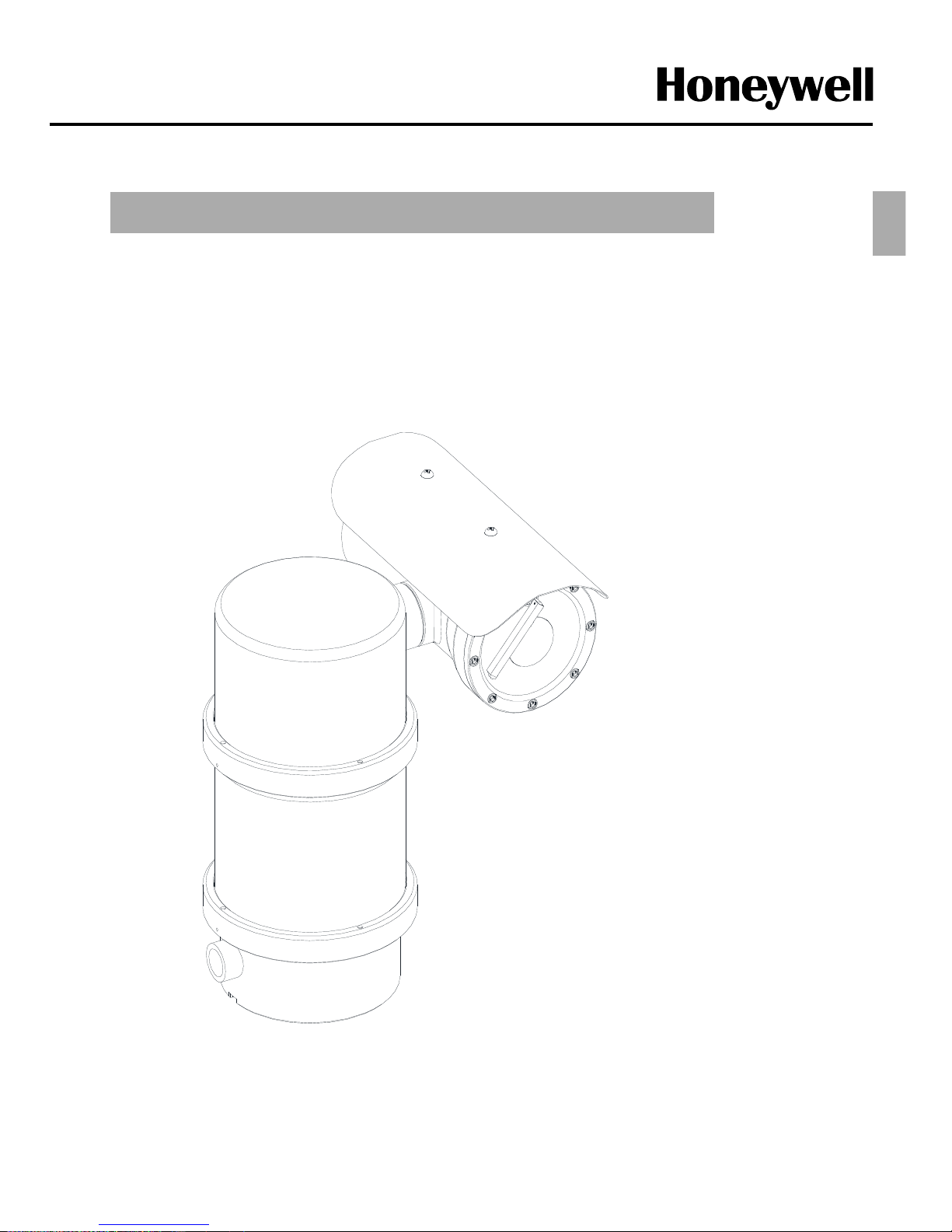
NEXPTZ Camera
Explosion proof Security Camera
(High Speed Standard Type)
INSTALLATION & OPERATION GUIDE BOOK
ENG

- 2 -
1. Install and use this system after reading these instruction thoroughly.
2. Keep these instructions.
3. Install in accordance with the manufacture’s instruction.
4. Take care of all Cautions and Warnings.
5. Use stainless steel hardware to fasten the mount to outdoor surfaces.
6. Only use replacement parts recommended by the manufacturer.
RISK O F ELEC TRIC SHO CK
DO N OT OPEN
CAUTION
CAUTION : TO REDUCE THE RISK OF ELECTRIC SHOCK.
DO NOT REMOVE COVER(OR BACK).
NO USER SERVICEABLE PARTS INSIDE
REFER SERVICING TO QUALIFIED SERVICE PRERSONNEL
Explanation of Graphical Symbols.
This symbol is intended to alert the user to the presence of uninsulated
“dangerous voltage” within the product’s enclosure that may be of sufficient
magnitude to constitute a risk of electric shock to persons.
This symbol is intended to alert the user to the presence of important
operating and maintenance(Servicing) Instructions in the literature
accompanying the appliance.
TO REDUCE THE RISK OF IGNITION DO NOT OPEN WHEN AN EXPLOSIVE
GAS ATMOSPHERE MAY BE PRESENT
WARNING: To reduce the risk of ignition of hazardous atmospheres, conduit runs
must have a sealing fitting or cable gland connected within PT 3/4 inches of the
enclosure.
WARNING: To reduce the risk of ignition of Hazardous Atmospheres,
disconnect the equipment from the supply circuit before opening.
Important Safety Instructions
ENG
- 3 -
WARNING: Gross weight of this system is about 30kg. Use caution when lifting
and installing. It is recommended you to wear proper non-slip gloves be worn during
installation.
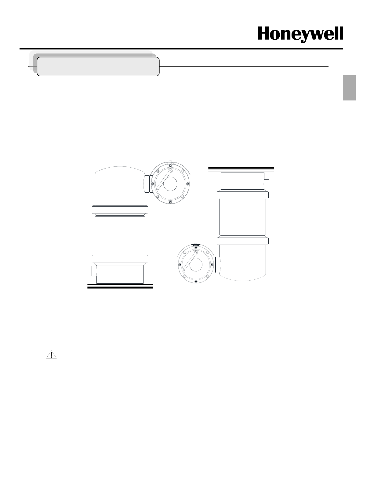
Figure1.
Method of Installation
Standard Position
Inverted Position
This system can be installed in a standard or inverted position or camera Housing only with
optional bracket as below Figure1.
When installed for inverted operation, the origin of camera shall be reconfigured through the
Camera function. There is no need to be adjusted physically but sunshield bracket may not
be functional at this case.
Methods of Installation
ENG
- 4 -
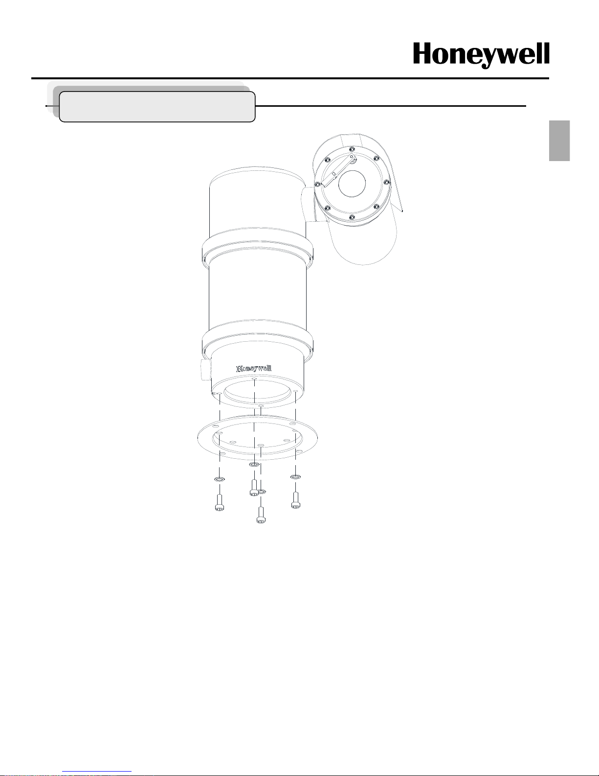
Install the product to Pedestal Mount bracket
To install this product, please refer to Figure2 and do the following steps.
1. Make sure the threads of the product and the threads of the supplied M8X15mm stainless steel bolts
(Supplied) are free of dirt and debris.
2. Apply an amount of thread locking compound(not supplied) to the thread of the product and the thread of
the bolts.
3. Secure the product to the mounting surface with the adjusted wrench and four M8x15mm stainless steel
bolts and lock washers. Tighten the bolts to 250~350 kgf.cm (24Nm~34Nm)
Figure2.
Note : Figure2 shows the product being installed on a Pedestal mount which is an optional
product (not supplied) and if there is no need the pedestal mount, just follow a above step to install
the product without pedestal mount bracket.
Methods of Installation
ENG
- 5 -
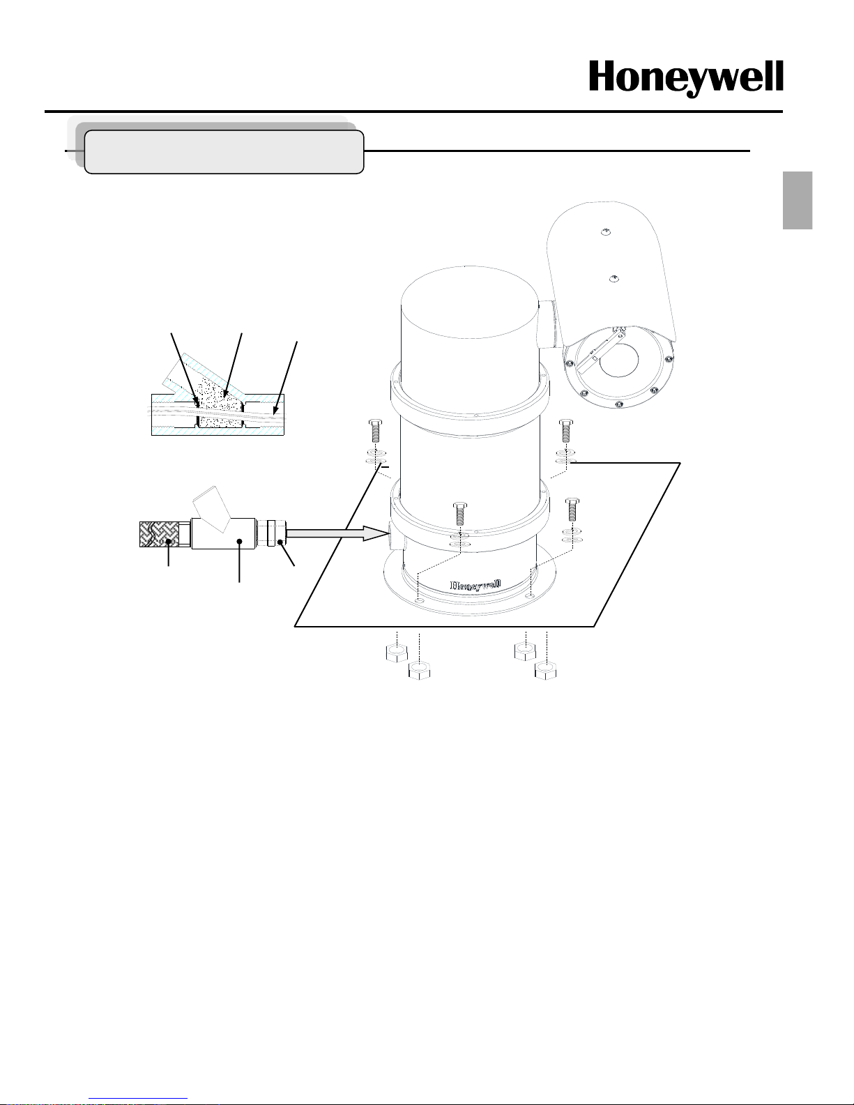
Figure3.
Note : Figure3 shows the product being installed on a surface with pedestal mount.
Install Product to the surface with Pedestal mount bracket
PT 3/4 “-14
Seal Fitting
(Not Supplied)
Explosion proof
Flexible conduit
(Not Supplied)
PT 3/4”-14 Nipple
(Supplied)
Fiber Filler
Sealing
compound
Cables
Sealing Method
To install this product, please refer to Figure3 and do the following steps.
1. Make sure the threads of the supplied four M10X30mm stainless steel bolts (Not Supplied) and flat/spring
washers are free of dirt and debris.
2. Apply an amount of thread locking compound(not supplied) to the thread of the product and the thread of
the bolts.
3 There are more options such as wall, corner and pole mount bracket to install. (refer to the mount bracket
part page)
4. Make sure the seal fitting(not supplied) and the threaded hole of this system are free of the dirt and
particles.
5. Assemble Nipple(supplied), the threaded hole of this system, seal fitting and flexible conduit(not supplied)
to be fasten firmly and then the cables must be passed through the seal fitting, nipple and flexible conduit.
Plus, the sealing fitting, flexible conduit should be acquired IECEx Certification.
Methods of Installation
ENG
- 6 -
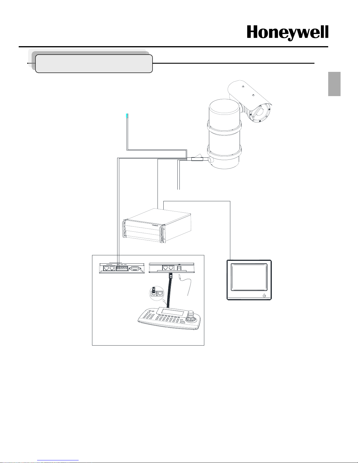
Figure4.
Base Schematic of Installation
POWER
AC110 or 220V
BNC
MAIN MONITOR
DATA1 DATA2
+ - -+ + -
REAR
FRONT
KEYBOARD CONTROLLER
HTX-5000
REAR
DATA 2 DATA 1
DC 12V
RS 485
1 DOME 2
IN OUT
DVR
RS 232C
ALARM/DVR
DC 12V
SLAVE
RS 485
+
-
Alram out
COM
N/O
RS 485
DVR
1. Figure4 is recommended for the base Schematic of Installation.
2. If you wish to consist of another method or other components, you must proceed to do after
conferring with a manufacture.
3. Depend on a DVR, you can control the product with an Utility in the DVR without HTX-5000.
Base Schematic
ENG
- 7 -
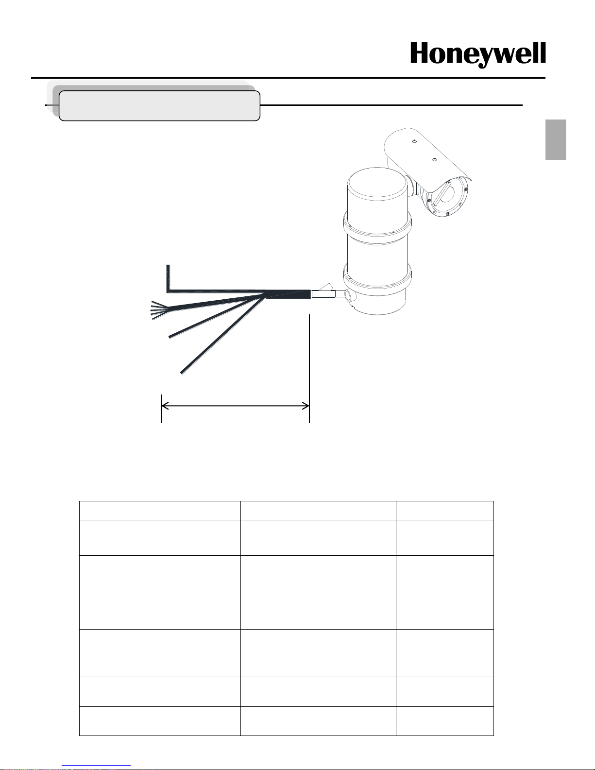
Configuration of Wire Harness
POWER
(AC 220V or 110V)
BNC
Alram
In/Out Put
RS-485
Data+, -
Figure8.
Cable configuration
2m ± 0.3m
Cable Configuration
Wire Color Function Description
Brown
Sky Blue
Green
Power Input
(AC 100V ~ 240V)
L1
N
GND
Red
Orange
Yellow
Green
Black
Alarm Input
Alarm 1
Alarm 2
Alarm 3
Alarm 4
GND
Black
Red
Yellow
White
Alarm Output A
Alarm Output B
NO A
COM A
NO B
COM B
Black
(Coaxial cable)
Video BNC Cable
Blue stripe
White stripe
Control Data
RS485 Data +
RS485 Data -
ENG

- 8 -
Key Feature and Introduction
The NEXPTZ Series camera which is Explosive proof camera features a high resolution Super
HAD CCD imager for enhanced lowlight sensitivity. The NEXPTZ Series follow the stringent
explosion-proof requirements with creative mechanical strength and design. Moreover, the
NEXPTZ explosion-proof system is designed to meet the rigorous requirements of explosionproof electrical equipment installed in hazardous locations. The system has built-in True Day
&Night zoom camera with programmable Camera setting easy to setup and program functions.
System information aides trouble shooting by displaying the hardware and software version of
the dome driver, baud rate, and protocol.
The Highest level Ex Class : Ex d IIC T6 (IECEx, ATEX, CE, FCC, KC)
Corrosion resistant SUS 316 Construction
IP67 Protection
Adapt 650TVL, Optical x36 AF Zoom module
360º Continuous Panning with max 60º/sec High Speed
Thanks to Flip function and 360º continuous rotate at Pan/ Tilt angle
Various Preset function
- Home Function
- 128 Preset potions w/ focus, iris, BLC setting
- 8 Scan ,4 Tours, Pattern
Built-in Wiper function
4 Alarm in & 2 Relay out
Integrated with Washer jet : EXWJ400
Approx 30Kg of light weight
ENG
- 9 -
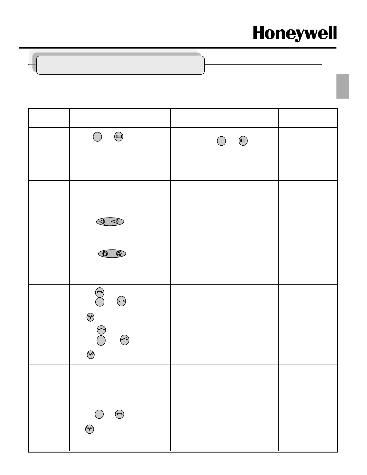
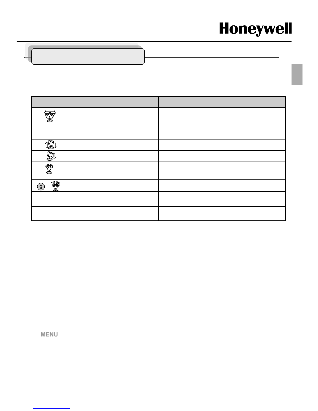
* This function is specialized to HTX-5000 keyboard.
Remarks Results Process Function
-ZOOM IN
-ZOOM OUT
-Focus is changed to Near or Far
-Return to Auto Focus mode by
moving the joystick.
-Iris is opened or closed
Moving the joystick reactivates Auto Iris
mode
ZOOM
/FOCUS/
Iris
For matching ID 01
If ID set 02, press and (Cam)
button
You can see the moving as following the
direction.
①
Press and (CAM) button
in sequence.
②
Move Joystick to the right,
left, up and down.
PAN/TILT
1
①
Twist Joystick to the right.
②
Twist Joystick to the left.
③
Press button.
④
Press button.
2
If it’ not raining,
forbid to keep the
moving status over
1 hour continually.
-Wiper moves as keeping a steady angle.
-Wiper stops.
Wiper
Control
①
Press (On) button or
Press and (On) button
in sequence.
(86+ Preset) at Pelco Protocol
②
Press (Off) button or
Press and (Off) button
in sequence.
(79+ Preset) at Pelco Protocol
2
2
Water jet
(Optional)
①
Set washing position
-.Move the window face to nozzle by
using pan/tile and save the position
on preset 59.
②
Press and (On) button.
(88+ Preset) at Pelco Protocol
- Set the specific position to wash front
window toward the nozzle on preset 59.
-Run washing and wiping.
4
Check water level in
the tank periodically.
Simple Function Control Guide
ENG
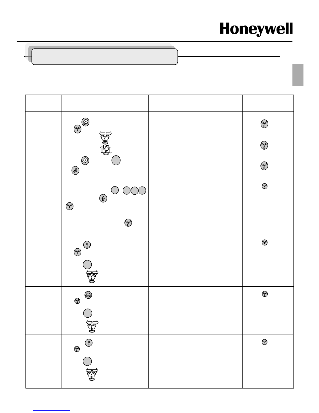
- 10 -
①
Press (Pattern) button to set.
(80+ Preset) at Pelco Protocol
② Press (Esc) button or move
Joystick to the right or left.
①
Set Preset (direct)
-.Select one button of ~ ,
(128) and Press (Shift) and
(Preset) in sequence.
②
Running Preset
-.Press Number button and
in sequence.
-PTZ moves to the position which you
have saved the preset.
~
Simple Function Control Guide
Remarks Results Process Function
-Menu screen is displayed.
-Go into the sub-menu items.
Change value.
Navigate through the menu items
-Navigate through the menu items.
-Escape from the menu.
Menu
① Press (Menu) button.
(95+ Preset) at Pelco Protocol
② Move Joystick to the right
or left.
③ Move Joystick Up or Down.
④ Press (Menu) or (Esc)
or (Enter) button twice.
ESC
(Enter)
= (94+ Preset)
at Pelco protocol
(Menu)
= (95+ Preset)
at Pelco protocol
(ESC)
= (96+ Preset)
at Pelco protocol
Scan
①
Press (Scan) button to set.
(60+ Preset) at Pelco Protocol
② Press (Esc) button or move
Joystick to the right or left.
Preset
-PTZ continually moves between the start
and end point which user set among the
preset.
-Escape from the moving Auto Pan.
ESC
1
1
2
8
Tour
①
Press (Tour) button to set.
(70+ Preset) at Pelco Protocol
② Press (Esc) button or move
Joystick to the right or left.
ESC
1~59+ Preset to
operate Preset 1~59
at Pelco protocol.
-PTZ continually moves to user set
position of the presets.
-Escape from the moving Tour.
61~68+ Preset to
operate Scan1~8 at
Pelco protocol.
71~74+ Preset to
operate Tour1~4 at
Pelco protocol.
Pattern
ESC
-PTZ continually moves to user set
position of the presets.
-Escape from the moving Tour.
81~84+ Preset to
operate Pattern1~4 at
Pelco protocol.
ENG
- 11 -
Program and Operation
NEXPTZ cameras must be set up communication before starting the installation. This involves
properly setting configuration of Camera ID, BAUDRATE and PROTOCOL.
To do set communication initially,
You should use the Remote controller which is included to the product additionally.
Remote controller can set up communication regardless of Camera ID, BAUDRATE and
PROTOCOL
When you use the remote controller, the remote controller is better to be towards the window of
Camera housing .
MENU Communication Select CAMERA ID / BAUDRATE / PROTOCOL
Delete value or name of the field.
Home or Off button
Escape from the menu without change.
ESC
PTZ control mode.
SHFT + Joystick
Change value.(Increase / Decrease)
Enter editing title mode.
Zoom handle twist
Finish editing title.
Joystick down
Navigate through the menu items.
Joystick up or down
Go into the sub-menu items.
Execute the command(exit)
Change value.
Navigate through the menu items.
Joystick left or right
Function Button or Joystick movement in menu
Principle of joystick usage in the programming (editing) mode
* This function is specialized to HTX-5000 keyboard.
Camera Setting (Camera ID, BAUDRATE, PROTOCOL)
ENG

- 12 -
Program and Operation
1. FUNCTIONS
1.1 HOME FUNCTION (MENU Functions Home)
1.2 PRESET (MENU Functions Preset or Shortcut: PRST)
1.3 SCAN (MENU Functions Scan or Shortcut: SCAN)
1.4 TOUR (MENU Functions Tour or Shortcut: TOUR)
1.5 PATTERN (MENU Function Pattern or Shortcut: PTRN)
1.6 EXIT
2. ALARM
2.1 ALARM SETUP
2.2 SAVE AND EXIT
3. SCREEN
3.1 PRIVACY ZONE (MENU Screen Privacy Zone)
3.2 NORTH DIRECTION (MENU Screen North Direction)
3.3 ZONE TITLE (MENU Screen Zone Title)
3.4 CAMERA TITLE (MENU Screen Camera Title)
3.5 OSD DISPLAY (MENU Screen OSD Display)
3.6 EXIT
4. CAMERA
4.1 FOCUS CONTROL (MENU Camera Focus Control)
4.2 WB CONTROL (white balance) (MENU Camera WB Control)
4.3 AE CONTROL (auto exposure) (MENU Camera AE Control)
4.4 BLC/WDR SETUP (MENU Cemera BLC/WDR Setup)
4.5 SHARPNESS (MENU Camera Sharpness)
4.6 DIGITAL ZOOM (MENU Camera Digital zoom)
4.7 NIGHT SHOT (MENU Camera Night Shot)
4.8 CAMERA DEFAULT (MENU Camera Camera Default)
4.9 SAVE AND EXIT
5. SETUP
5.1 INSTALLATION (MENU Setup Installation)
5.2 SPEED (MENU Setup Speed)
5.3 PANNING RANGE (MENU Setup Panning Range)
5.4 CALIBRATION (MENU Setup Calibration)
5.5 FACTORY DEFAULT (MENU Setup Factory default)
5.6 ERASE DATA (MENU Setup Erase data)
5.7 SYSTEM INFORMATION (MENU Setup System Information)
5.8 SAVE AND EXIT
6. PASS WORD
6.1 ENABLE PASSWORD (MENU Password Enable Password)
6.2 EDIT PASSWAORD (MENU Password Edit Password)
6.3 SAVE AND EXIT
7. COMMUNICATION
7.1 EXPTZ ID (MENU Communication EXPTZ ID)
7.2 BAUDRATE (MENU Communication Baudrate)
7.3 PROTOCOL (MENU Communication Protocol)
7.4 SAVE AND EXIT
8. RUN FUNCTION
8.1 FUNCTION
8.2 NUMBER
8.3 RUN
8.4 EXIT
MENU TREE
ENG
- 13 -
Main Menu
Function
Alarm
Screen
Camera
Setup
Password
Communication
Run Function
Exit
Program and Operation
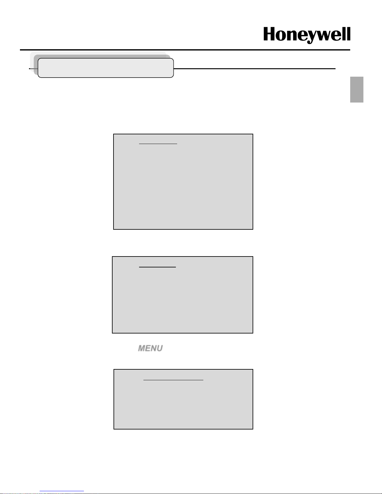
1. FUNCTION
Pressing the MENU button on the keyboard controller, the following On-screen MAIN MENU will
be shown on your monitor screen
Locate the cursor on the FUNCTION item and then push the joystick to the right to enter
FUNCTION menu.
1.1 HOME FUNCTION (MENU =>FUNCTION => HOME FUNCTION)
After HOME FUNCTION item has been selected, follow the directions below to set HOME
function.
Home Function
Function : Tour
Number : --Time : 010 SEC
Operation : DISABLE
Save And Exit
Function : Tour/ Preset/ Scan
Number : - - -
Time : 10~240 Seconds
Operation : ENABLE/ DISABLE
Function
Home Function
Preset
Scan
Tour
Pattern
EXIT
ENG
 Loading...