

Page 1
vom Kaltwassernetz
NA 228 S-B
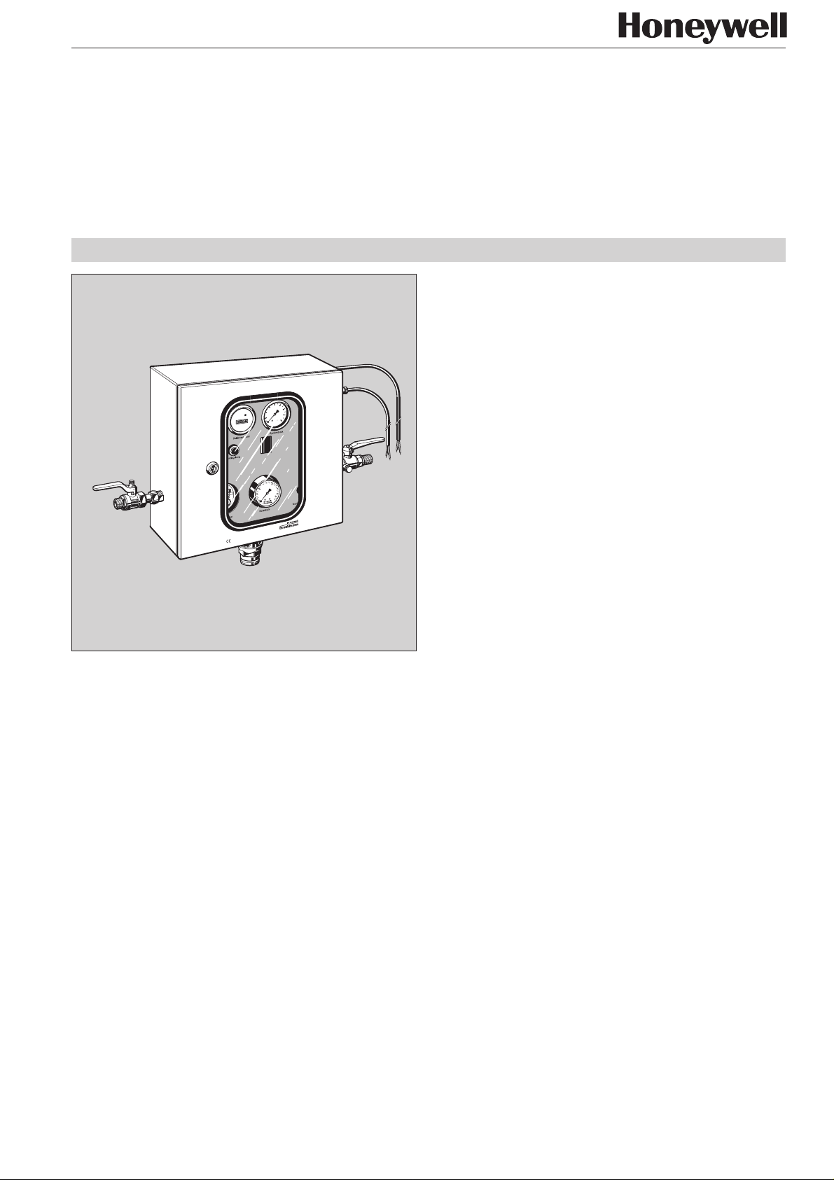
Automatic refilling unit
for compressor level control
Product specification sheet
Application
The NA 228 S-B automatic refilling unit with DVGW-tested backflow preventer permits the fixed connection of closed heating or
cooling systems to the drinking water supply network.
It integrates a backflow preventer, a check valve and a water
meter in one single unit. The automatic refilling unit maintains
pressure between prescribed upper and lower limits in closed
4
6
GRÄSSLIN
2
bar
8
0
h
220V~50Hz
Z 52
UW
10
5
SPX
1996
15
bar
16
0
heating and cooling systems. It prevents back flow, back
syphonage or back pressure of the heating or cooling water
into the potable water network. Limitation of the refilling time is
provided as well as the facility for fast and automatic refilling of
the system. In addition, build up of steam in the system caused
by pressure loss is prevented.
50/60 Hz
30 Watt
Nachfüllautomat Typ: NA 228
TÜV / DVGW
230V ~
Construction
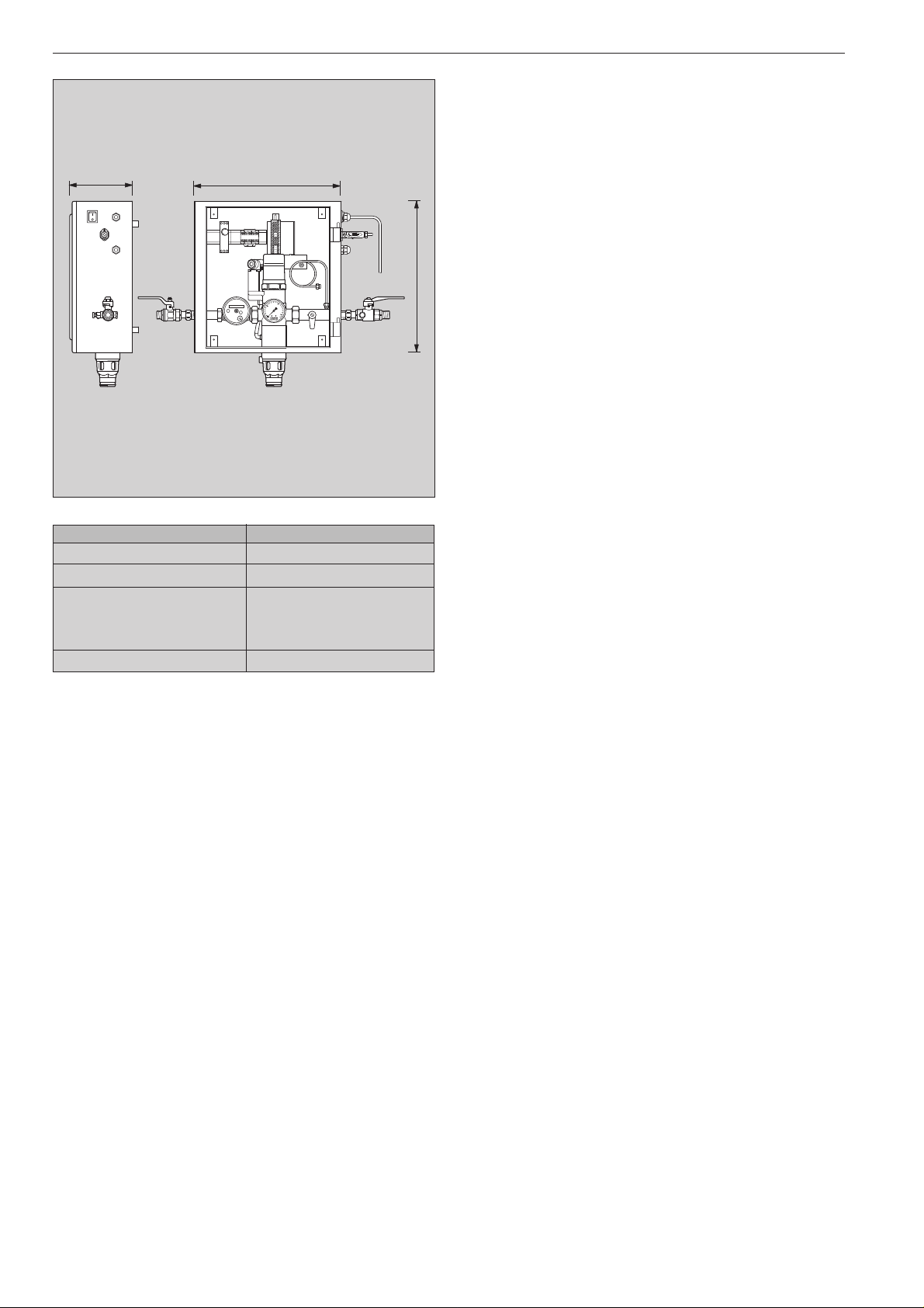
The automatic refilling unit comprises:
● Powder coated pressed steel housing
● Drinking water and system connection with shutoff
ball valve
● Electronic time relay
● Fault indicator lamp and cut-out button
● Pressure gauges for inlet and system pressure
● Discharge tundish
● Electrical plug for compressor side connection
● ON/OFF switch
● 1 metre connection cable without plug
● Water meter
● Bush for cable connection to a building management
system
● Operating-time meter
* For temperatures above 100 ºC, the pressure at the highest point in the cold system
must be at least 1.0 bar above the operating pressure (static height plus 1.0 bar).
**A pressure reducing valve must be fitted before the refilling unit for pr essur es
above 6.0 bar
Subject to change 03/99
Special Features
● Components DVGW-approved
● Electrical changeover valve for control of the backflow
preventer
● Supplementary hot-water-resistant check valve for
increased protection of the drinking water network
● Setting facility for fast filling or refilling of the system
● Time relay, for limitation of the refilling period
● Standardised discharge connection
● Remote volt-free connection
● Bush for cable connection to a building management system
● Circuit protection for volt-free connection
● Operating-time meter, measures the refilling time
● Water meter, measures the refills
Range of Application
The following operating data applies for the downstream system:
System pressure: Maximum 6.0 bar
Temperature: Maximum 120 ºC
Technical Data
Refilling Flow rate 110 litres/h at ∆p = 2.0 bar
Fast filling Flow rate finely adjustable
between 110 litres/h and
1100 litres/h at ∆p = 2.0 bar
Filling duration Adjustable between 5 and 100 minutes
Water inlet pressure Minimum 3.0 bar, maximum 6.0 bar**
Remote connection 220 V, 50/60 Hz to activate compressor
level indicator switch „lack of water“
Volt-free contact
Supply voltage 230V, 50/60 Hz
Power consumption 30W
Connection size: R
1
/2" and Ø15
225
Page 2
Automatic Refilling unit NA 228-SB
T
NETZ
EIN/AUS
zur Heizungsanlage
Fremdanschluß
- potentialfrei -
B
00 00 000 0
5
0
Method of Operation
If the system pressure falls below the lower set value, for
example through leakage losses, then the changeover valve is
opened by the compressor level control „lack of water“ and
thereby permits water supply to the backflow preventer. The
inlet pressure moves the backflow preventer to the flow
position and the system is refilled until the pressure rises to the
upper set limit. The time period of the refill is monitored by the
time relay and the operating time counter. Once the upper limit
value has been reached, the compressor level control „vessel
H
10
bar
15
16
filled“ closes the changeover valve and the backflow preventer
goes to the shutoff position. The time relay then returns to the
initial position.
If the inlet pressure falls to the set pressure of the backflow
preventer during the automatic refilling operation, then the
backflow preventer (2 bar) automatically goes to the shutoff
position. The shutoff position of the backflow preventer is
indicated in the viewing window (green visible = shutoff
position)
Option
NA 228 S-B
Connection size R
1
/2"
Soldered connection size (mm) Ø15
Weight (approx. kg) 16
Dimensions (mm)
H 380
B 370
T 160
Test Certificate Number 101/87/147
226
Braukmann Water Control . Honeywell AG
Subject to change 03/99
Page 3
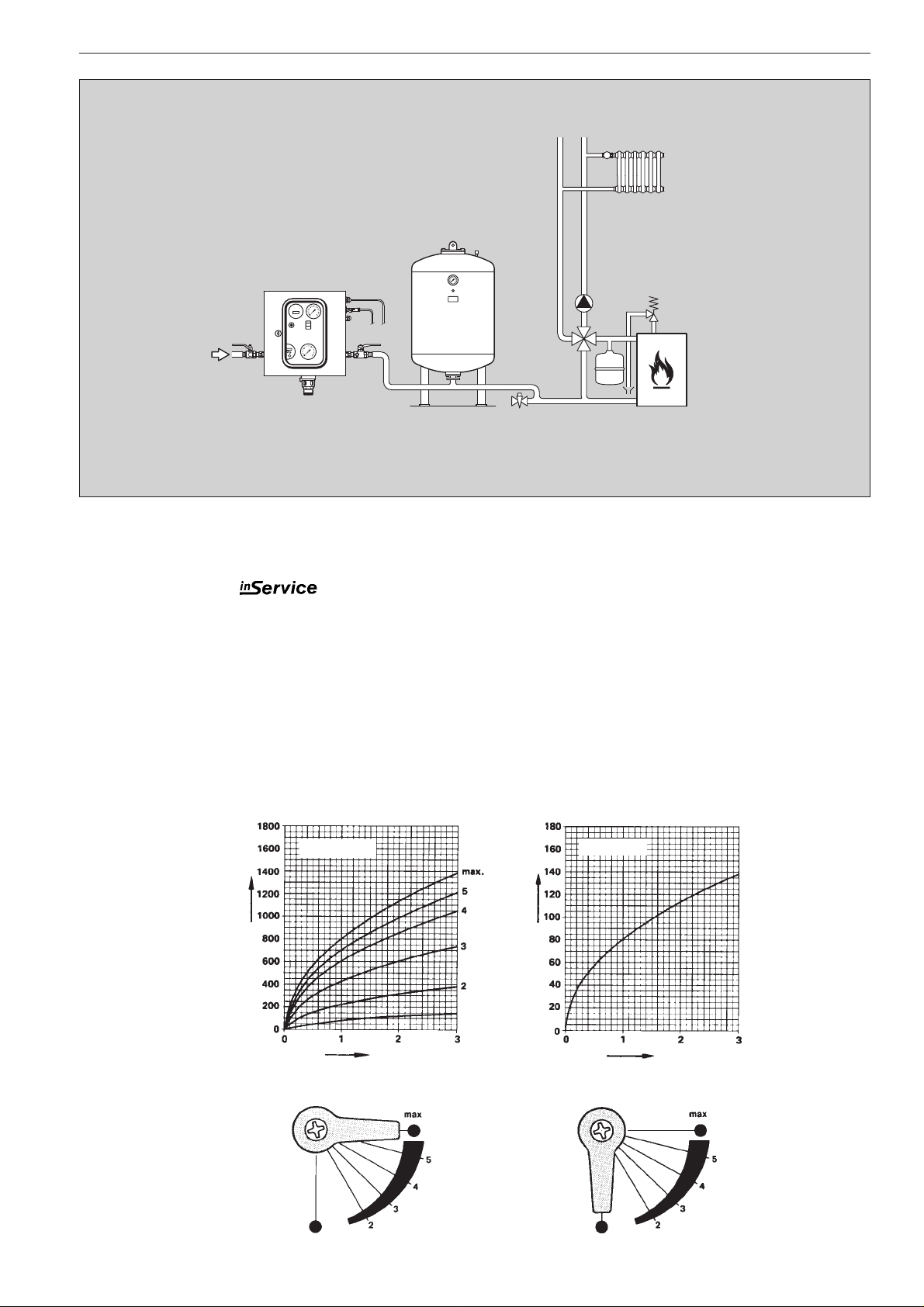
Installation Example
Automatic Refilling unit NA 228-SB
Installation Guidelines
● Fix appliance to wall
● Fit shutoff valves
❍ With shutoff valves
is possible maintenance and service without removal from the
system
● Ensure good access
❍ Simplifies maintenance and inspection
● For supply pressures over 6.0 bar fit a pressure reducing
valve on the inlet
● Check hydraulic connections for leaks
● Check time setting on time relay
Flow diagrams
Filling curves
Fast filling
Typical Applications
NA 228 S-B automatic refilling units permit a fixed connection
of closed heating and cooling systems to the drinking water
network.
Automatic refilling units are used:
● If the system pressure has to be maintained constant
● For fast and automatic refilling of the installation
● If build up of steam in the system caused by loss of
pressure must be prevented
● To limit the refilling time
Refilling
Setting
Flow rate V (litres/h)
∆p (bar)
Fast filling
Refilling Refilling
Subject to change 03/99 Braukmann Water Control . Honeywell AG
Refilling
Flow rate V (litres/h)
∆p (bar)
227
Page 4
Automatic Refilling unit NA 228-SB
②
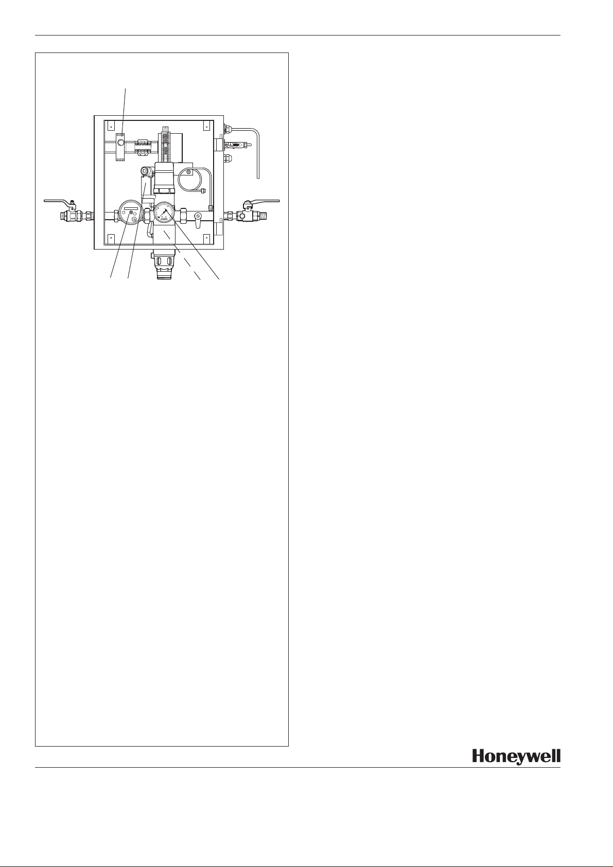
Spare Parts - NA 228 S-B automatic refilling unit
(1997 and onwards)
Description Part No.
① Water meter 0903110
② T ime relay 0903112
③ Operating time meter* 0903113
00 00 000 0
10
5
bar
15
0
16
④ Changeover valve 0901407
⑤ Discharge tundish* 0901340
⑥ Pressure gauge M 07 K - A16
①
④
⑥
⑤
⑦ Pressure gauge M 228 S - A8
for system pressure*
* Not visible in illustration
Subject to change 03/99
Braukmann Water Control . Honeywell AG
P.O. Box 1347
D - 74819 Mosbach-Germany
Phone:
(49) 62 61/ 06261/810 · Fax: 06261/8 13 09 http://europe.hbc.honeywell.com
228
 Loading...