


N2024 / N20230
N3424 / N34230
DAMPER ACTUATORS 20/34 Nm (177/300 lb-in) FOR FLOATING / 2-POSITION CONTROL
GENERAL
These direct-coupled damper actuators provide two-position and floating control for:
•air dampers,
•VAV units,
•air handlers,
•ventilation flaps,
•louvers, and
•reliable control for air damper applications with up to 4.6 m2 / 50 sq.ft. (20 Nm / 177 lb-in) or 7.8 m2 / 85 sq. ft. (34 Nm / 300 lb-in) (seal-less dampers; air frictiondependent).
FEATURES
•New self-centering shaft adapter
•Access cover to facilitate connectivity
•Declutch for manual adjustment
•Mechanical end limits
•Field-installable auxiliary switches
•Rotation direction selectable by switch
•Mountable in any orientation (no IP54 if upside down)
•Mechanical position indicator
|
|
|
PRODUCT DATA |
SPECIFICATIONS |
|
|
|
Supply voltage |
|
|
|
N2024 / N3424 |
24 |
Vac ±15%, 50/60 Hz |
|
N20230/N34230 |
230 |
Vac ±15%, 50/60 Hz |
|
Nominal voltage |
|
|
|
N2024 / N3424 |
24 |
Vac, 50/60 Hz |
|
N20230/N34230 |
230 |
Vac, 50/60 Hz |
|
All values stated hereinafter apply to operation under nominal voltage conditions.
Power consumption |
|
N2024 |
6 VA / 6 W |
N20230 |
8 VA / 8 W |
N3424 |
9 VA / 9 W |
N34230 |
13 VA / 10 W |
Ambient limits |
|
Ambient operating limits |
-20...+60 °C (-5...+140 °F) |
Ambient storage limits |
-40...+80 °C (-40...+175 °F) |
Relative humidity |
5...95%, non-condensing |
Safety |
|
Protection standard |
IP54 as per EN 60529 |
Protection class |
II as per EN 60730-1 |
Overvoltage category |
III |
Lifetime |
|
Full strokes |
60000 |
Repositions |
1.5 million |
Mounting |
|
Round damper shaft |
10...27 mm (3/8...1-1/16") |
Square damper shaft |
10...18 mm (3/8...11/16"); |
|
45° steps |
Shaft length |
min. 22 mm (7/8") |
End switches (when included) |
|
Rating |
5 A (resistive) / 3 A (inductive) |
Triggering points |
5° / 85° |
Torque rating |
|
N2024 / N20230 |
20 Nm (177 lb-in) |
N3424 / N34230 |
34 Nm (300 lb-in) |
Runtime |
110 sec (50 Hz) / 95 sec (60 Hz) |
Rotation stroke |
95° ± 3° |
Dimensions |
see "Dimensions" on page 8 |
Weight (without cables) |
1.45 kg (3 lbs. 3 oz.) |
Noise rating |
40 dB(A) max. at 1 m |
® U.S. Registered Trademark |
EN0B-0320GE51 R0409 |
Copyright © 2009 Honeywell Inc. • All rights reserved |
|
SmartAct N2024 / N20230, N3424 / N34230
MODELS
order number |
supply voltage |
end switches |
feedback |
|
power consumption |
|
torque |
N2024 / N2024-2POS |
24 Vac |
-- |
-- |
|
|
|
|
N2024-SW2 |
24 Vac |
2 |
-- |
|
6 VA / 6 W |
|
|
N2024-P10K |
24 Vac |
-- |
10 kΩ |
|
|
|
20 Nm |
N20230 / N20230-2POS |
230 Vac |
-- |
-- |
|
|
|
(177 lb-in) |
N20230-SW2 |
230 Vac |
2 |
-- |
|
8 VA / 8 W |
|
|
N20230-P10K |
230 Vac |
-- |
10 kΩ |
|
|
|
|
N3424 |
24 Vac |
-- |
-- |
|
9 VA / 9 W |
|
34 Nm |
N34230 |
230 Vac |
-- |
-- |
|
13 VA / 10 W |
|
(300 lb-in) |
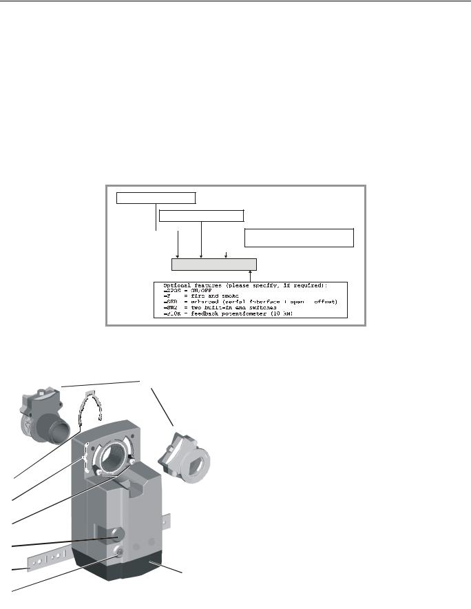
Product Identification System
N = non-spring return
S = spring return
20 = 20 Nm (177 lb-in)
34 = 34 Nm (300 lb-in)
010 = modulating
24 = 24 V floating+ON/OFF
230 = 230 V floating+ON/OFF
SmartAct N
 2 0
2 0
 2 3 0
2 3 0
 X
X
Fig. 1. Product Identification System
OPERATION / FUNCTIONS
|
|
|
|
Legend for Fig. 2: |
|
|
|
1 |
|
1 |
Self-centering shaft adapter |
|
|
|
2 |
Retainer clip |
|
|
|
|
|
||
|
|
|
|
3 |
Rotational angle scales (0...90° / 90...0°) |
|
|
|
|
4 |
Mechanical end limits (20 Nm [177 lb-in] models, only) |
|
|
|
|
5 |
Declutch button |
|
|
|
|
6 |
Anti-rotation bracket |
|
60 |
|
|
7 |
Rotation direction switch |
90 |
90 |
|
|
8 |
Access cover |
60 |
30 |
|
|
||
30 |
0 |
|
|
Contents of Package |
|
|
|
|
|||
0 |
|
|
|
||
2 |
|
|
|
The delivery package includes the actuator itself, parts 1 |
|
|
|
|
|
through 8 (see Fig. 2), the anti-rotation bracket screws, and |
|
3 |
|
|
|
the SM mounting plate and screws. |
|
|
|
|
Rotary Movement |
||
4 |
|
|
|
||
|
|
|
The rotation direction (clockwise or counterclockwise) can be |
||
|
|
|
|
||
5 |
|
|
|
selected using the rotation direction switch (see part 7 in Fig. |
|
|
|
|
2), thus eliminating the need to re-wire. To ensure tight |
||
6 |
|
|
|
closing of the dampers, the actuator has a total rotation stroke |
|
|
|
8 |
of 95°. |
||
|
|
|
As soon as operating power is applied, the actuator may start |
||
7 |
|
|
|
||
|
|
|
to run. When power is removed, the actuator remains in |
||
position. For actuator-controller wiring instructions, see section "Wiring" on page 7.
Fig. 2. Setting units and control elements
EN0B-0320GE51 R0409 |
2 |

SmartAct N2024 / N20230, N3424 / N34230
Rotation Direction Switch

 Dir
Dir
Service/Off

 Rev
Rev
Fig. 3. Rotation Direction Switch
•Dir ("
 ") is the default shipping position. When the rotation direction switch is set to this position, the actuator internally switches the rotation direction control signals as stated in section "Wiring Diagrams" on pages 5 and 6.
•"Service/Off": When the rotation direction switch is set to this position, all actuator rotary movement is cancelled and all control signals are ignored, thus enabling the actuator to be manually operated (see section "Manual Adjustment"). The user can then perform maintenance / commissioning without having to remove power from the actuator. To return to the control mode, simply move the rotation direction switch to its former setting.
•Rev ("
 "): When the rotation direction switch is set to this position, the actuator follows signals as stated in section "Wiring Diagrams" on pages 5 and 6.
Two-Position or Floating Control
The actuator is capable of being operated by either a twoposition (open/close) or (unless explicitly identified as a 2- POS model) a floating (three-wire) controller. Refer to wiring diagrams for correct connection.
Feedback Signal
Actuators equipped with a feedback potentiometer provide position feedback via the potentiometer resistance value (see Fig. 4).
P3
totally CCW |
totally CW |
|
= max. Ω |
= 0 Ω |
|
|
P2 |
10 kΩ |
totally CCW |
totally CW |
|
= 0 Ω |
= max. Ω |
|
|
P1 |
|
Fig. 4. Feedback signal settings
If, while the actuator is not rotating, the user declutches it and manually repositions the shaft adapter, the feedback signal will then follow the new position at which the shaft adapter has been left.
Position Indication
The hub adapter indicates the rotation angle position by means of the rotational angle scales (0...90° / 90...0°) provided in the actuator plate (see Fig. 5).
60 |
90 |
90 |
60 |
30 |
|
|
30 |
0 0
0
Fig. 5. Position indication
Manual Adjustment
IMPORTANT
To prevent equipment damage, you must remove power or set the rotation direction switch to the "Service/Off" position before manual adjustment.
After removing power or setting the rotation direction switch to the "Service/Off" position, the gear train can be disengaged using the declutch button, permitting the actuator shaft to be manually rotated to any position. The feedback signal will then follow the new position.
Limitation of Rotation Stroke
Two adjustable mechanical end limits (20 Nm [177 lb-in] models, only) are provided to limit the angle of rotation as desired (see Fig. 6).
ENSURE
PROPER
MESHING
OF TEETH
Fig. 6. Mechanical end limits
The mechanical end limits must be securely fastened in place as shown in Fig. 7. Specifically, it is important that they properly mesh with the rotational angle scales when the screws are tightened.
3 |
EN0B-0320GE51 R0409 |
 Loading...