

Page 1

HoneyWell N-1000 integration module
Settings guide
Page 2

1. List of terms used in HoneyWell N-1000 integration module Settings guide . . . . . . 3
2. Introduction into HoneyWell N-1000 integration module Settings guide . . . . . . . . 3
3. Supported hardware and licensing of the Honeywell N-1000 integration module . . 4
4. Setting up HoneyWell N-1000 integration module . . . . . . . . . . . . . . . . . . . . . . . 4
4.1 HoneyWell N-1000 integration module set up procedure . . . . . . . . . . . . . . . . 4
4.2 Setting up HoneyWell N-1000 ACS connection . . . . . . . . . . . . . . . . . . . . . . . 4
4.3 Setting up HoneyWell N-1000 controllers . . . . . . . . . . . . . . . . . . . . . . . . . . 5
4.4 Setting up HoneyWell N-1000 access points . . . . . . . . . . . . . . . . . . . . . . . . 8
4.4.1 Setting up HoneyWell N-1000 access point parameters . . . . . . . . . . . . . 8
4.4.2 Setting up HoneyWell N-1000 access point readers . . . . . . . . . . . . . . . . 9
4.5 Setting up HoneyWell N-1000 relays . . . . . . . . . . . . . . . . . . . . . . . . . . . . . . 10
4.5.1 Setting up HoneyWell exits . . . . . . . . . . . . . . . . . . . . . . . . . . . . . . . . . 10
4.5.1.1 Creation and setting up of exits . . . . . . . . . . . . . . . . . . . . . . . . . . 10
4.5.1.2 Creation and setting up of exit groups . . . . . . . . . . . . . . . . . . . . . . 11
4.5.2 Setting up HoneyWell N-1000 entrances . . . . . . . . . . . . . . . . . . . . . . . 12
4.5.2.1 Creation and setting up of entrances . . . . . . . . . . . . . . . . . . . . . . . 12
4.5.2.2 Creation and setting up of entrance groups . . . . . . . . . . . . . . . . . . 13
4.5.3 Setting up HoneyWell N-1000 relay interlock . . . . . . . . . . . . . . . . . . . . 14
4.6 Sending commands to HoneyWell N-1000 controller . . . . . . . . . . . . . . . . . . . 15
4.7 Configuration registration . . . . . . . . . . . . . . . . . . . . . . . . . . . . . . . . . . . . . 16
4.7.1 Registration of maximal configuration . . . . . . . . . . . . . . . . . . . . . . . . . 16
4.7.2 Registration of selected controller configuration . . . . . . . . . . . . . . . . . . 17
5. Working with HoneyWell N-1000 integration module . . . . . . . . . . . . . . . . . . . . . 17
5.1 General information about working with HoneyWell N-1000 module . . . . . . . . 17
5.2 Controlling HoneyWell N-1000 access point . . . . . . . . . . . . . . . . . . . . . . . . . 17
5.3 Controlling HoneyWell N-1000 entrances or entrance group . . . . . . . . . . . . . 17
5.4 Controlling HoneyWell N-1000 exits or exit group . . . . . . . . . . . . . . . . . . . . 18
Page 3

3
1.
2.
3.
1.
2.
List of terms used in HoneyWell N-1000
integration module Settings guide
Access is a movement of people, transport and other objects into (out of) premises, buildings, zones and territories.
Server is a computer with specified configuration of software packageServer Intellect .
Access card is a physical access identifier that is registered by the reared.
PIN code is an additional identification user characteristic that is typed from keyboard.
Controllers of access control system are electronic devices that are for control over access points.HoneyWell N-1000
Access control system (ACS) is a hardware-software complex that is used for access control.
Readers are electronic devices that are used for typing stored code from keyboard or for reading code information from
system keys (identifiers).
Access point is a place where there is access control. Door, turnstile, gates, barrier that are equipped with reader,
electromechanical lock and other access control devices, can be an access point.
Time schedule - a set of any number of time intervals during a day (24 hours) defined for several days (1 to 366), and the
time intervals during specific dates. Time schedule defines a schedule of access to the secured object.
Introduction into HoneyWell N-1000
integration module Settings guide
On the page:
Purpose of document
General information about «HoneyWell
N1000» integration module
Purpose of document
HoneyWell N-1000 integration module. Configuration and operation guide is a reference and information manual. It is
meant for configuration specialists and operators of module. This module is a part of access controlHoneyWell N-1000
system that is carried out on the basis of software package.ACFA Intellect
The following information is performed in this Guide:
General information about integration module;HoneyWell N-1000
Setting up integration module; HoneyWell N-1000
Working with integration module. HoneyWell N-1000
General information about «HoneyWell N1000» integration
module
HoneyWell N1000 integration module is a component of ACS that is carried out on the basis of softwareACFA Intellect
package and is for realization of the following functions:
HoneyWell N-1000 configuration ( Security is a manufacturer);ACS Honeywell
Interaction of with software package (configuration, monitoring, control). HoneyWell N-1000 ACS ACFA Intellect
N-1000-III and N-1000-IV TheseHoneyWell N-1000 ACS controllers are integrated into ACFA Intellect software package.
controllers are for ACS construction on the objects of medium size.
Technical features of N-1000-III and N-1000-IV controllers are given in the table.
Feature N-1000-III N-1000-IV
Number of supported readers /
keyboards
2/2 4/2 or 0/4
Maximum number of users, persons 5 000 (with 25 000 resolution) 5 000 (with 25 000 resolution)
Note.
Detailed information about HoneyWell N1000 ACS is given in official reference documentation for this system.
Page 4

4
1.
2.
1.
2.
3.
4.
5.
6.
Storage, events capacity 10 200 10 200
Number of relay outputs 4 4 (with 24 resolution)
Number of alarm inputs 16 (normally closed resistive / dead
contacts)
16 (normally closed / dead
contacts)
Before setting up integration module do the following:HoneyWell N-1000
Install hardware on secured object (see reference documentation for HoneyWell N-1000 ACS HoneyWell N-1000
).ACS
Connect to Server.HoneyWell N-1000 ACS
Supported hardware and licensing of the
Honeywell N-1000 integration module
Manufacturer Honeywell Systems Group
Video and Access Control Solutions
www.security.honeywell.com
Integration type Low-level protocol
Equipment connection RS-232
Supported equipment
Equipment Function Features
N-1000 Access controller 25000 or 5000 cards
16 alarm inputs
8 relays
63 time zones
8 programmable card formans
Protection
1 controller.
Setting up HoneyWell N-1000 integration
module
HoneyWell N-1000 integration module set up procedure
Setting up integration module is performed in the following succession:HoneyWell N-1000
Setting up connection of to ServerHoneyWell N-1000 ACS Intellect .
Setting up controllers.
Setting up access points.
Setting up entrances and exits.
Sending commands to controller.
Configuration registration.
Setting up HoneyWell N-1000 ACS connection
Setting up connection of to Server is carried out on the setting panel of HoneyWell N-1000 ACS Intellect HoneyWell
object. This object is created on the basis of object in tab of dialog box.N1000 Computer Hardware System setting
Page 5
5
1.
2.
3.
4.
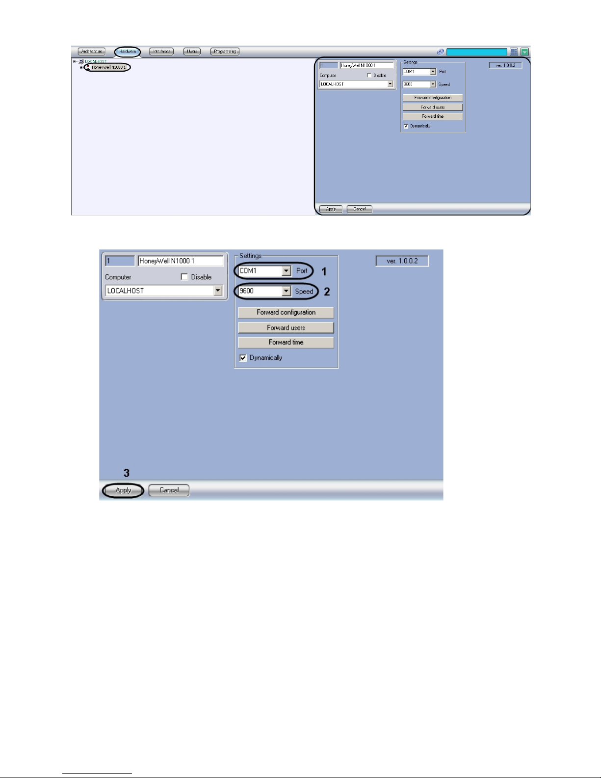
Setting up connection of to Server is carried out the following way:HoneyWell N-1000 ACS Intellect
Go to setting panel of object.HoneyWell N1000
From dropdown list select COM port of connection to Server ( ).Port HoneyWell N-1000 ACS Intellect 1
From dropdown list select speed of data transfer through COM port of connection to Speed HoneyWell N-1000 ACS
Server ( ).Intellect 2
Click ( ).Apply 3
Setting up connection of to Server is completed.HoneyWell N-1000 ACS Intellect
Setting up HoneyWell N-1000 controllers
Setting up controllers of is carried out on the setting panel of object. This object isHoneyWell N-1000 ACS N1000 panel
created on the basis of object in tab of dialog box.HoneyWell N1000 Hardware System setting
Page 6
6
1.
2.
a.
b.
3.
4.
5.
a.
b.
6.
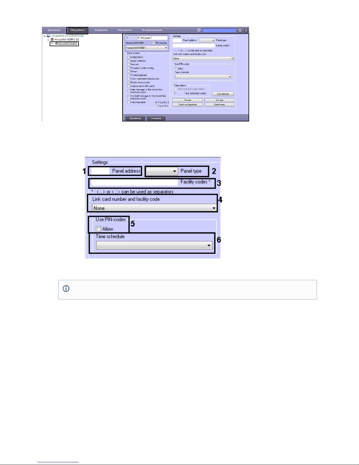
Setting up controller of is carried out the following way:HoneyWell N-1000 ACS
Go to setting panel of object.N1000 panel
Set connection parameters of controller:
Set controller address in ( ).Panel address 1
From dropdown list select type of connected controller ( ).Panel type 2
In set codes used by organization (facility codes) ( ).Facility codes 3
Select format of linking access card number and organization code (facility code) from the corresponding dropdown
list ( ).4
Set up user access through PIN code:
Set checkbox if it’s necessary to ask PIN code of the user while giving the access ( ).Allow 5
From the corresponding dropdown list select time zone during which it’s necessary to ask PIN code of the
user while giving the access ( ).6
Set up basic controller options:
Note.
If there is no need to link access card number and organization code it’s necessary to set value.None
Page 7

7
a.
b.
c.
d.
e.
f.
g.
h.
i.
j.
k.
l.
7.
If it’s necessary to control double-pass set the corresponding checkbox ( ).1
Set checkbox if there is no need to store user violations ( ).Ignore violations 2
Set checkbox if it’s necessary to ask access while passing to exit ( ).Free exit 3
Set checkbox if it’s necessary to read card code permanently and regardless ofPermanent code-reading
exit impulse duration ( ).4
Set checkbox if it’s necessary to create groups of exits ( ).Groups 5
If 11-wires keyboard is used in controller it’s necessary to set the corresponding checkbox ( ).6
Set checkbox if it’s necessary to transmit and commands ( ).In/out commands transmission In Out 7
If it’s necessary to use reader reverse color set the corresponding checkbox ( ).8
If it’s necessary to use ABA-card long format set the corresponding checkbox ( ).9
If it’s necessary to create alarm message on exiting the closed time zone set the corresponding checkbox (1
).0
If it’s necessary to create standard message on exiting the closed time zone set the corresponding checkbox
( ).11
If it’s necessary to switch entrances set the corresponding checkbox and select necessary type ( ).12
Click and set up used formats of access cards of Wiegand type. After setting click in orderОК
to save formats.
Note.
ABA is the MSR ABA TK2 emulation interface for magnetic access cards.
Note.
3 formats card of Wiegand type are set on default: 26-,32- and 34-bit.
Page 8

8
8.
1.
2.
1.
Reader / Number of bit in access card Access card format
CR-1 Wiegand Card Swipe / 26 bit-generic 26-S-1-D-1-B1-B2-B3-B4
NR-1 Magstripe, NR5 / 32 bit 32-S-0-D-0-B1-B2-B3-B4
HID / 34 bit 34-S-1-D-1-B1-B2-B3-B4
CI-1 Wiegand Card Insert / 26 bit 26-I-1-D-1-B1-B2-B3-B4
PR-1-280 Cotag Proximity / 32 bit 32-S-0-D-0-B1-B2-B3-B4
HG-1 Hand Geometry / 32 bit 32-S-0-D-0-B1-B2-B3-B4
5 Conductor Keypad / 32 bit 32-S-0-D-0-B1-B2-B3-B4
Dorado Magstripe Cards / 34 bit 34-S-1-D-0-B1-B2-B3-B4
Sielox Wiegand Cards / 34 bit 34-S-1-D-1-B1-B2-B3-B4
Sielox Proximity Cards / 32 bit 32-S-0-D-0-B1-B2-B3-B4
On setting panel of object click to save changes.N1000 panel Apply
Setting up controller of is completed.HoneyWell N-1000 ACS
Setting up HoneyWell N-1000 access points
Setting up access points of controller is carried out the following way:HoneyWell N-1000 ACS
Setting up access point parameters.
Setting up access point readers.
Setting up HoneyWell N-1000 access point parameters
Setting up access point parameters is carried out on setting panel of object. This object is created on theN1000 door
basis of object on tab of dialog box.N1000 panel Hardware System settings
Setting up access point parameters is carried out the following way:
Go to setting panel of object.N1000 door
Page 9

9
2.
3.
4.
5.
1.
In set access point address ( ).Door number 1
From dropdown list select object that corresponds to the territory located on the side of reader’sExit: Region
entrance ( ).2
From dropdown list select object that corresponds to the territory located on the side of reader’sEnter: Region
exit ( ).3
Click in order to save changes ( ).Apply 4
Setting up access point parameters is completed.
Setting up HoneyWell N-1000 access point readers
Setting up access point readers is carried out on setting panel of object. This object is created on the basisN1000 reader
of object on tab of dialog box.N1000 door Hardware System settings
Setting up access point readers is carried out the following way:
Go to setting panel of object.N1000 reader
Page 10

10
2.
3.
4.
5.
6.
7.
8.
9.
Set reader address in the corresponding field ( ).1
Select reader type from dropdown list: reader only, reader with keyboard, keyboard only ( ).Type 2
If keyboard is used set its address in the corresponding field ( ).7
From dropdown list select reader operation mode: entrance or exit ( ).Direction 3
In setting group deselect checkbox and select object corresponding to relay or relay groupActivization Default
(both entrance and exit) for activation after passing through this reader ( ).4
In field set a number that corresponds to the number of failed access attempts after whichCheating threshold
there is activation of specified device ( ).5
From and dropdown lists select object corresponding to relay or relay group (both entrance and exit)Type Name
for activation after attempt to select access card ( ).6
Click in order to save changes ( ).Apply 8
Setting up access point reader is completed.
Setting up HoneyWell N-1000 relays
Setting up HoneyWell exits
Creation and setting up of exits
Setting up exits is carried out on setting panel of object. This object is created on the basis of N1000 exit N1000 panel
object on tab of dialog box.Hardware System settings
Note.
If checkbox is set then there is activation of device that is set on default in equipment settings.Default
Page 11

11
1.
2.
3.
a.
b.
4.
5.
1.
Setting up exits is carried out the following way:
Go to setting panel of object.N1000 exit
Set address of exit in ( ).Exit address 1
In setting group set parameters of exit impulse:Impulse
In field set the period during which power supply (impulse) will be given to exit ( );Duration 2
From the corresponding dropdown list select time zone during which power supply will be given to exit
automatically ( ).3
If it’s necessary set time zone during which there will be no interactions connected with this exit ( ).4
Click in order to save changes ( ).Apply 5
Setting up exit is completed.
Creation and setting up of exit groups
Setting up exit groups is carried out on setting panel of object. This object is created on the basis of N1000 group N100
object on tab of dialog box.0 panel Hardware System settings
Setting up exit groups is carried out the following way:
Go to setting panel of object.N1000 group
Page 12

12
1.
2.
3.
4.
5.
6.
7.
8.
9.
10.
1.
Set address of exit group in the corresponding field ( ).1
Set checkboxes opposite those exits that should be in the group ( ).2
In setting group set parameters of exit group impulse:Impulse
In field set the period during which power supply (impulse) will be given to exit group ( );Duration 3
From the corresponding dropdown list select time zone during which power supply will be given to exit group
automatically ( ).4
If it’s necessary set time zone during which there will be no interactions connected with this exit group ( ).5
If it’s necessary select warning group from the corresponding dropdown list ( ).6
If it’s necessary set this group as a special group for exit: set checkbox and select necessary object from theAllow
list ( ).7
Click in order to save changes ( ).Apply 8
Setting up exit groups is completed.
Setting up HoneyWell N-1000 entrances
Creation and setting up of entrances
Setting up entrances is carried out on setting panel of object. This object is created on the basis of N1000 entrance N10
object on tab of dialog box.00 panel Hardware System settings
Setting up entrances is carried out the following way:
Go to setting panel of object.N1000 entrance
Page 13

13
1.
2.
3.
4.
a.
b.
5.
6.
7.
8.
9.
10.
11.
12.
13.
Set entrance address in ( ).Address 1
From dropdown list select type of entrance ( ).Entrance 2
In setting group set parameters of entrances disconnection:Bypass
In field set period during which entrance will be disconnected ( );Duration 3
From corresponding dropdown list select time zone during which entrance disconnects automatically ( ).4
Set delay of bounce of entrance contacts (in seconds) in the corresponding field ( ).5
If it’s necessary to switch on function set checkbox and select necessary object from and Auto lock Allow Type N
dropdown lists ( ).ame 6
If it’s necessary set time zone during which there will be no interactions connected with this entrance ( ).7
If it’s necessary to require confirmation while activating entrance then set checkbox, set period of timeAllow
during which the confirmation should be received and select time zone during which the confirmation will be
required ( ).8
If it’s necessary to activate buffering mode then set checkbox and select time zone during which this modeAllow
will be active ( ).9
If it’s necessary to disable alarm messages then set checkbox and select time zone during which there willDisable
be the prohibition ( ).10
Set checkbox if it’s necessary to substitute state with and viceAlarm/normal state inversion Alarm Normal
versa ( ).11
If it’s necessary to limit incoming messages by damage-only messages then set the corresponding checkbox ( ).12
Click in order to save changes ( ).Apply 13
Setting up entrance is completed.
Creation and setting up of entrance groups
Setting up entrance groups is carried out on setting panel of object. This object is created on the basis of N1000 zone N1
object on tab of dialog box.000 panel Hardware System settings
Setting up entrance groups is carried out the following way:
Page 14

14
1.
2.
3.
4.
a.
b.
5.
6.
1.
Go to setting panel of object.N1000 zone
Set address of entrance group in the corresponding field ( ).1
Set checkboxes opposite those entrances that should be in the group ( ).2
In setting group set parameters of disconnection entrance group:Bypass
In field set period during which entrances of the group will be disconnected ( );Duration 3
From corresponding dropdown list select time zone during which entrances of the group disconnect
automatically ( ).4
If it’s necessary set time zone during which there will be no interactions connected with this group of entrances ( ).5
Click in order to save changes ( ).Apply 6
Setting up of entrances groups is completed.
Setting up HoneyWell N-1000 relay interlock
Setting up relay or relay groups interlocks is carried out on setting panel of object. This object isN1000 interaction
created on the basis of object on tab of dialog box.N1000 panel Hardware System settings
Setting up relay or relay groups interlocks is carried out the following way:
Go to setting panel of object.N1000 interaction
Page 15

15
1.
2.
3.
4.
5.
6.
1.
In parameter group from and dropdown lists select action object that corresponds toInitiator object Type Name
relay or relay group. Activating and deactivating this object you activate specified action of action object ( ).1
In parameter group from and dropdown lists select action object that correspondsDependent object Type Name
to relay or relay group. Activating and deactivating this object you activate specified action of initiator object ( ).2
From the corresponding dropdown list select action that should be done when initiator activated ( ).3
From the corresponding dropdown list select action that should be done when initiator deactivated ( ).4
Click in order to save changes ( ).Apply 5
Setting up interlock is completed.
Sending commands to HoneyWell N-1000 controller
Sending commands to controller is carried out from setting panel of object. This object is created on theN1000 command
basis of object on tab of dialog box.N1000 panel Hardware System settings
Sending commands to controller is carried out the following way:
Go to setting panel of object.N1000 command
Page 16

16
2.
3.
1.
2.
3.
4.
Set command in the line ( ).1
Click ( ).Send command 2
Sending command to controller is completed.
Configuration registration
Registration of maximal configuration
Registration of maximal configuration is carried out on setting panel of object the following way:HoneyWell N1000
To start registration of system configuration click ( ).Forward configuration 1
To register access cards of users click ( ).Forward users 2
To synchronize time click ( ).Forward time 3
Set checkbox if it’s necessary to register configuration changes automatically ( ).Dynamically 4
Note.
Description of commands is given in official reference documentation for HoneyWell N1000 system.
Page 17

17
5.
1.
2.
3.
1.
2.
3.
4.
Click in order to save changes ( ).Apply 5
Registration of maximal configuration is completed.
Registration of selected controller configuration
Registration of selected controller configuration is carried out on setting panel of object corresponding toN1000 panel
required controller. It is carried out the following way:
To register controller configuration click ( ).Forward configuration 1
To register access cards of users click ( ).Forward users 3
To synchronize time click ( ).Set time 4
Registration of controller configuration is completed.
Working with HoneyWell N-1000 integration
module
General information about working with HoneyWell
N-1000 module
The following interface objects are used for working with integration module:HoneyWell N-1000
Card;
Event protocol;
Visitor Management System;
Time and Attendance.
Information about these interface objects’ configuration is given Intellect Software package: Administrator's Guide, Visitor
and .Management System Module Settings and Operation Guide Time and Attendance Module Settings and Operation Guide
Working with interface objects is given in details in .Intellect Software package: Operator's Guide
Controlling HoneyWell N-1000 access point
Controlling access point of is carried out in interactive box using feature menu of HoneyWell N-1000 ACS Card N1000
object.door
Description of feature menu commands of object is given in the table.N1000 door
Command of feature menu Functionality
Open the door for time Open passage through access point for some time
Close the door Close passage through access point
Open the door Open passage through access point
Controlling HoneyWell N-1000 entrances or entrance
group
Controlling entrances or entrance group of is carried out in interactive box using featureHoneyWell N-1000 ACS Card
menu of or objects.N1000 entrance N1000 zone
Note.
To restart controller click ( )Restart 2 .
Page 18

18
Description of feature menu commands of and objects is given in the table.N1000 entrance N1000 zone
Command of feature menu Functionality
Remove all options Remove all options of entrance (entrance group)
Cancel TZ control Cancel controlling entrance (entrance group) using TZ
Accept alarm Take status and switch entrance (all entrances of the group) into normal stateAlarm
Remove bypass Remove bypass of entrance (all entrances of the group)
Cancel interactions Cancel interactions connected with this entrance (entrance group)
Bypass Enable bypass of entrance (entrance group)
Connection support Enable connection support of entrance (entrance group)
Repair TZ control Repair controlling entrance (entrance group) using TZ
Bypass for time Enable bypass of entrance (entrance group) for some time
Controlling HoneyWell N-1000 exits or exit group
Controlling exits or exit group of is carried out in interactive box using feature menu of HoneyWell N-1000 ACS Card N100
or objects.0 exit N1000 group
Description of feature menu commands of and objects is given in the table.N1000 exit N1000 group
Command of feature menu Functionality
Remove all options Remove all options of exit (exit group)
Cancel TZ control Cancel controlling exit (exit group) using TZ
Disable Disable exit (all exits of the group)
Cancel interactions Cancel interactions connected with this exit (exit group)
Enable Enable exit (all exits of the group)
Connection support Enable connection support of exit (exit group)
Page 19

19
Repair TZ control Repair controlling exit (exit group) using TZ
Send impulse Send impulse to exit (all exits of the group)
 Loading...