

Page 1
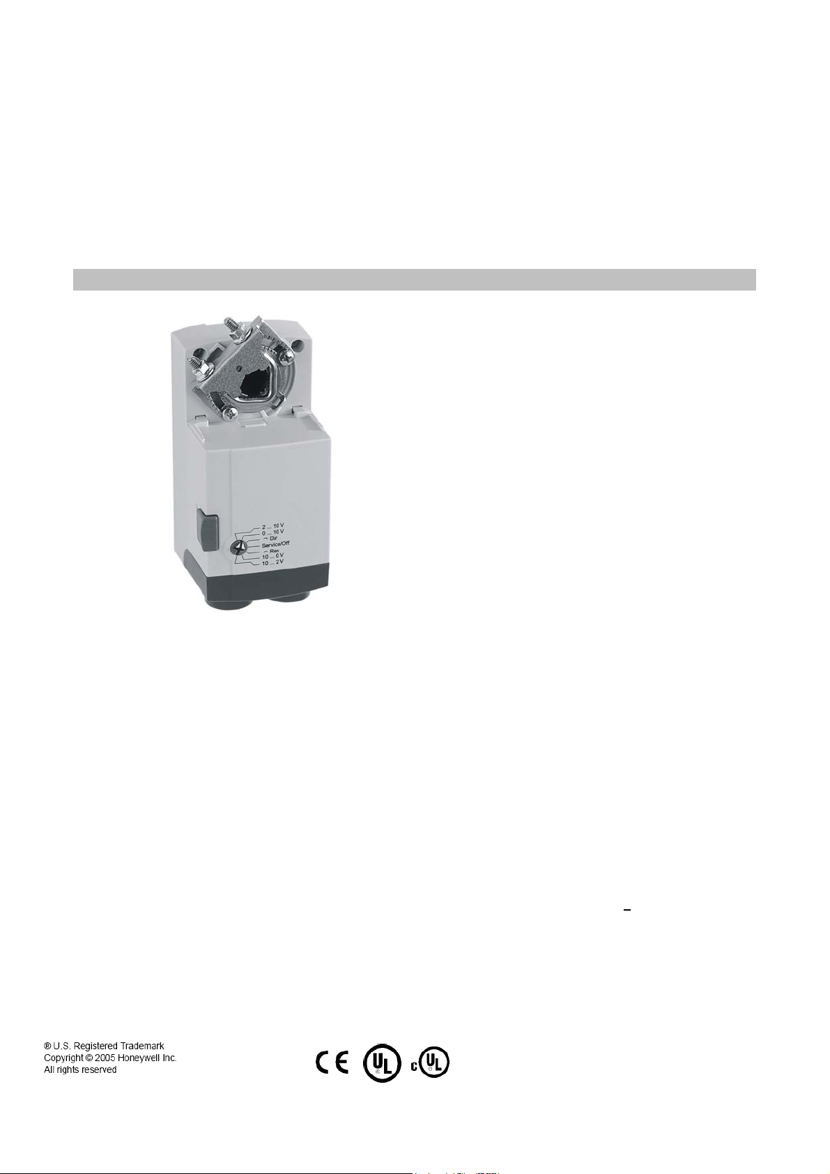
N05, N10 SERIES
NON-SPRING RETURN DIRECT-COUPLED DAMPER ACTUATORS FOR
MODULATING AND FLOATING CONTROL
PRODUCT DATA
SPECIFICATIONS
Supply voltage 24 Vac/dc -15%/+20%, 50/60 Hz
Nominal voltage 24 Vac/dc, 50/60 Hz
All values stated hereinafter apply to operation under
nominal voltage conditions.
Power consumption
CN7505 5 VA / 2 W
CN7510 5 VA / 2 W
Control signal
Modulating (0)2...10 Vdc
Floating/2-Position 24 Vac/dc
Ambient limits
Ambient operating limits -5...+140 °F (20...+60 °C)
Ambient storage limits -22...+176 °F (-30...+80 °C)
GENERAL
This non-spring return direct-coupled damper actuator
provides modulating and floating/2-position control for:
• air dampers,
• VAV units,
• air handlers,
• ventilation flaps,
• louvers, and
• reliable control for air damper applications with up to 10 sq ft
/ 44 lb-in. (5 Nm) and 20 sq ft / 88 lb-in. (10 Nm) (seal- less
damper blades; air friction-dependent).
FEATURES
Relative humidity 5...95%, non-condensing
Safety
Protection standard IP54
Protection class II as per EN 60730-1
Overvoltage category II
Lifetime
Full strokes 60000
Repositions 1.5 million
Mounting
Round damper shaft 3/8 in…5/8 in.
Square damper shaft 1/4 in…1/2 in.; 45° steps
Shaft length min. 1-5/8 in.
End switches (when included)
Rating Class II
Triggering points 5° / 85°
Torque rating 44 lb-in. (5Nm) / 88 lb-in. (10Nm)
• Declutch for manual adjustment
• Adjustable mechanical end limits
• Removable access cover for direct wiring
• Mountable in any orientation
• Function selection switch for selecting modulating or
floating/2-position control
Rotation stroke 95° +
Dimensions see “Dimensions” on page 8
Weight (without cables) 1.0 lbs.
Noise rating 35 dB(A) max. at 1 m
1
3°
CN0B-0545CH33 R0805
63-6233T
Page 2
N05,N10 SERIES DAMPER ACTUATORS FOR MODULATING AND FLOATING CONTROL
PRODUCT IDENTIFICATION SYSTEM
C-Electrical Motor
N-Fail Safe Function (Non-Spring Return)
XX-System Controlled Numbers
C N 75 10 A 2 0 XX
61-24V Floating Control
75-24V Modulating Control
05-44 lb-in. (5 Nm)
10-88 lb-in. (10 Nm)
A-Standard Model
1-No Feedback
2-Voltage Feedback Signal
0-No Internal Auxiliary Switches
2-Two Internal Auxiliary Switches
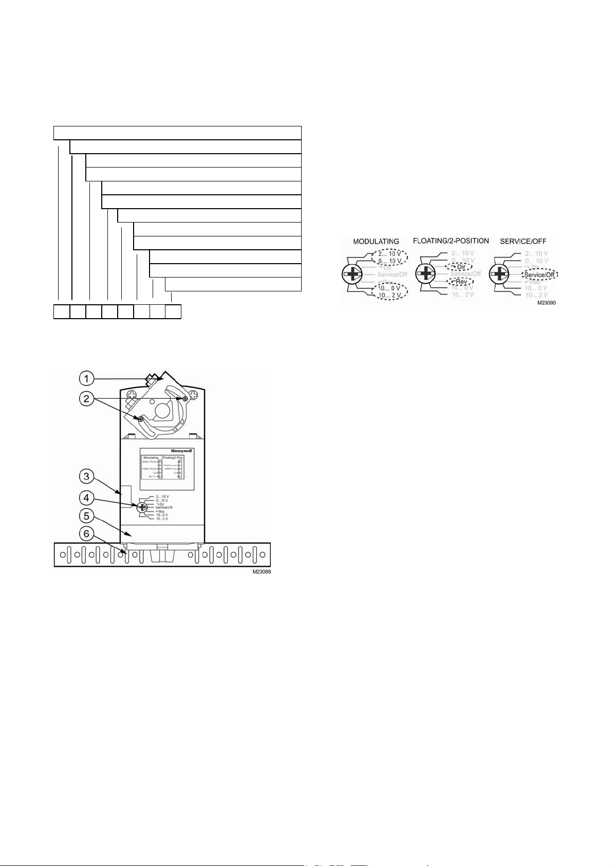
Contents of Package
The delivery package includes the actuator, parts 1 through 6
(see Fig. 1), plus two cable grommets and a spare cable
grommet.
RUN MODES
The function selection switch (see Fig. 2) can be used to place
the actuator into any one of two different modes:
• Service/Off; or
• the floating/2-position run mode (“Dir” for CCW-closing
dampers or “Rev” for CW-closing dampers).
• the modulating run modle.
Fig. 2. Function selection switch
BASIC FEATURES
Fig. 1. Setting units and control elements
Legend for Fig. 1:
1) Universal shaft adapter
2) Mechanical end limits (manually adjustable)
3) Declutch button
4) Function selection switch
5) Removable access cover
6) Anti-rotation bracket
63-6233T
CN0B-0545CH33 R0805
Power-Off Behavior
If power is removed, the shaft adapter remains in position.
Service/Off
If the function selection switch is set to the “Service/Off” position,
then all rotary movement is cancelled, and all control signals are
ignored, thus allowing the actuator to be manually operated
safely.
Floating/2-Position Run Mode
Without Feedback Signal
If, however, the function selection switch has been set to one of
the two floating/2-position control settings - but the actuator has
not been wired for a feedback signal (see Fig. 12 and Fig. 13) then as soon as operating power is applied, the shaft adapter will
run according to the control signals applied.
With Feedback Signal
If the function selection switch has been set to one of the two
floating/2-position control settings - and if the actuator has been
wired for a feedback signal (see Fig. 12 and Fig. 13) - then as
soon as operating power is applied, the shaft adapter will likewise
run first completely counterclockwise and then completely
clockwise (see also section “Adaption”), after which it will run
according to the control signals applied.
Modulating Run Mode
If the function selection switch has been set to one of the four
modulating control settings - and if the actuator is wired
correspondingly (see Fig. 10) - then as soon as operating power
is applied, the shaft adapter will run first completely
counterclockwise and then completely clockwise (see also
section “Adaption”), after which it will run according to the control
signals applied.
2
Page 3
N05,N10 SERIES DAMPER ACTUATORS FOR MODULATING AND FLOATING CONTROL
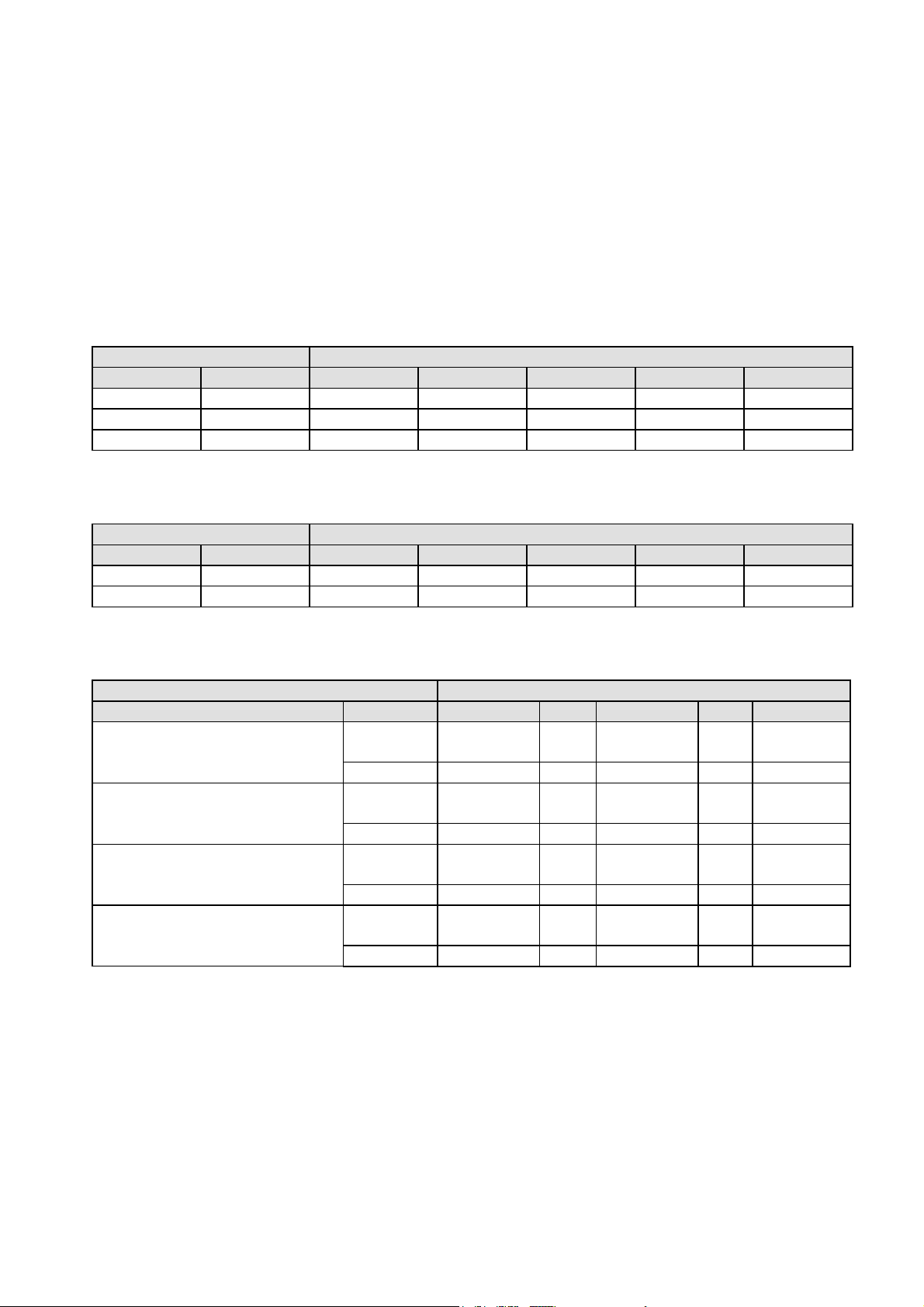
Table 1 describes, for the floating mode, the shaft adapter
behavior (“stops,” rotates “CCW,” or rotates “CW”) in dependence
upon the control signals applied to terminals 3 and 4 and upon
the function selection switch setting.
Table 2 describes, for the 2-position mode, the shaft adapter
behavior (“stops,” rotates “CCW,” or rotates “CW”) in dependence
upon the control signals applied to terminals 3 and 4 and upon
the function selection switch setting.
open open -- stops stops stops --
open 24 Vac/dc -- CCW stops CW --
24 Vac open -- CW stops CCW --
24 Vac open -- CW stops CCW --
24 Vac 24 Vac/dc -- CCW stops CW --
control signal at switch settings
terminal 3 terminal 4 0[2]...10V Dir Service/Off Rev 10...0[2] V
control signal at switch settings
terminal 3 terminal 4 0[2]...10V Dir Service/Off Rev 10...0[2] V
Table 1. Shaft adapter behavior in the floating mode
Table 2. Shaft adapter behavior in the 2-position mode
Table 3 describes, for the modulating mode, the shaft adapter
behavior (“stops,” rotates “totally CCW,” rotates “totally CW,” runs
to “proportional” position, or runs to “50%” of max. stroke) in
dependence upon the control signals applied to terminals 3 and 4
and upon the function selection switch setting.
open
< min control signal plus 0.24 V
between min. control signal plus 0.24 V
and max. control signal minus 0.24
> max. control signal minus 0.24 V
control signal at switch settings
terminal 3 terminal 4 0[2]...10V Dir Service/Off Rev 10...0[2] V
Table 3. Shaft adapter behavior in the modulating mode
open totally CCW -- stop -- totally CCW
24 Vac/dc 50% -- stop -- 50%
open totally CCW -- stop -- totally CW
24 Vac/dc 50% -- stop -- 50%
open proportional -- stop -- proportional
24 Vac/dc 50% -- stop -- 50%
open totally CW -- stop -- totally CCW
24 Vac/dc 50% -- stop -- 50%
63-6233T
3
CN0B-0545CH33 R0805
Page 4

N05,N10 SERIES DAMPER ACTUATORS FOR MODULATING AND FLOATING CONTROL
Fig 5. Adaption (function selection switch set to
Fig 3. Final shaft adapter position in dependence upon
control signal (example function selection switch setting
of 0...10 V)
Adaption will be carried out whenever the actuator is in the
modulating mode or the floating plus feedback mode or the 2position plus feedback mode and
• the user powers up (from a totally powerless condition) the
actuator; or
• the user sets the function selection switch to the “Service/
Off” setting for at least 2 seconds and then back to its previous
setting; or
• the control signal's value rises up into the upper dead band
(i.e. to more than the max. control signal minus 0.24 V) or
drops down into the lower dead band (i.e. to less than the min.
control signal plus 0.24 V), after which the shaft adapter must
then remain at the respective (upper or lower) mechanical end
limit for at least 3 seconds. However, in this case, the actuator
will then recognize the position of only the respective (upper or
lower) mechanical end limit.
0...10 V)
Fig 4. Feedback signal in dependence upon current
position of shaft adapter (example function selection
switch setting of 0...10 V)
Adaption
Adaption is a function in which the actuator re-maps its feedback
signal and control signal in accordance with repositioned
mechanical end limits (see also Fig. 6) and thus recognizes their
new positions
63-6233T
CN0B-0545CH33 R0805
Overriding
An override is a condition in which a 24 V signal is applied to
terminal 4 of an actuator in the modulating mode, thus causing
the actuator to ignore the control signal at terminal 3, whereupon
it will instead move to a position of 50% of its maximum stroke
(see Table 3).
Feedback
If correspondingly wired (see Fig. 10, Fig. 11 and Fig. 12), the
actuator provides, via terminal 5, a feedback signal proportional
to the actual position of the shaft adapter.
MANUAL ADJUSTMENT
IMPORTANT
To prevent equipment damage, you must remove power
or set the function selection switch to the
“Service/Off” position before manual adjustment.
4
Page 5

After removing power or setting the function selection switch to
the “Service/Off” position, the gear train can be disengaged using
the declutch button, permitting the shaft adapter to be manually
rotated to any position. If you have wired the actuator for
feedback signal, then, after adaption, the feedback signal will
follow the new position.
N05,N10 SERIES DAMPER ACTUATORS FOR MODULATING AND FLOATING CONTROL
Limitation of Rotation Stroke
Two adjustable mechanical end limits are provided to limit the
angle of rotation as desired (see Fig. 7). The mechanical end
limits must be securely fastened in place.
INSTALLATION
To avoid personal injury (electrical shock) and to
prevent equipment damage, before installation, you
must remove power.
These actuators are designed for single-point mounting.
Mounting Instructions
All information and steps are included in the Installation
Instructions (Product Literature No. 62-0224) supplied with each
actuator.
Mounting Position
The actuators can be mounted in any position (IP54 is dependent
upon orientation; see Fig. 9). Choose a mounting position
permitting easy access to cables and controls.
Fig 6. Mechanical end limits
To ensure tight closing of the dampers, the shaft adapter has a
total rotation stroke of 95°.
After adjusting the mechanical end limits, the user should trigger
adaption (see section “Adaption”).
INTERNAL END SWITCHES
The internal end switches “A” and “B” are changeover switches
which are activated when the shaft adapter moves past a position
of 5° and 85°, respectively (see also Table 5).
Fig 7. Internal end switch triggering points
Fig 8. Mounting for IP54
NOTE: Further, in order to guarantee IP54, only original
Honeywell grommets may be used.
Anti-Rotation Bracket and Screws
If the actuator is to be mounted directly on a damper shaft, use
the anti-rotation bracket and screws included in the delivery
package. The min. distance between the center of the damper
shaft and the middle of the anti-rotation bracket is 3.35 in.; a max.
of 4.25 in. is allowed (see also Fig 14).
Depending upon the specifics of your mounting site, the actuator
may shift in position slightly while tightening the screws at the top
of the shaft adapter. The anti-rotation bracket features a T-piece
with a 5-mm-long shank to accommodate for this movement. It is
important to ensure that this play is not impeded.
Universal Shaft Adapter
The universal shaft adapter can be used for shafts of various
diameters and shapes (round: 3/8...5/8 in. and square:
1/4...1/2 in.).
5
CN0B-0545CH33 R0805
63-6233T
Page 6

N05,N10 SERIES DAMPER ACTUATORS FOR MODULATING AND FLOATING CONTROL
Wiring Diagrams
WIRING
To avoid personal injury (electrical shock) and to
prevent equipment damage, before wiring, you must
remove power.
Access Cover
IMPORTANT
Once the access cover has been removed, please take
care to avoid damaging any of the parts now accessible.
The access cover can be unscrewed and removed in order to
gain access to the terminal block(s) and perform wiring.
Fig 11. CN7505/CN7510 (floating mode)
Wiring Diagrams
Fig 10. CN7505/CN7510 (modulating mode)
63-6233T
CN0B-0545CH33 R0805
Fig 9. Access Cover
Fig 12. CN7505/CN7510 (2-position mode)
Fig. 2. End switches
NOTE: Both of the internal end switches must be connected to
the same power source.
Table 4 and Table 5 summarize the information presented in the
preceding wiring diagrams.
6
Page 7

N05,N10 SERIES DAMPER ACTUATORS FOR MODULATING AND FLOATING CONTROL
terminal mode
NOTE: All cables connected to these terminals must be equipped with spark suppression.
1 24 V ~/+ (power) unused or (with feedback)
2 common ~/- common ~/- common ~/-
3 0[2]...10 V (control) 24 V ~/+ (control signal) 24 V ~/+ (control signal)
4 24 V ~/+ (override) 24 V ~/+ (control signal) 24 V ~/+ (control signal)
5 0[2]...10 V (feedback) unused or (with feedback)
terminal type of switch
S1 common lead for switches A and B
S2, S3 change-over switch A (S1/S2 opens and S1/S3 closes when shaft adapter moves CW past 5°; reverts to
original state when shaft adapter moves CCW past 5°).
S5, S6 change-over switch B (S1/S5 opens and S1/S6 closes when shaft adapter moves CW past 85°; reverts to
original state when shaft adapter moves CCW past 85°).
modulating floating 2-position
Table 4. Signals at terminals
Table 5. Internal end switches
24 V ~/+ (power)
0...10 V
unused or (with feedback)
24 V ~/+ (power)
unused or (with feedback)
0...10 V
7
CN0B-0545CH33 R0805
63-6233T
Page 8

N05,N10 SERIES DAMPER ACTUATORS FOR MODULATING AND FLOATING CONTROL
DIMENSIONS
Fig. 2. Dimensions (in in.)
Automation and Control Solutions
Honeywell International Inc. Honeywell (Tianjin) Limited
1985 Douglas Drive North 66, BaiHe Road, TEDA
Golden Valley, MN 55422 Tianjin, 300457,P.R.C.
Printed in China. on recycled
paper containing at least 10%
post-consumer paper fibers.
Honeywell
 Loading...