

Page 1
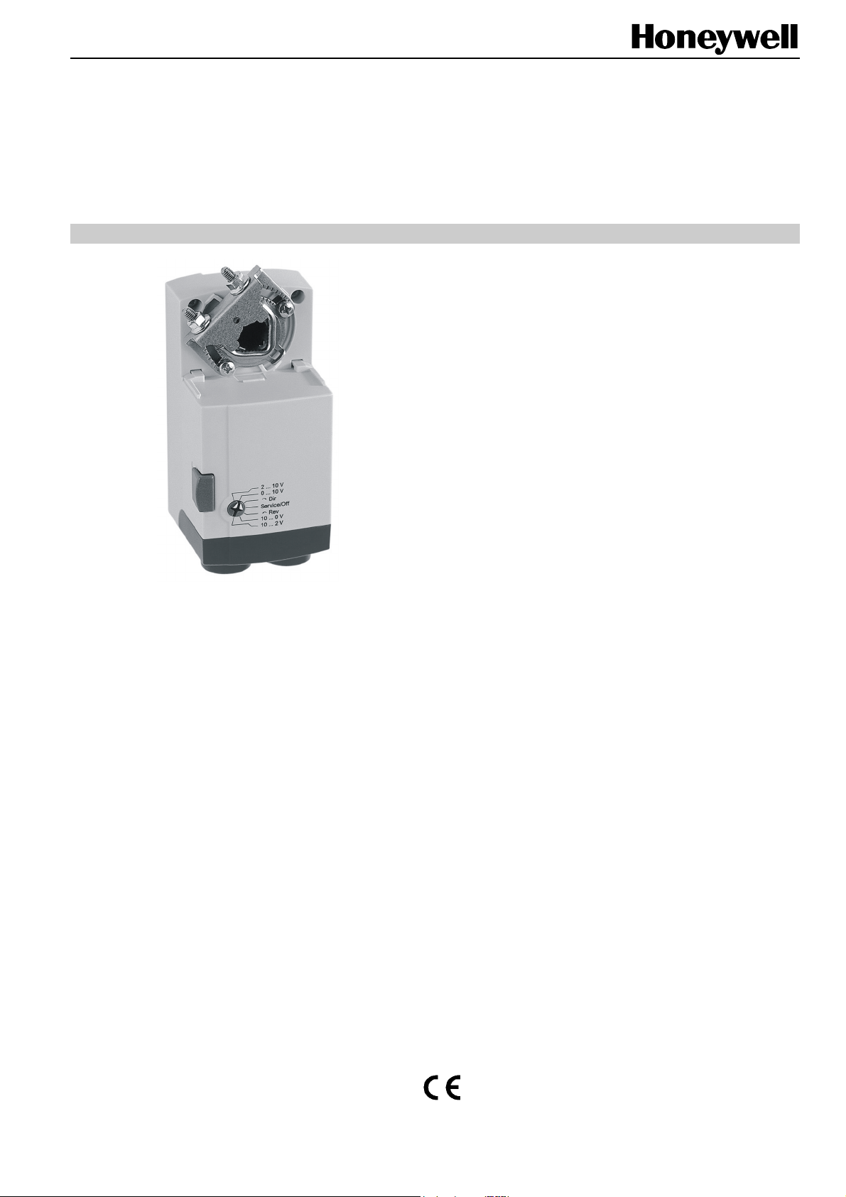
N05010/N10010
NON-SPRING RETURN DIRECT-COUPLED DAMPER ACTUATORS FOR
MODULATING AND FLOATING / 2-POSITION CONTROL
PRODUCT DATA
SPECIFICATIONS
Supply voltage 24 Vac/dc -15%/+20%, 50/60 Hz
Nominal voltage 24 Vac/dc, 50/60 Hz
All values stated hereinafter apply to operation under
nominal voltage conditions.
Power consumption
N05010 5 VA / 2 W
N10010 5 VA / 2 W
Control signal
Modulating 0...10 V
Floating/2-Position 24 Vac/dc
Ambient limits
Ambient operating limits -20...+60 °C (-5...+140 °F)
Ambient storage limits -30...+80 °C (-22...+176 °F)
Relative humidity 5...95%, non-condensing
Safety
GENERAL
This non-spring return direct-coupled damper actuator
provides modulating and floating/2-position control for:
• air dampers,
• VAV units,
• air handlers,
• ventilation flaps,
• louvers, and
• reliable control for air damper applications with up to 1 m
/ (5 Nm) and 2 m
friction-dependent).
2
(10 Nm) (seal-less damper blades; air
FEATURES
• Declutch for manual adjustment
• Adjustable mechanical end limits
• Removable access cover for direct wiring
• Mountable in any orientation
• Function selection switch for selecting modulating or
floating/2-position control
Protection standard IP54
Protection class II as per EN 60730-1
Overvoltage category II
Lifetime
Full strokes 60000
Repositions 1.5 million
Mounting
Round damper shaft 8...16 mm
Square damper shaft 6...13 mm; 45° steps
Shaft length min. 41 mm
2
End switches (when included)
Rating 5 A (resistive), 3 A (inductive)
Triggering points 5° / 85°
Torque rating 5 Nm / 10 Nm
Runtime for 90°
mod. (dc / 50/60 Hz ac) 90 sec
floating (dc / 60 Hz ac) 90 sec
floating (50 Hz ac) 110 sec
Rotation stroke 95° ± 3°
Dimensions see "Dimensions" on page 8
Weight (without cables) 450 g
Noise rating 35 dB(A) max. at 1 m
® U.S. Registered Trademark EN0B-0478GE51 R0408
Copyright © 2008 Honeywell Inc. • All rights reserved
Page 2
N05010/N10010 DAMPER ACTUATORS FOR MODULATING AND FLOATING/2-POSITION CONTROL
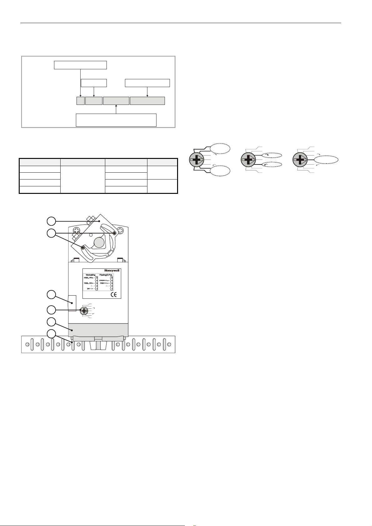
PRODUCT IDENTIFICATION SYSTEM
Contents of Package
The delivery package includes the actuator, parts 1 through 6
N = non-spring return
S = spring return
(see Fig. 2), plus two cable grommets and a spare cable
grommet.
05 = 5 Nm
10 = 10 Nm
equipped with two
end switches
RUN MODES
The function selection switch (see Fig. 3) can be used to
W
SmartAct
N
5
0
0-0
010 = modulating + floating
24 = 24 V floating + ON/OFF
230 = 230 V ON/OFF
S
+ ON/OFF
21
Fig. 1. Product Identification System
place the actuator into any one of three different modes:
• Service/Off;
• the floating/2-position run mode ("Dir" for CCW-closing
dampers or "Rev" for CW-closing dampers); and
• the modulating run mode.
modulating
MODELS
order no. supply voltage end switches torque
N05010 -N05010-SW2 2
N10010 -N10010-SW2
24 Vac/dc
2
BASIC FEATURES
1
2
N05010
3
2...10 V
0...10 V
Dir
4
5
6
Fig. 2. Setting units and control elements
Legend for Fig. 2:
1) Universal shaft adapter
2) Mechanical end limits
3) Declutch button
4) Function selection switch
5) Removable access cover
6) Anti-rotation bracket
Service/Off
Rev
10...0 V
10...2 V
5 Nm
10 Nm
Power-Off Behavior
If power is removed, the shaft adapter remains in position.
Service/Off
If the function selection switch is set to the "Service/Off"
position, then all rotary movement is cancelled, and all control
signals are ignored, thus allowing the actuator to be manually
operated safely.
Floating/2-Position Run Mode
Without Feedback Signal
If, however, the function selection switch has been set to one
of the two floating/2-position control settings – but the
actuator has not been wired for a feedback signal (see Fig. 12
and Fig. 13) – then as soon as operating power is applied, the
shaft adapter will run according to the control signals applied.
With Feedback Signal
If the function selection switch has been set to one of the two
floating/2-position control settings – and if the actuator has
been wired for a feedback signal (see Fig. 12 and Fig. 13) –
then as soon as operating power is applied, the shaft adapter
will likewise run first completely counterclockwise and then
completely clockwise (see also section "Adaption"), after
which it will run according to the control signals applied.
Modulating Run Mode
If the function selection switch has been set to one of the four
modulating control settings – and if the actuator is wired
correspondingly (see Fig. 11) – then as soon as operating
power is applied, the shaft adapter will run first completely
counterclockwise and then completely clockwise (see also
section "Adaption"), after which it will run according to the
control signals applied.
floating/2-position
2...10 V
0...10 V
Dir
Service/Off
Rev
10...0 V
10...2 V
2...10 V
0...10 V
Dir
Service/Off
Rev
10...0 V
10...2 V
Fig. 3. Function selection switch
Service/Off
2...10 V
0...10 V
Service/Off
Rev
10...0 V
10...2 V
Dir
EN0B-0478GE51 R0408
2
Page 3
N05010/N10010 DAMPER ACTUATORS FOR MODULATING AND FLOATING/2-POSITION CONTROL
Table 1 describes, for the floating mode, the shaft adapter
behavior ("stops," rotates "CCW," or rotates "CW") in
dependence upon the control signals applied to terminals 3
and 4 and upon the function selection switch setting.
Table 2 describes, for the 2-position mode, the shaft adapter
behavior ("stops," rotates "CCW," or rotates "CW") in
dependence upon the control signals applied to terminals 3
and 4 and upon the function selection switch setting.
Table 1. Shaft adapter behavior in the floating mode
control signal at switch settings
terminal 3 terminal 4 0[2]...10 V Dir Service / Off Rev 10...0[2] V
open open
open 24 Vac/dc
24 Vac open
Table 2. Shaft adapter behavior in the 2-position mode
control signal at switch settings
terminal 3 terminal 4 0[2]...10 V Dir Service / Off Rev 10...0[2] V
24 Vac open
24 Vac 24 Vac/dc
Table 3. Shaft adapter behavior in the modulating mode
control signal at switch settings
terminal 3 terminal 4 0[2]...10 V Dir Service / Off Rev 10...0[2] V
open
< min. control signal plus 0.24 V
between min. control signal plus 0.24 V
and max. control signal minus 0.24 V
> max. control signal minus 0.24 V
open
24 Vac/dc
open
24 Vac/dc
open
24 Vac/dc
open
24 Vac/dc
Table 3 describes, for the modulating mode, the shaft adapter
behavior ("stops," rotates "totally CCW," rotates "totally CW,"
runs to "proportional" position, or runs to "50%" of max.
stroke) in dependence upon the control signals applied to
terminals 3 and 4 and upon the function selection switch
setting.
-- stops stops stops --
-- CCW stops CW --
-- CW stops CCW --
-- CW stops CCW --
-- CCW stops CW --
totally CCW -- stop -- totally CCW
50% -- stop -- 50%
totally CCW -- stop -- totally CW
50% -- stop -- 50%
proportional -- stop -- proportional
50% -- stop -- 50%
totally CW -- stop -- totally CCW
50% -- stop -- 50%
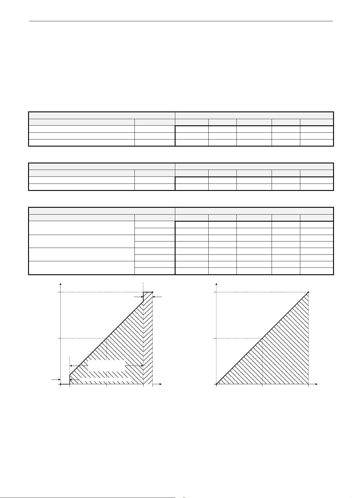
final position of shaft adapter (% of max. stroke)
100
50
0
upper dead band (9.76 to 10.0 V)
range of proportional
actuator movement
(0.24 to 9.76 V)
lower dead band (0 to 0.24 V)
00.24
control signal (V)
5.0 10.09.76
Fig. 4. Final shaft adapter position in dependence upon
control signal (example function selection switch setting
of 0...10 V)
100
50
0
0
current position of shaft adapter (% of max. stroke)
feedback signal (V)
510
Fig. 5. Feedback signal in dependence upon current
position of shaft adapter (example function selection
switch setting of 0...10 V)
3 EN0B-0478GE51 R0408
Page 4

N05010/N10010 DAMPER ACTUATORS FOR MODULATING AND FLOATING/2-POSITION CONTROL
Adaption
Adaption is a function in which the actuator re-maps its feedback signal and control signal in accordance with repositioned
mechanical end limits (see also Fig. 6) and thus recognizes
their new positions.
100
(before)
100
(after)
final position of
0
(after)
0
(before)
a
r
e
t
f
a
actuator (% of max.)
e
or
f
be
010.0
new position of UPPER
mechanical end limit
n
o
i
t
p
a
d
on
i
pt
new position of LOWER
da
a
mechanical end limit
control signal (volts)
95
final position of actuator (degrees)
0
Fig. 6. Adaption (function selection switch set to
"0...10 V")
Adaption will be carried out whenever the actuator is in the
modulating mode or the floating plus feedback mode or the 2position plus feedback mode and
• the user powers up (from a totally powerless condition) the
actuator; or
• the user sets the function selection switch to the
"Service/Off" setting for at least 2 sec and then back to its
previous setting; or
• the control signal's value rises up into the upper dead
band (i.e. to more than the max. control signal minus
0.24 V) or drops down into the lower dead band (i.e. to
less than the min. control signal plus 0.24 V), after which
the shaft adapter must then remain at the respective
(upper or lower) mechanical end limit for at least 3 sec.
However, in this case, the actuator will then recognize the
position of only the respective (upper or lower) mechanical
end limit.
Accuracy
To achieve very exact positioning or synchronicity from
several actuators running in parallel, ensure that the actuator
does one synchronization run per day (i.e. drive the actuator
into the upper dead band, hold for min. 3 sec, then drive the
actuator into the lower dead band, and then hold for min. 3
sec.) See section "Adaption" for exact voltage levels.
Overriding
An override is a condition in which a 24 V signal is applied to
terminal 4 of an actuator in the modulating mode, thus
causing the actuator to ignore the control signal at terminal 3,
whereupon it will instead move to a position of 50% of its
max. stroke (see Table 3).
Feedback
If correspondingly wired (see Fig. 11, Fig. 12, and Fig. 13),
the actuator provides, via terminal 5, a feedback signal proportional to the actual position of the shaft adapter.
MANUAL ADJUSTMENT
IMPORTANT
To prevent equipment damage, you must remove
power or set the function selection switch to the
"Service/Off" position before manual adjustment.
After removing power or setting the function selection switch
to the "Service/Off" position, the gear train can be disengaged
using the declutch button, permitting the shaft adapter to be
manually rotated to any position. If you have wired the
actuator for feedback signal, then, after adaption, the
feedback signal will follow the new position.
Limitation of Rotation Stroke
Two adjustable mechanical end limits are provided to limit the
angle of rotation as desired (see Fig. 7). The mechanical end
limits must be securely fastened in place.
Fig. 7. Mechanical end limits
To ensure tight closing of the dampers, the shaft adapter has
a total rotation stroke of 95°.
After adjusting the mechanical end limits, the user should
trigger adaption (see section "Adaption").
INTERNAL END SWITCHES
NOTE: Only those actuators for which "-SW2" has been
specified when ordering (e.g.: "N05010-SW2")
feature internal end switches.
The internal end switches "A" and "B" are changeover
switches which are activated when the shaft adapter moves
past a position of 5° and 85°, respectively (see also Table 5).
changeover switch A activated
when shaft adapter moves past 5°
-2.5° 92.5°5° 10° 15°0° 90°85°80°75°
Fig. 8. Internal end switch triggering points
changeover switch B activated
when shaft adapter moves past 85°
EN0B-0478GE51 R0408 4
Page 5

N05010/N10010 DAMPER ACTUATORS FOR MODULATING AND FLOATING/2-POSITION CONTROL
INSTALLATION
CAUTION
To avoid personal injury (electrical shock) and to
prevent equipment damage, before installation,
you must remove power.
These actuators are designed for single-point mounting.
Mounting Instructions
All information and steps are included in the Installation
Instructions (Product Literature No.: MU1B-0276GE51)
supplied with each actuator.
Mounting Position
The actuators can be mounted in any position (IP54 is
dependent upon orientation; see Fig. 9). Choose a mounting
position permitting easy access to cables and controls.
IP54 IP54IP54 IP54
WIRING
CAUTION
To avoid personal injury (electrical shock) and to
prevent equipment damage, before wiring, you
must remove power.
Connecting to the Power Supply
In order to comply with protection class II, the power source of
24 V actuators must be reliably separated from the network
power supply circuits as per DIN VDE 0106, part 101.
Access Cover
IMPORTANT
Once the access cover has been removed, please
take care to avoid damaging any of the parts now
accessible.
The access cover can be unscrewed and removed in order to
gain access to the terminal block(s) and perform wiring.
Fig. 9. Mounting for IP54
NOTE: Further, in order to guarantee IP54, only original
Honeywell grommets may be used.
Anti-Rotation Bracket and Screws
If the actuator is to be mounted directly on a damper shaft,
use the anti-rotation bracket and screws included in the
delivery package. The min. distance between the center of
the damper shaft and the middle of the anti-rotation bracket is
85 mm; a max. of 108 mm is allowed (see also Fig. 15).
Depending upon the specifics of your mounting site, the
actuator may shift in position slightly while tightening the
screws at the top of the shaft adapter. The anti-rotation
bracket features a T-piece with a 5-mm-long shank to
accommodate for this movement. It is important to ensure
that this play is not impeded.
Universal Shaft Adapter
The universal shaft adapter can be used for shafts of various
diameters and shapes (round: 8...16 mm and square:
6...13 mm).
1
5
4
3
5
2
4
1
3
2
1
1
S
2
S
3
S
5
S
6
S
1
S
2
S
3
S
5
S
6
S
2
removable access cover
Fig. 10. Access cover
5 EN0B-0478GE51 R0408
Page 6

N05010/N10010 DAMPER ACTUATORS FOR MODULATING AND FLOATING/2-POSITION CONTROL
A
Wiring Diagrams
Modulating: 0[2]...10V, 10...0[2]V
24V~/=
END SWITCHES
(max. 230 V, 5 A)
24V~/+
1
GND/-
2
0[2]...10V
0[2]...10V
!
Fig. 11. N05010/N10010 (modulating mode)
Floating: Dir
24V~/=
0[2]...10V
!
Fig. 12. N05010/N10010 (floating mode)
= feedback option
Y in
3
POS 50%
4
POS out
5
= override option
24V~/+
1
GND/-
2
CW
3
CCW
4
POS out
5
NOTE: Both of the internal end switches must be connected
Table 4 and Table 5 summarize the information presented in
the preceding wiring diagrams.
minal
1
2
3
4
5
2-Position: Dir
NOTE: All cables connected to these terminals must be
24V~/=
24V~/+
1
GND/-
2
CW
3
CCW
4
0[2]...10V
!
Fig. 13. N05010/N10010 (2-position mode)
= feedback option
5
POS out
terminal type of switch
S2, S3
S5, S6
A,B: C
A: NC
A: NO
B: NC
B: NO
Fig. 14. End switches (Nxx-SW2)
to the same power source.
Table 4. Signals at terminals
modulating floating 2-position
24 V ~/+
(power)
common ~/- common ~/- common ~/-
0[2]...10 V
(control)
24 V ~/+
(override)
0[2]...10 V
(feedback)
equipped with spark suppression.
Table 5. Internal end switches (Nxx-SW2)
S1
common lead for switches A and B
change-over switch A (S1/S2 opens and S1/S3
closes when shaft adapter moves CW past 5°;
reverts to original state when shaft adapter
moves CCW past 5°).
change-over switch B (S1/S5 opens and S1/S6
closes when shaft adapter moves CW past 85°;
reverts to original state when shaft adapter
moves CCW past 85°).
S1
S2
S3
S5
S6
mode ter-
unused or
(with feedback)
24 V ~/+ (power)
24 V ~/+
(control signal)
24 V ~/+
(control signal)
unused or
(with feedback)
0...10 V
(with feedback)
24 V ~/+ (power)
(control signal)
(control signal)
(with feedback)
B
unused or
24 V ~/+
24 V ~/+
unused or
0...10 V
EN0B-0478GE51 R0408
6
Page 7

N05010/N10010 DAMPER ACTUATORS FOR MODULATING AND FLOATING/2-POSITION CONTROL
SPARE PARTS
Anti-Rotation Bracket Kit
Order no.: A7211.2073
Contains:
• 10 anti-rotation brackets
• 20 screws
Spare Parts Kit
Order no.: A7211.2071
Contains:
• 1 anti-rotation bracket + screws
• 2 universal terminal blocks
• 2 strain-relief clamps
• 2 grommets*
• 2 adjustable end stops
*In order to guarantee IP54, only original Honeywell
grommets may be used.
7 EN0B-0478GE51 R0408
Page 8
N05010/N10010 DAMPER ACTUATORS FOR MODULATING AND FLOATING/2-POSITION CONTROL
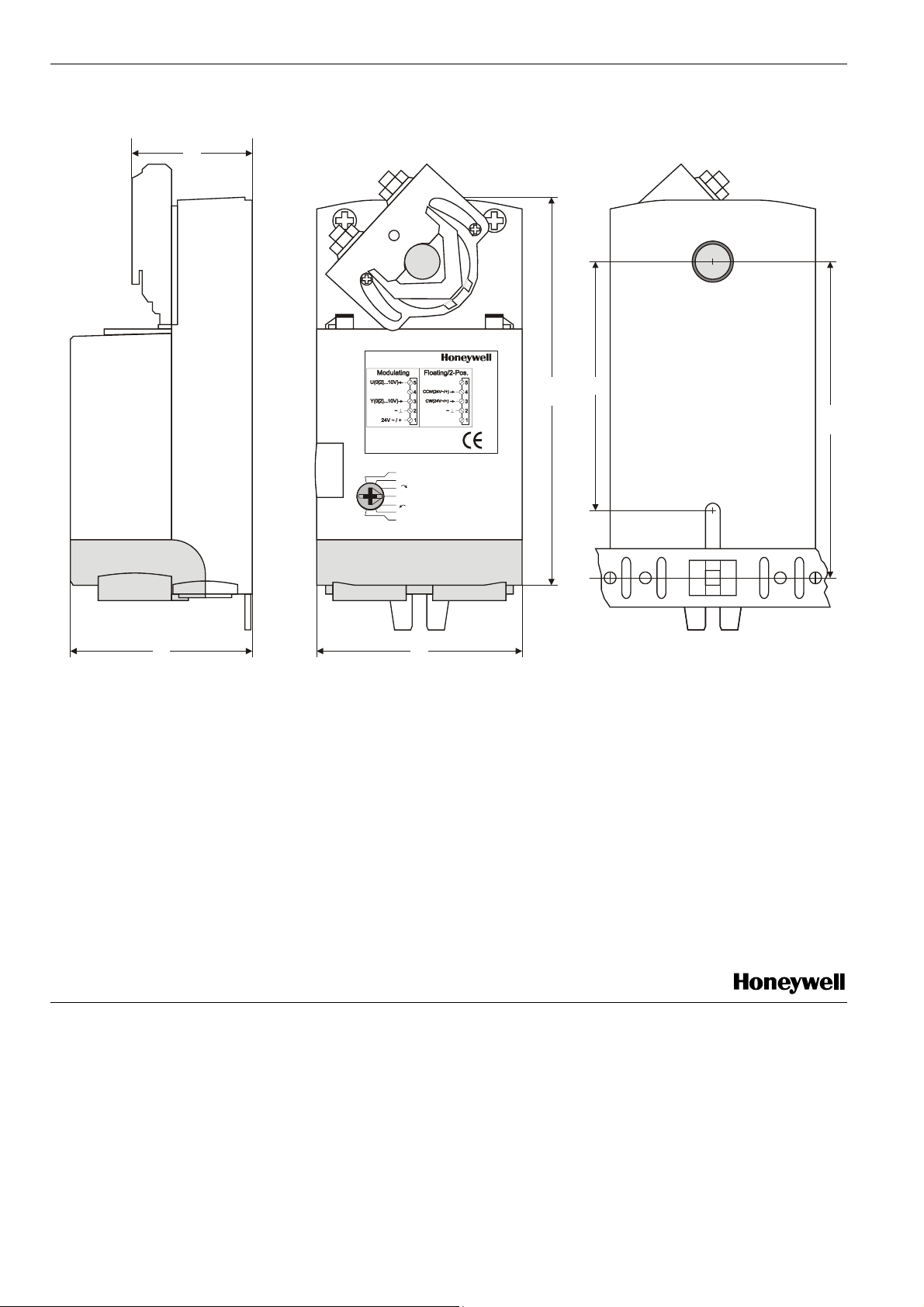
DIMENSIONS
41
N05010
85
134
2...10 V
0...10 V
Dir
Service/Off
Rev
10...0 V
10...2 V
108
6662
Fig. 15. Dimensions (in mm)
Manufactured for and on behalf of the Environmental and Combustion Controls Division of Honeywell Technologies Sàrl, Ecublens, Route du Bois 37, Switzerland by its Authorized Representative:
Automation and Control Solutions
Honeywell GmbH
Böblinger Strasse 17
71101 Schönaich
Germany
Phone: (49) 7031 63701
Fax: (49) 7031 637493
http://ecc.emea.honeywell.com
Subject to change without notice. Printed in Germany
EN0B-0478GE51 R0408
 Loading...