

Honeywell MX8000 Installation And Operation Manual

ADEMCO MX8000
ADEMCO MX8000––––3EX
ADEMCO MX8000ADEMCO MX8000
Digital Alarm Receiver
Digital Alarm Receiver
Digital Alarm ReceiverDigital Alarm Receiver
3EX
3EX3EX
Installation and Operation Guide
K5982-1 1/10 Rev. A

Table of Contents
Section 1 System Overview.....................................................................................................................................1–1
1.1 Features ................................................................................................................................................................1–1
1.2 Optional Accessories...........................................................................................................................................1–1
1.3 Formats Compatible with the MX8000–3EX ....................................................................................................1–2
1.4 MX8000–3EX Supported SIA Digital I-III Levels .............................................................................................1–3
1.5 How to Use this Manual ......................................................................................................................................1–3
1.6 Terminology ..........................................................................................................................................................1–4
1.7 What’s in the Box .................................................................................................................................................1–4
1.8 General Recommendations, Notes, and Limitations ......................................................................................1–5
1.9 How to Contact Technical Support.................................................................................................................... 1–7
Section 2 Agency Requirements............................................................................................................................2–1
2.1 Telephone Requirements....................................................................................................................................2–1
2.1.1 General Information .............................................................................................................................................2–1
2.1.2 CE Telco Approval, TBR 21: October 1998 .....................................................................................................2–1
2.2 FCC Statement.....................................................................................................................................................2–1
2.3 Industry Canada Statements.............................................................................................................................. 2–1
2.4 UL Requirements .................................................................................................................................................2–2
Section 3 Installation.................................................................................................................................................3–1
3.1 Quick Start ............................................................................................................................................................3–1
3.2 Environmental specifications .............................................................................................................................. 3–1
3.3 Electrical Specifications ......................................................................................................................................3–1
3.4 Overview................................................................................................................................................................3–2
3.5 Rack Mounting......................................................................................................................................................3–3
3.6 Hot Swapping of Line Cards............................................................................................................................... 3–4
3.7 Line Card Installation ........................................................................................................................................... 3–5
3.8 Removing Line Cards ..........................................................................................................................................3–6
3.9 Telephone Line Connection................................................................................................................................3–7
3.10 Parallel Printer Connection.................................................................................................................................3–7
3.10.1 Printer Cable Pin-Outs ........................................................................................................................................3–8
3.10.2 Com Ports 1 and 2 ............................................................................................................................................... 3–8
3.10.3 Remote Alert Output............................................................................................................................................3–9
3.11 AC Power Cord Connection ...............................................................................................................................3–9
3.12 Battery Connection ..............................................................................................................................................3–9
3.13 Automation Computer Connection ..................................................................................................................3–10
3.13.1 Computer Port Baud Rate Selection...............................................................................................................3–11
3.14 Master/Slave Receiver Linking.........................................................................................................................3–11
3.14.1 Receiver Linking Cabling Connections ........................................................................................................... 3–11
3.14.2 Master/Slave Linking Programming ................................................................................................................3–11
Section 4 Operation...................................................................................................................................................4–1
4.1 Touchpad Function Buttons................................................................................................................................4–1
4.2 Displays .................................................................................................................................................................4–2
4.2.1 LED Displays ........................................................................................................................................................4–2
4.2.2 VFD Status Display..............................................................................................................................................4–3
4.3 Initial System Power Up ...................................................................................................................................... 4–4
4.4 Log On / Log Off...................................................................................................................................................4–4
4.4.1 Installer Profile ...................................................................................................................................................... 4–4
4.4.2 Operator Profile ....................................................................................................................................................4–4
4.4.3 Default User Codes .............................................................................................................................................4–5
4.4.4 How to log on the system. ..................................................................................................................................4–5
4.4.5 How to log off the system. ..................................................................................................................................4–5
4.5 Modes of Operation .............................................................................................................................................4–6
4.5.1 Normal Mode ........................................................................................................................................................4–6
4.5.2 Program Mode ...................................................................................................................................................... 4–6
4.6 Main Menu ............................................................................................................................................................4–6
4.6.1 How to Display the Main Menu ..........................................................................................................................4–7
4.6.2 How to Maneuver Through Main Menu ............................................................................................................4–7
ii

Call History............................................................................................................................................................4–8
4.6.3
4.6.4 System History .....................................................................................................................................................4–9
4.6.5 System Info ...........................................................................................................................................................4–9
4.6.6 Set Time & Date ...................................................................................................................................................4–9
4.6.7 System Restart................................................................................................................................................... 4–10
4.6.8 Printer Menu .......................................................................................................................................................4–11
4.6.9 Program Menu .................................................................................................................................................... 4–16
4.6.10 Diagnostics Menu...............................................................................................................................................4–16
4.7 Listen-In and Hang Up ......................................................................................................................................4–19
4.7.1 Extend Manual (Common) Listen-In Operation.............................................................................................4–19
4.7.2 PBX Operation....................................................................................................................................................4–20
4.8 Testing the System ............................................................................................................................................4–20
Section 5 Programming............................................................................................................................................5–1
5.1 How to Enter Program Mode..............................................................................................................................5–1
5.1.1 Programming Fields.............................................................................................................................................5–1
5.1.2 How to Maneuver Around in Program Mode....................................................................................................5–1
5.2 Programming Choices .........................................................................................................................................5–2
5.3 General Options ...................................................................................................................................................5–2
5.3.1 Operation Mode....................................................................................................................................................5–6
5.3.2 Display Options ....................................................................................................................................................5–7
5.3.3 Communications................................................................................................................................................. 5–12
5.3.4 System Options ..................................................................................................................................................5–22
5.3.5 Message Queue Options ..................................................................................................................................5–25
5.3.6 Slave List.............................................................................................................................................................5–26
5.3.7 Virtual Receiver/Line Numbers ........................................................................................................................5–27
5.4 Line Device Menu ..............................................................................................................................................5–28
5.4.1 Add Line Device .................................................................................................................................................5–33
5.4.2 Edit Line – MX8000–LC3 (3 Line) ...................................................................................................................5–34
5.4.3 Copy Device(s) ................................................................................................................................................... 5–49
5.4.4 Clear Device .......................................................................................................................................................5–50
5.4.5 View Devices ...................................................................................................................................................... 5–50
5.5 User List ..............................................................................................................................................................5–51
5.5.1 Adding a User.....................................................................................................................................................5–51
5.5.2 Editing a User .....................................................................................................................................................5–52
5.5.3 Clearing a User Out of the Receiver ...............................................................................................................5–53
Section 6 Compatible Reporting Formats ...........................................................................................................6–1
6.1 Formats By Communication Group. .................................................................................................................. 6–1
6.2 Format Numbers Used In Printer Output..........................................................................................................6–3
Section 7 Troubleshooting ......................................................................................................................................7–1
7.1 Error Messages....................................................................................................................................................7–1
7.2 Unrecognized Reports.........................................................................................................................................7–4
7.3 Troubleshooting Process ....................................................................................................................................7–4
7.3.1 Removing the CPU, PS, User Interface Assembly .........................................................................................7–5
7.3.2 Replacing the CPU, PS, User Interface Assembly .........................................................................................7–5
7.4 Safe Mode ............................................................................................................................................................. 7–5
Section 8 Automation Communication Formats................................................................................................8–1
8.1 Introduction ...........................................................................................................................................................8–1
8.1.1 Conventions Observed In This Section ............................................................................................................8–1
8.2 MX8000–3EX Automation Protocols.................................................................................................................8–1
8.3 Reporting Formats and Automation Protocol Support.................................................................................... 8–2
8.4 ADEMCO 8000.....................................................................................................................................................8–3
8.4.1 AE Header Block .................................................................................................................................................. 8–3
8.4.2 Call Message Block .............................................................................................................................................8–3
8.4.3 System Message Block.......................................................................................................................................8–7
8.4.4 Heart Beat Message Block .................................................................................................................................8–8
8.4.5 Validation Byte (V-Byte) ......................................................................................................................................8–9
8.4.6 ACKing and NACKing Data................................................................................................................................8–9
8.4.7 Commands Initiated by the Automation Computer .........................................................................................8–9
8.5 ADEMCO 685 Automation Protocol ................................................................................................................ 8–13
iii

Low Speed 3x1, 4x1, and 4x1 Express Automation Protocols.................................................................... 8–13
8.5.1
8.5.2 Low Speed 4x2 and 4x2 Express Automation Protocols .............................................................................8–13
8.5.3 ADEMCO High Speed Automation Protocols ................................................................................................8–13
8.5.4 685 Contact ID....................................................................................................................................................8–14
8.5.5 MX8000–3EX/685 System Messages ............................................................................................................8–20
8.6 CAPS Automation Protocol ..............................................................................................................................8–20
8.7 FBII CP-220 Automation Protocol ...................................................................................................................8–22
8.7.1 3x1, 4x1, and 4x2 Automation Protocols ........................................................................................................8–22
8.7.2 Acron 11 Digit with Zero or Space...................................................................................................................8–22
8.7.3 FBII Superfast.....................................................................................................................................................8–22
8.7.4 CP-220 Contact ID.............................................................................................................................................8–22
8.7.5 CP-220/Silent Knight .........................................................................................................................................8–23
8.7.6 MX8000–3EX/CP-220 System Messages......................................................................................................8–24
8.8 SK9000 Protocol ................................................................................................................................................8–25
8.8.1 Data String Description And Special Characters ..........................................................................................8–25
8.8.2 Calls From Panels..............................................................................................................................................8–26
8.8.3 Long Calls ...........................................................................................................................................................8–26
8.8.4 Bad Data..............................................................................................................................................................8–27
8.8.5 Good Data with Bad Data ................................................................................................................................. 8–27
8.8.6 Validation Byte (V-Byte) ....................................................................................................................................8–27
8.8.7 System Messages..............................................................................................................................................8–28
8.8.8 Communication from a Computer to the MX8000–3EX ............................................................................... 8–28
8.9 ITI Generic Computer Format ..........................................................................................................................8–29
8.9.1 Convention Used In This Section ....................................................................................................................8–29
8.9.2 Report Record ....................................................................................................................................................8–29
8.9.3 Log Record.......................................................................................................................................................... 8–31
8.9.4 Test Record ........................................................................................................................................................8–32
8.9.5 OKAY Record ..................................................................................................................................................... 8–32
8.9.6 ACKing and NACKing Data..............................................................................................................................8–32
8.10 ITI Computer Interface Format......................................................................................................................... 8–32
8.10.1 Convention Used In This Section ....................................................................................................................8–32
8.10.2 General Record Structure ................................................................................................................................. 8–33
8.10.3 Report Record ....................................................................................................................................................8–33
8.10.4 Test Record ........................................................................................................................................................8–36
8.10.5 Supervisory Record ...........................................................................................................................................8–37
8.10.6 Log Records........................................................................................................................................................8–37
8.10.7 Checksum/Control Field....................................................................................................................................8–37
8.11 US ASCII Character Code ................................................................................................................................8–38
Appendix A Programming Quick Chart ................................................................................................................... A–1
Appendix B Receiver Update Procedure................................................................................................................. B–1
Appendix C Index .......................................................................................................................................................... C–1
iv

List of Tables
Table 1–1: Optional Accessories for the MX8000–3EX Receiver .................................................................................1–2
Table 1–2: Formats Compatible with the MX8000–3EX .................................................................................................1–2
Table 1–3: MX8000–3EX and SIA Levels I-III comparison.............................................................................................1–3
Table 3–1: External Printer Cable Pin Description...........................................................................................................3–8
Table 4–1: Touchpad Buttons Description ........................................................................................................................4–2
Table 4–2: LED Description.................................................................................................................................................4–3
Table 4–3: VFD and Printer Abbreviations ........................................................................................................................4–4
Table 4–4: Main Menu Option Items by Profile.................................................................................................................4–5
Table 4–5: Default User Codes...........................................................................................................................................4–5
Table 4–6: Printer Menu Choices .....................................................................................................................................4–11
Table 4–7: Event Format Choices and Meaning ............................................................................................................4–14
Table 4–8: Phantom Signals Formats List ......................................................................................................................4–16
Table 4–9: Abbreviation Display Character Meanings/High Low Status ....................................................................4–19
Table 5–1: Types of Programming Fields..........................................................................................................................5–1
Table 5–2: General Options Items and Description .........................................................................................................5–3
Table 5–3: Operation Mode Choices and Descriptions...................................................................................................5–6
Table 5–4: Display Options and Descriptions ...................................................................................................................5–7
Table 5–5: Communications Options and Description ..................................................................................................5–12
Table 5–6: Initialization String Characters.......................................................................................................................5–17
Table 5–7: ITI Automation Format Options .....................................................................................................................5–20
Table 5–8: On-board Annunciator and Auxiliary Relay Options ..................................................................................5–21
Table 5–9: System Options ...............................................................................................................................................5–22
Table 5–10: 685, CAPS, and CP-220 1–9/A–Z Entries.................................................................................................5–23
Table 5–11: Line Device Menu Options...........................................................................................................................5–29
Table 5–12: MX8000–LC3 Edit Line List Items and Description..................................................................................5–34
Table 5–13: Valid Programmable String Characters .....................................................................................................5–40
Table 5–14: Account Characters ......................................................................................................................................5–41
Table 5–15: User List Menu Items and Steps.................................................................................................................5–51
Table 5–16: Available Characters.....................................................................................................................................5–52
Table 6–1: Formats compatible with the MX8000–3EX ..................................................................................................6–1
Table 6–2: Formats By Report Number .............................................................................................................................6–3
Table 7–1: Error Messages .................................................................................................................................................7–1
Table 8–1: Automation Protocol Listing .............................................................................................................................8–1
Table 8–2: Reporting Formats and Automation Protocol Support .................................................................................8–2
Table 8–3: AE Header Block Components Description...................................................................................................8–3
Table 8–4: Call Message Components and Description .................................................................................................8–3
Table 8–5: Dialer Format Types By Code .........................................................................................................................8–4
Table 8–6: Panel Data Identifiers and Descriptions.........................................................................................................8–4
Table 8–7: Call Message Components..............................................................................................................................8–5
Table 8–8: Call Message With Listen-in Data...................................................................................................................8–6
Table 8–9: Bad Data Field Indicator Components ...........................................................................................................8–7
Table 8–10: System Message Components .....................................................................................................................8–7
Table 8–11: System Messages...........................................................................................................................................8–8
Table 8–12: Link Test Components ...................................................................................................................................8–9
Table 8–13: Response Messages by the MX8000–3EX Receiver ..............................................................................8–10
Table 8–14: Command Requests by Identifiers .............................................................................................................8–10
Table 8–15: Log-in Request Components.......................................................................................................................8–10
Table 8–16: Log-off Request Components .....................................................................................................................8–11
Table 8–17: Force Hang-Up Request Components.......................................................................................................8–11
Table 8–18: Add Listen-in Account Request Components ...........................................................................................8–11
Table 8–19: Delete a Listen-in Account Request Components ...................................................................................8–11
Table 8–20: Extend Listen-in Period Request Components.........................................................................................8–12
Table 8–21: End Listen-in Period Request Components ..............................................................................................8–12
Table 8–22: Delete a Listen-in Account Request Components ...................................................................................8–12
Table 8–23: Contact ID Event Definition Codes .............................................................................................................8–15
Table 8–24: MX8000–3EX/685 System Messages .......................................................................................................8–21
v

Table 8–25: MX8000–3EX/CP-220 System Messages
.................................................................................................8–24
Table 8–26: Data String Description ................................................................................................................................8–25
Table 8–27: Special Characters Used in the Protocol...................................................................................................8–25
Table 8–28: System Messages.........................................................................................................................................8–28
Table 8–29: Number and ITI Digit Equivalent .................................................................................................................8–29
Table 8–30: Report Record Components........................................................................................................................8–29
Table 8–31: Upper Nibble Description .............................................................................................................................8–30
Table 8–32: Lower Nibble Description .............................................................................................................................8–30
Table 8–33: Extended Panel ID Codes (XID) .................................................................................................................8–30
Table 8–34: Alarm Code and Description........................................................................................................................8–31
Table 8–35: Log Record Components and Description ................................................................................................8–31
Table 8–36: Test Record Components and Description ...............................................................................................8–32
Table 8–37: Okay Record Components and Description..............................................................................................8–32
Table 8–38: Number and ITI Digit Equivalent .................................................................................................................8–33
Table 8–39: Type of Record Identifiers............................................................................................................................8–33
Table 8–40: Record Components.....................................................................................................................................8–33
Table 8–41: Report Record Components and Description ...........................................................................................8–34
Table 8–42: Information Field Identifiers .........................................................................................................................8–34
Table 8–43: Panel Type Characters.................................................................................................................................8–35
Table 8–44: Condition Codes and Descriptions .............................................................................................................8–36
Table 8–45: Test Record Information Fields and Descriptions ....................................................................................8–36
Table 8–46: Log Record Information Fields and Descriptions .....................................................................................8–37
Table 8–47: Checksum Verification Process ..................................................................................................................8–38
Table 8–48: US ASCII Character Code ...........................................................................................................................8–38
Table A–1: Programming Quick Chart..................................................................................................................................... A–1
vi

List of Figures
Figure 3–1: MX8000–3EX Front View ..............................................................................................................................3–2
Figure 3–2: MX8000–3EX Front View Without Front Plate Attached...........................................................................3–2
Figure 3–3: MX8000–3EX Rear View ...............................................................................................................................3–2
Figure 3–4: Rack Mount Enclosure, Front View ..............................................................................................................3–3
Figure 3–5: Rack Mount Enclosure, Rear View...............................................................................................................3–4
Figure 3–6: Line Card Locations........................................................................................................................................3–5
Figure 3–7: Line Card Position and Components ...........................................................................................................3–6
Figure 3–8: Parallel Printer Cable Connection to MX8000–3EX ..................................................................................3–7
Figure 3–9: Wiring Sequence For Parallel Printer Port Interface..................................................................................3–8
Figure 3–10: MX8000–3EX Remote Alert Output/Backup Battery Connection..........................................................3–9
Figure 3–11: Battery Connections ...................................................................................................................................3–11
Figure 3–12: 25-Pin Null Modem Cable Connection ....................................................................................................3–11
Figure 3–13: 9-Pin Null Modem Cable Connection.......................................................................................................3–12
Figure 3–14: MX8000–3EX Master/Slave Receiver Linking Cabling Connections..................................................3–13
Figure 3–15: SBUS Receiver Linking Cable ..................................................................................................................3–13
Figure 4–1: MX8000–3EX Front Panel .............................................................................................................................4–1
Figure 4–2: Touchpad Layout ............................................................................................................................................4–1
Figure 4–3: VFD Display.....................................................................................................................................................4–3
Figure 4–4: Power-up Routine ...........................................................................................................................................4–4
Figure 4–5: Main Menu Display .........................................................................................................................................4–7
Figure 4–6: Main Menu Controls .......................................................................................................................................4–8
Figure 4–7: View of a Call History Screen........................................................................................................................4–8
Figure 4–8: System History Display Sequence ...............................................................................................................4–9
Figure 4–9: System Information Display...........................................................................................................................4–9
Figure 4–10: Setting Time and Date Program Sequence ............................................................................................4–10
Figure 4–11: System Restart Display .............................................................................................................................4–10
Figure 4–12: Print Menu Items.........................................................................................................................................4–11
Figure 4–13: Print Report Menu Items............................................................................................................................4–12
Figure 4–14: Call History Options....................................................................................................................................4–12
Figure 4–15: System Configuration Print Items.............................................................................................................4–13
Figure 4–16: Event Format Menu Items .........................................................................................................................4–14
Figure 4–17: Program Menu Items..................................................................................................................................4–16
Figure 4–18: Diagnostics Menu Items ............................................................................................................................4–16
Figure 4–19: Message Queue Level ...............................................................................................................................4–17
Figure 4–20: Event Log Display.......................................................................................................................................4–17
Figure 4–21: Diagnostic Formats.....................................................................................................................................4–17
Figure 4–22: Select LC Debug Mode by Line Card ......................................................................................................4–17
Figure 4–23: Line Statistics Display ................................................................................................................................4–18
Figure 4–24: Port Status View of Serial Port .................................................................................................................4–18
Figure 4–25: Parallel Port Status View ...........................................................................................................................4–18
Figure 4–26: Phone Connector Pin-Out and Listen-in Wiring Diagram .....................................................................4–20
Figure 5–1: Programming Controls ...................................................................................................................................5–2
Figure 5–2: Program Menu Choices .................................................................................................................................5–2
Figure 5–3: General Options Display ................................................................................................................................5–2
Figure 5–4: Normal Operating Mode Display Indicating Manual Operation................................................................5–6
Figure 5–5: View of Display Options .................................................................................................................................5–7
Figure 5–6: Communications Options Menu..................................................................................................................5–12
Figure 5–7: Initialization String Display...........................................................................................................................5–16
Figure 5–8: System Options Display ...............................................................................................................................5–22
Figure 5–9: Message Queue Display..............................................................................................................................5–25
Figure 5–10: Slave List Display .......................................................................................................................................5–26
Figure 5–11: Virtual Receiver/Line Numbers Display...................................................................................................5–27
Figure 5–12: Choosing Line Device Menu and Line Device Program Menu Items .................................................5–28
Figure 5–13: MX8000–LC3 Handshake Sequence Menu ...........................................................................................5–34
Figure 5–14: MX8000–LC3 Handshake Order Number...............................................................................................5–35
Figure 5–15: MX8000–LC3 Line Options Menu ............................................................................................................5–37
vii

Figure 5–16: MX8000–LC3 Listen Mode Menu Display
...............................................................................................5–39
Figure 5–17: MX8000–LC3 Listen In Accounts Menu..................................................................................................5–41
Figure 5–18: MX8000–LC3 Miscellaneous Phone Line Options ................................................................................5–42
Figure 5–19: MX8000–LC3 Ring Options ......................................................................................................................5–43
Figure 5–20: MX8000–LC3 ADEMCO Auto Output Options .......................................................................................5–45
Figure 5–21: MX8000–LC3 Line Gain Options..............................................................................................................5–47
Figure 5–22: Visual Steps to Clear a Line From the Receiver ....................................................................................5–50
Figure 5–23: User List Menu Items .................................................................................................................................5–51
Figure 7–1: User CPU, PS, User Interface Assembly retaining Screw Locations......................................................7–5
Figure 8–1: 685 3x1, 4x1, 4x1 Express Protocol...........................................................................................................8–13
Figure 8–2: 685 4x2 and 4x2 Express Protocol.............................................................................................................8–13
Figure 8–3: 685 ADEMCO High Speed Protocol ..........................................................................................................8–14
Figure 8–4: 685 Contact ID Protocol...............................................................................................................................8–14
Figure 8–5: CAPS 4x2 and 4x2 Express Protocol ........................................................................................................8–20
Figure 8–6: CP-220 3x1, 4x1, 4x2 Protocol ...................................................................................................................8–22
Figure 8–7: CP-220 Acron 11 Digit Protocol ..................................................................................................................8–22
Figure 8–8: CP-220 FBII Superfast Protocol .................................................................................................................8–22
Figure 8–9: CP-220 Contact ID Protocol ........................................................................................................................8–23
Figure 8–10: CP-220/Silent Knight Format 0.................................................................................................................8–23
Figure 8–11: CP-220/Silent Knight Format 1 (FSK 1) ..................................................................................................8–23
Figure 8–12: CP-220/Silent Knight Format 6 (FSK 2) ..................................................................................................8–24
Figure 8–13: SK9000 Example Message.......................................................................................................................8–26
Figure 8–14: Long Event Data .........................................................................................................................................8–27
Figure 8–15: System Message ........................................................................................................................................8–28
viii

Important notes on MX8000-3EX
The MX8000-3EX Receiver is only intended to operate on 220-240VAC, 50/60 Hz
The clock synchronization may be needed to be set to match the power line frequency. It may be set to 50 Hz, 60 Hz, or
Internal. Internal may need to be used if the power line frequency in the installation site is not stable. Frequency instability
will cause drifting of the time and date.
See Section 5.3.4.1 and Table 5-9 for information on setting the synchronization method.
Depending on the country of installation, the phone line characteristics of the MX8000 may need to be adjusted. This may be
done by setting the Country Code, as shown in Section 5.4.2.3. The choices available are:
Brazil
Australia
CTR21
USA
South Korea
South Africa
Poland
Philippines
Bulgaria
ix

x

Section 1 System Overview
This manual describes installation, operation, and programming of the MX8000–3EX Digital Alarm
Receiver. The MX8000–3EX can be used as a desktop receiver, however it must be rack-mounted to restrict
access to TNV circuitry. This section will list features, optional accessories, compatible formats, and SIA
options supported. This section also contains conventions held throughout the manual, terminology relevant
to this product, and other information.
To ensure the best possible performance from this product, please check the Honeywell Online Support web
site (HTTP://WWW.HONEYWELL.COM/SECURITY) for the latest code upgrades before placing this
product into service.
1.1 Features
Hardware:
• Supports 220-240 VAC installations at 60 and 50Hz operation.
• External annunciation with auxiliary Form C dry contact relay. (Programmable)
• On-board programmable piezo alert sounder.
• 1 parallel port.
• 2 serial ports.
• 2 rear SBUS connectors.
• Modular configuration for easy replacement and repair.
• 4 line Vacuum Fluorescent Display (VFD) with 20 characters for each line.
• On-board touchpad for manual operation and programming.
• LEDs to indicate system operations.
• Rack mountable design.
• One line card will communicate with all supported formats.
• Supports up to 12 3-port line cards where the ports operate independent of each other.
• Line Device parameters are stored in the Master Central Processing Unit for faster removal and
replacement.
• Line Devices support Caller ID.
• Line Devices are individually programmable for format priority and ring parameters.
• Line Devices support direct connect phone lines monitoring.
Software:
• Programmable display options for time and date information.
• View or print the history information by priority or by call or by event.
• Two user profiles to control user access to the receiver.
• Supports up to 40 users.
• Listen-in accounts support wild card variables.
• Listen-in selectable for direct, hook flash, or PBX phone system.
• Programmable port configuration for automation, printer and backup support.
• 500 event history buffer.
1.2 Optional Accessories
Table 1–1 lists optional accessories for the MX8000–3EX receiver. These accessories are available from our
sales department unless otherwise indicated.
1–1
MX8000-3EX Installation and Operation Guide
Table 1–1: Optional Accessories for the MX8000–3EX Receiver
Item
Three Line card MX8000–LC3 The 3 line card monitors the phone lines, detects ring and processes the
CPU, PS, User
Interface
Backup battery Acquire from a local retailer
Printer cable Acquire from a local retailer
SBUS cable Acquire from a local retailer A standard 4-wire RJ-11 reverse cable such as a Digi-Key H2642-14-ND that
Rack-mounting
cabinet
Blank filler panels Acquire from a local retailer Used to fill up any unused cabinet spaces.
Parallel printer Acquire from a local retailer
ADEMCO Model Number
(if applicable)
MX8000
(See Section 3.12 for
installation.)
Acquire from a local retailer
–CPU-EX
Description/Comments
message from the communicating panel.
The CPU, Power Supply, User Interface Assembly contains the VFD, main
processing board, and receiver power supply.
An approved 12VDC 7AH battery such as a Powersonic PS-1270 that will
provide a minimum 4 hours of backup power during an AC power loss.
A standard 25-pin cable used to connect the MX8000
external parallel printer.
is used to connect the receivers together for receiver linking.
Used to rack mount the MX8000
The ADEMCO MX8000
parallel printer such as the Okidata Microline 320 to generate a hardcopy of
report history.
–3EX receiver requires a UL approved dot matrix
–3EX receiver.
–3EX receiver to an
1.3 Formats Compatible with the MX8000–3EX
The MX8000–3EX receiver is compatible with all ADEMCO communicators.
Table 1–2 shows the formats that the MX8000–3EX receiver can decode and the handshake frequency
groups that accommodate that format (see Section 5.4 for line device programming). Each line device can
decode every format listed below. Setting the handshake order only prioritizes the type of communication
done by each line device. Section 6 of this manual describes the formats in greater detail.
Important Note: When selecting a reporting format and using an automation computer, it is essential that
you check Table 8–2: Reporting Formats and Automation Protocol Support to verify that the reporting format
selected is supported by the automation protocol that will be used.
Table 1–2: Formats Compatible with the MX8000–3EX
REPORTING FORMAT PPS or CPS
3/1, 3/1 Ext 10, 20, or 40 PPS ITI UltraGard N/A
3/1 Even Round 10, 20, or 40 PPS Radionics Modem II N/A
3/1 w/cksum 10, 20, or 40 PPS Radionics Modem IIE N/A
3/1 Ext w/cksum 10, 20, or 40 PPS SIA DCS N/A
3/2 10, 20, or 40 PPS SX-III, SX-IVA N/A
3/2 Even Round 10, 20, or 40 PPS SX-IVB N/A
3/2 w/cksum 10, 20, or 40 PPS Varitech FSK 4/1 N/A
4/1, 4/1 Ext 10 PPS
4/1 Even Round 10 PPS
4/1 w/cksum 10 PPS
4/1 Ext w/cksum 10 PPS
1400/2300 Hz Pulse
4/2 10 PPS
4/2 Even Round 10 PPS ADEMCO 4/1 w/cksum 10 PPS
4/2 w/cksum 10 PPS ADEMCO 4/2 w/cksum 10 PPS
BFSK N/A ADEMCO High Speed 10 CPS
FSK0/FSK 80 N/A ADEMCO High Speed w/cksum 10 CPS
FSK1/FSK 81 N/A Contact ID® 10 CPS
FSK2/FSK 86 N/A Contact ID®10 10 CPS
ITI CareTaker+, SecurityPro 4000 N/A FBII 4/3/1 10, 20, or 40 PPS
FSK
ITI Commander N/A
ITI Commander 2000, LifeGard N/A
ITI RF Commander, Harbor Gard N/A Westec 970 10 CPS
ITI SX-V N/A
REPORTING FORMAT PPS or CPS
FSK (cont’d)
Varitech FSK 4/2 N/A
Acron Touchtone w/ 3-digit
account
Acron Touchtone w/ 4-digit
account
DTMF
FBII 4/3/1 w/cksum
FBII Superfast
Westec 1000/2000/3000 10 CPS
10 CPS
10 CPS
10, 20, or 40 PPS
1–2
Section 1 – System Overview
1.4 MX8000–3EX Supported SIA Digital I-III Levels
Table 1–3 compares the MX8000–3EX receiver to SIA Digital Compatibility Levels I, II, and III and
indicates which of them we comply with.
Table 1–3: MX8000–3EX and SIA Levels I-III comparison
8000 Function/Capability Transmitter Receiver
✔
Support Tonal Acknowledgments required required
✔
Support N blocks with Zone Numbers Only required required
✔
Support single Account Block per Call required required
✔
Level I
Level II
Level III
Support O Blocks (optional) required
✔
Support X Blocks (optional) required
✔
Support 300 Baud (Fast) (optional) required
Support Configuration Block required required
Support Data Acknowledgments required required
✔
Support Modifier codes
✔
Support Multiple Account Blocks per Call (optional) required
✔
Support E Blocks (optional) required
✔
Support Data Codes with Units Numbers (optional) required
Support RECEIVER call out and Access Passcode required required
Support Reverse Channel C Blocks required required
Support Reverse Channel P Blocks required (optional)
Support Reverse Channel A Blocks (optional) required
Support Dynamic block and Group Sizes (optional) required
✔
Support Listen-in (optional) required
✔
Support A Blocks to RECEIVER (optional) required
Support V-Channel communication (optional) (optional)
id, da
and ti.
(optional) required
1.5 How to Use this Manual
This manual contains information on how to install, operate and program the MX8000–3EX receiver. We
strongly suggest that the manual be reviewed in its entirety to become familiar with procedures and
parameters of the product. Once you are familiar with the product, the manual can be used as a reference
document.
This manual uses the following conventions:
• A small graphic of each touchpad button is used to represent which touchpad key is to be pressed for a
given operation. For example, an up-arrow would be shown as:
• VFD display This represents messages that appear on the VFD (display).
• 2225Hz This typeface represents an editable field that appears on the VFD (display).
• Pages of the manual are numbered by section. For example, a page numbered as “5-1” is Page 1 of Section
5.
• When this manual refers to default settings, it means programmable options set at the factory. Any
programming after the receiver is powered up will change these setting.
1–3
MX8000-3EX Installation and Operation Guide
1.6 Terminology
This section lists terminology that is specific to this product and their meaning.
Term Meaning
ACK Stands for acknowledgment.
Automation Protocol The format used for messages sent between the receiver and the automation
computer.
Communication Group The different types of communication are separated by handshake type. These
handshake types can be assigned in a numbered order. (See Section 5 for more
details.)
Heartbeat A supervisory signal that continually tests the communication link between the
automation computer and the receiver.
Listen-in Listen-in is the ability to listen in to what is happening real-time from the central
station to a remote location. This can help the central station operator determine if he
or she should dispatch for a particular alarm situation.
Main Menu
MCPU Master Central Processing Unit.
NACK Stands for no acknowledgment.
PIN An abbreviation for Personal Identification Number. PINs are used to log in and out
PZT PZT is an abbreviation for a piezo alert sounder.
SBUS Serial Bus interface to connect a MX8000–3EX receiver to line cards, the VFD
VFD Stands for Vacuum Fluorescent Display. This is the type of message display used on
The main menu will be displayed as either <Installer Menu> or <Operator Menu>.
However, this manual will refer to them as the main menu.
of the receiver.
display and additional MX8000–3EX receivers via rear panel connectors.
the receiver.
1.7 What’s in the Box
This section contains a list of the parts that are shipped with the MX8000–3EX receiver and a brief
description of their intended use.
Item Quantity Description
Battery/Alert Relay Wiring
Harness
MX8000–3EX Installation
and Operation Guide
Digital Alarm Receiver 1 The digital alarm receiver assembly.
Line Card (See Note) 1 Line card for land lines.
Strain Relief Tie Wrap 1 Tie wrap used as a strain relief on the phone cord. See Figure 3–3
Receiver Mounting Screws 4 #10-32 x 1/2 flat head screws used to mount the receiver to a rack.
Power Cable 1 AC power cable used to connect the MX8000–3EX receiver to an AC
1 Wiring harness used to connect the MX8000–3EX receiver to a
backup battery. It also provides a normally open or normally closed
output for an alert sounder.
1 A manual covering installation and operation information related to
the MX8000–3EX receiver.
for location of strain relief tabs.
(See Section 3.5 for rack mounting instructions.)
wall plug.
1–4

Section 1 – System Overview
1.8 General Recommendations, Notes, and Limitations
The following listing contains items that it is helpful to be aware of:
• We recommend using the ADEMCO 8000 automation protocol so that you have access to the full system
capabilities.
• Do not mix formats containing the same number of reporting characters on the same line. For example,
do not have panels using 3+2 and 4+1 or 4+2 and 4+1 w/checksum reporting on the same line. If the
formats are mixed, the MX8000–3EX will not correctly determine the reporting formats being used and
incorrect messages will result.
• The receiver must be reset before the automation output will be correct any time the automation protocol
is changed or defined.
• When replacing a 685 or CP-220 with an MX8000–3EX, make certain that the ADEMCO Auto Options
for each line match what was set in the 685 or CP-220. The following chart is provided as an aid in
setting these options when converting from a 685.
685 Option Location
1 Inhibit translation of 4-
2 codes B and C to
High Speed ADEMCO
2 Restore Report
Translation to High
Speed (code 9)
3 Don't combine 3-1, 4-
1 expanded
messages
4 Disable BFSK into
High Speed
Messages (4-2
instead)
5 Use 4-2 for output of
low speed expanded
messages (3-1, 4-1)
PROM
Chart 7,
Slot 8
PROM
Chart 8
PROM
Chart 10,
Slot 2
PROM
Chart 10,
Slot 3
PROM
Chart 10,
Slot 6
Default
Setting
Convert to
High
Speed
Not
translated
Combined Pls – (Extended or
High
Speed
Not 4-2 ExtOut (High Speed
MX8000–3EX
Equivalent Option
42Out (Normal or
High Speed)
3/1 Rstr - (3/1 or
High Speed)
Not Extended)
BFSK - (4-2 or High
Speed)
or 4/2)
Default
Setting Rules / Examples
High
Speed
3/1 Standard method: 123 2, 123 9
Extended A sequence of 1234 B , BBBB 7
High
Speed
High
Speed
In High Speed mode, messages
with event codes of B and C are
translated to High Speed
Opening and Closing
messages, respectively. For
example, the message 1234 B
7 would be translated to:
1234 7222 2222 2.
Converted to High Speed:
0123 5355 5555 7
is combined into a 4-2 message
of 1234 B7. (Applies to
B,C,E,F). This message would
either be put out to Automation
as 4-2 or High Speed (see #5
below). When the option is
selected, the receiver does not
combine the expanded
messages. They are output in
the same form as received.
Same as #1 above except that
it applies to event codes B, C,
E, F.
If low speed expanded
messages are received and
combined (See # 3 above), the
messages are output to
Automation as 4-2 or High
Speed messages. For example,
a sequence of 1234 B , BBBB 7
is combined and output as a 4-2
message of 1234 B7.
1–5

MX8000-3EX Installation and Operation Guide
• When using the 685, CAPS, or CP-220 automation protocol, a limit applies to the number of line cards
that should be used for proper processing by most automation systems.
– The following examples apply when NOT using Virtual Receiver/Line numbers while using 685,
CAPS, or CP-220 automation protocols and are currently supported by most automation systems.
685 OR CAPS MODES - The example below allows up to 3 MX8000-LC3 cards giving 8 usable lines:
For MX8000-LC3
Line Number 1 4 7 10 13 16 19 22 25 28 31 34
MX8000-LC3 (Y = used) Y Y Y N N N N N N N N N
Device Slot
Alarms Report as Lines: 1,2,3 4,5,6 7,8
Line Faults as Line: 1,2,3 4,5,6 7,8
Notes: •••• Cards in slot 4 or higher may not be supported by your automation system when using 685, CAPS, or
CP-220 automation protocol.
• Cards in slot 4 or higher cannot report alarms or line troubles correctly when ADEMCO 685 or CAPS
automation protocol is chosen.
• Line 9 in slot 3 may not be used when using 685, CAPS, or CP-220.
1 2 3 4 5 6 7 8 9 10 11 12
CP-220 MODE - The example below allows up to 5 MX8000-LC3 cards giving 15 usable lines:
For MX8000-LC3
Line Number 1 4 7 10 13 16 19 22 25 28 31 34
MX8000-LC3 (Y = used) Y Y Y Y Y N N N N N N N
Device Slot
Alarms Report as Lines: 1,2,3 4,5,6 7,8,9 A,B,C D,E,F
Line Faults as Line: 1,2,3 4,5,6 7,8,9 A,B,C D,E,F
Notes: •••• Cards in slot 6 or higher may not be supported by your automation system when using CP-220
automation protocol.
• Cards in slot 6 or higher cannot report alarms or line troubles correctly when CP-220 automation protocol
is chosen.
1 2 3 4 5 6 7 8 9 10 11 12
– The following configurations apply when using 685, CAPS, or CP-220 automation protocols and are
NOT currently supported by most automation systems. This information is presented to provide an
understanding of what is sent to an automation system in the event any of these configurations are
used.
Important Note: The use of Virtual Receiver/Line Numbers is recommended.
The example below allows up to 12 MX8000-LC3 cards giving 36 usable lines:
For MX8000-LC3
Line Number 1 4 7 10 13 16 19 22 25 28 31 34
MX8000-LC3 (Y = used) Y Y Y Y Y Y Y Y Y Y Y Y
Device Slot
Alarms Report as Lines: 1,2,3 4,5,6 7,8,9 A,B,C D,E,F G,H,I J,K,L M,N,O P,Q,R S,T,U V,W,X Y,Z,a
Line Faults as Line:
(685,CAPS)
Line Faults as Line:
(CP-220)
Note: When 685 or CAPS automation is chosen, all lines above 8 will report as line 8 for phone line failures and
restorals.
1 2 3 4 5 6 7 8 9 10 11 12
1,2,3 4,5,6 7,8,8 8,8,8 8,8,8 8,8,8 8,8,8 8,8,8 8,8,8 8,8,8 8,8,8 8,8, 8
1,2,3 4,5,6 7,8,9 A,B,C D,E,F G,H,I J,K,L M,N,O P,Q,R S,T,U V,W,X Y,Z,a
1–6

Section 1 – System Overview
1.9 How to Contact Technical Support
If you have a question or encounter a problem, please do the following before contacting technical support:
• Check all wiring connections.
• Determine that the power supply and/or backup battery are supplying proper voltages.
• Verify your programming information where applicable.
• Note the proper model number of this product, and the version level (if known) along with any
documentation that came with the product.
• Note your Honeywell customer number and/or company name.
Having this information handy will make it easier for us to serve you quickly and effectively.
Technical Support: 1-800-645-7492 (8 a.m.-8 p.m. EST)
Digital Alarm Receiver Emergency After Hours Support: 1-800-421-5557 (8 p.m.-8 a.m. EST Monday
through Thursday and 8 p.m. Friday
through 8 a.m. Monday)
World Wide Web Address: http://www.honeywell.com/security
1–7

MX8000-3EX Installation and Operation Guide
1–8

Section 2 Agency Requirements
2.1 Telephone Requirements
2.1.1 General Information
If requested by the telephone company, the following information must be provided before connecting this
device to the phone lines:
A. Manufacturer: Honeywell International Inc.
B. Model Number: MX8000–3EX
C. FCC Registration Number: US5GBOT01B46056
D. Type of jack (to be installed by the
telephone company):
Ringer equivalence: 0.1B
This device may not be connected directly to coin telephones or party line services.
The telephone company may make changes in its facilities, equipment, or procedures that could affect the
operation of the equipment. If this happens, the telephone company will provide advance notice to allow you
to make the necessary modifications to maintain uninterrupted service.
2.1.2 CE Telco Approval, TBR 21: October 1998
This device was assessed and approved for connection to the following circuits:
Public Switched Telephone Network (PSTN) – Non DDI
Private Branch Exchange (PBX)
RJ31X or RJ11X
2.2 FCC Statement
FCC Class B
Note: This equipment has been tested and found to comply with the limits for a Class B digital device,
pursuant to part 15 of the FCC Rules. These limits are designed to provide reasonable protection against
harmful interference in a residential installation. This equipment generates, uses, and can radiate radio
frequency energy and, if not installed and used in accordance with the instructions, may cause harmful
interference to radio communications. However, there is no guarantee that interference will not occur in a
particular installation. If this equipment does cause harmful interference to radio or television reception,
which can be determined by turning the equipment off and on, the user is encouraged to try to correct the
interference by one or more of the following measures:
• reorient or relocate the receiving antenna.
• increase the separation between the equipment and receiver.
• connect the equipment into an outlet on a circuit different from that to which the receiver is connected.
• consult the dealer or an experienced radio/TV technician for help.
2.3 Industry Canada Statements
This Class B digital apparatus complies with Canadian ICES-003.
Cet Appareil numérique de la classe B est conforme à la norme NMB-003 du Canada.
NOTICE: The Industry Canada Label identifies certified equipment. This certification means that the
equipment meets telecommunications network protective, operational and safety requirements as prescribed
2–1

MX8000-3EX Installation and Operation Guide
in the appropriate Terminal Equipment Technical Requirements document(s). The Department does not
guarantee the equipment will operate to the user’s satisfaction.
Before installing this equipment, users should ensure that it is permissible to be connected to the facilities of
the local telecommunications company. The equipment must also be installed using an acceptable method of
connection. The customer should be aware that compliance with the above conditions might not prevent
degradation of service in some situations.
Repairs to certified equipment should be coordinated by a representative designated by the supplier. Any
repairs or alterations made by the user to this equipment, or equipment malfunctions, may give the
telecommunications company cause to request the user to disconnect the equipment.
Users should ensure for their own protection that the electrical ground connections of the power utility,
telephone lines and internal metallic water pipe system, if present, are connected together. This precaution
may be particularly important in rural areas.
Caution: Users should not attempt to make such connections themselves but should contact appropriate
electric inspection authority, or electrician, as appropriate.
INDUSTRIE CANADA
AVIS: L’étiquette d’Industrie Canada identifie le matériel homologué. Cette étiquette certifie que le matériel
est conforme aux normes de protection, d’exploitation et de sécurité des réseaux de télécommunications,
comme le prescrivent les documents concernant les exigences techniques relatives au matériel terminal. Le
Ministère n’assure toutefois pas que le matériel fonctionnera à la satisfaction de l’utilisateur.
Avant d’installer ce matériel, l’utilisateur doit s’assurer qu’il est permis de le raccorder aux installations de
l’enterprise locale de télécommunication. Le matériel doit également être installé en suivant une méthode
acceptée da raccordement. L’abonné ne doit pas oublier qu’il est possible que la conformité aux conditions
énoncées ci-dessus n’empêche pas la dégradation du service dans certaines situations.
Les réparations de matériel nomologué doivent être coordonnées par un représentant désigné par le
fournisseur. L’entreprise de télécommunications peut demander à l’utilisateur da débrancher un appareil à
la suite de réparations ou de modifications effectuées par l’utilisateur ou à cause de mauvais
fonctionnement.
Pour sa propre protection, l’utilisateur doit s’assurer que tous les fils de mise à la terre de la source d’energie
électrique, de lignes téléphoniques et des canalisations d’eau métalliques, s’il y en a, sont raccordés
ensemble. Cette précaution est particulièrement importante dans les régions rurales.
Avertissement: L’utilisateur ne doit pas tenter de faire ces raccordements lui-même; il doit avoir racours à
un service d’inspection des installations électriques, ou à un électricien, selon le cas.
AVIS: L’indice d’équivalence de la sonnerie (IES) assigné à chaque dispositif terminal indique le
nombre maximal de terminaux qui peuvent être raccordés à une interface. La terminaison d’une interface
téléphonique peut consister en une combinaison de quelques dispositifs, à la seule condition que la somme
d’indices d’équivalence de la sonnerie de tous les dispositifs n’excède pas 5.
2.4 UL Requirements
• The MX8000–3EX is not configured to meet UL864. To meet UL864, replace the MX8000–3EX with an
MX8000.
2–2
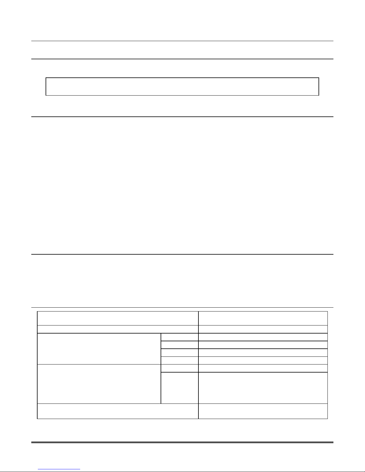
Section 3 Installation
This section contains information necessary to install a MX8000–3EX Digital Alarm Receiver.
IMPORTANT:
Do not connect power to the system until you have read these instructions carefully.
3.1 Quick Start
The following procedure provides a quick start outline that may be used by installers who are familiar with
the installation and programming of the MX8000–3EX receiver. This procedure encompasses the basic
installation and programming steps where the unit will be using mostly default values for operation. For
complete installation procedures, bypass this section and observe the procedures in the balance of this
manual. To perform the quick start installation, proceed as follows:
1. Install any additional line cards into the receiver. (See section 3.7 for additional information.)
2. Power up the receiver by plugging it into an AC outlet. (See section 3.11 for additional information.)
3. Log onto the receiver as the installer. (See section 4.4 for additional information.)
4. Set the receiver time and date. (See section 4.6.6 for additional information.)
5. Enter the program mode by selecting it from the main menu.
6. Select the operation mode for the receiver. (See section 5.3.1 for additional information.)
7. Configure communications and printer ports. (See section 5.3.3 for additional information.)
8. Define device (line card) types and options. (See section 5.4 for additional information.)
9. Select the automation protocol to be used. (See section 5.3.3.5 for additional information.)
10. Exit the program mode and log off the receiver.
3.2 Environmental specifications
• Temperature range is 32º to 120º F (0º to 49º C).
• Indoor use only.
• 85 percent non-condensing humidity.
• Non-corrosive environment.
3.3 Electrical Specifications
Line Voltage:
Fuse: T630mAL, 250VAC, 5 x 20 mm
Current Draw:
(VFD brightness at 50%, all lines on the line cards
in trouble [LEDs On], Auxiliary Relay Off)
A 12 VDC battery does not provide standby time
required by NFPA standards. A UPS (listed for
Protective Signaling Use) must be utilized when
standby power is required. See 5.3.4 for details
on backup battery configuration.
Auxiliary Relay:
The relay field connection must be to a power limited source.
MX8000–3EX 230mA (with no Line Cards)
MX8000-LC3 35mA
Input 10.2 to 14.0 VDC 3 Amp Max. Backup Battery Connection:
Output 13.65 VDC 1.7 Amp charging current
240VAC, 50Hz, 100VA
2.5 Amp @ 24VAC\VDC(Inductive), 0Hz
5 Amp @ 24VAC\VDC(Resistive), 0Hz
3–1
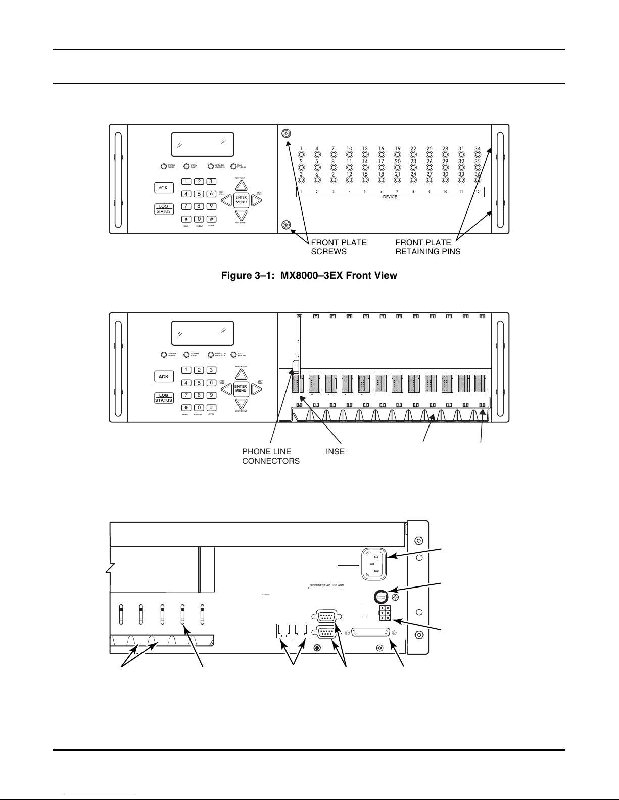
MX8000-3EX Installation and Operation Guide
3.4 Overview
The MX8000–3EX is assembled at the factory. One MX8000-LC3 tri-line card is shipped with the MX8000–
3EX receiver. Follow the procedures described in Section 3.7 to install additional line cards.
31
34
32
35
33
36
ACK
LOG
STATUS
16
17
18
DEVICE
19
23
20
24
21
1
SYSTEM
FAULT
POWER
1
2
4
5
8
7
0
HOME HANGUP
PENDING
LOGGEDIN
PREVEVENT
3
PREV
CALL
6
9
#
LISTEN
ENTER
MENU
NEXTEVENT
NEXT
CALL
CALL
OPERATOR
SYSTEM
2
3
7
14
11
5
8
15
12
6
9
13
10
4
22
28
25
29
26
30
27
8765 12111094321
FRONT PLATE
SCREWS
FRONT PLATE
RETAINING PINS
Figure 3–1: MX8000–3EX Front View
CALL
OPERATOR
SYSTEM
ACK
LOG
STATUS
SYSTEM
FAULT
POWER
1
2
4
5
8
7
0
HOME HANGUP
PENDING
LOGGED IN
PREV EVENT
3
PREV
CALL
6
9
#
LISTEN
NEXT
CALL
ENTER
MENU
NEXT EVENT
PHONE LINE
CONNECTORS
INSERTED
LINE CARD
P5P4P3P2
PHONE LINE
SLOTS
Figure 3–2: MX8000–3EX Front View Without Front Plate Attached
LINE CARD
GUIDES
PHONE
LINE
SLOTS
PHONE LINE
STRAIN RELIEF
TIE-WRAP
HOLDERS
3–2
115 VAC ± 10%
240 VAC ± 10%
50-60 Hz
100 VA
This device has been verified to comply with FCC Rules Part 15.
Operation is subject to the following two conditions: (1) This
device may not cause radio interference, and (2) This device must
accept any interference received including interference that may
cause undesired operation.
This device complies with 47CFR Part 68
Ademco Model MX8000
Registration Number US5GB0T01B46056
Install in accordance with NFPA 72
Central Station Service
SBUS
SBUS
CONNECTORS
WARNING!
HIGH VOLTAGE PRESENT
DISCONNECT AC LINE AND
ALL OTHER CONNECTORS
PROIR TO SERVICING
COM 1
COM 2
SERIAL
PORTS
RELAY RATING
2.5A 48VAC/VDC
PARALLEL
RLY NC
BATT-
BATT+
Figure 3–3: MX8000–3EX Rear View
FUSE
T630 mAL
250VAC
REPLACE ONLY
WITH A FUSE
OF SAME TYPE
UNUSED
RLY NO
RLY COM
PARALLEL
PRINTER
PORT
AC POWER
CORD
CONNECTOR
(SUPERVISED)
FUSE
REMOTE
RELAY/BATTERY
CONNECTOR
00-MX8000-003-V1
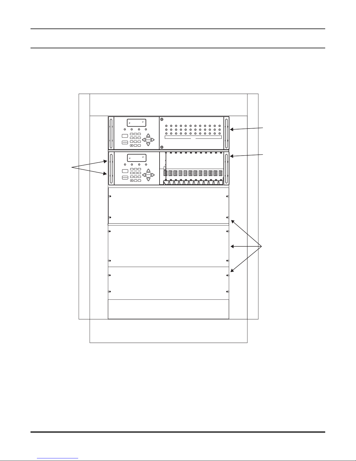
3.5 Rack Mounting
This diagram shows how to mount the MX8000–3EX in a rack enclosure.
31
34
28
22
25
19
13
16
10
4
7
Receiver
Mounting
Screws
(Flat Head
supplied with
receiver)
1
5
8
SYSTEM
POWER
ACK
LOG
STATUS
SYSTEM
POWER
ACK
LOG
STATUS
1
4
7
HOME HANGUP
1
4
7
HOME HANGUP
PENDING
LOGGED IN
FAULT
PREV EVENT
2
3
PREV
CALL
6
5
ENTER
MENU
9
8
#
0
NEXT EVENT
LISTEN
CALL
OPERATOR
SYSTEM
PENDING
LOGGED IN
FAULT
PREV EVENT
3
2
PREV
CALL
6
5
ENTER
MENU
9
8
#
0
NEXT EVENT
LISTEN
CALL
OPERATOR
SYSTEM
2
6
9
3
NEXT
CALL
NEXT
CALL
20
14
17
11
21
15
18
12
DEVICE
P5P4P3P2
32
35
29
23
26
33
36
30
24
27
8765 12111094321
Section 3 – Installation
Model MX8000-3EX
Receiver
Back-up
Model MX8000-3EX
Receiver
(Shown with
faceplate
removed)
Figure 3–4: Rack Mount Enclosure, Front View
Note: All wiring that exits cabinet must be in electrical conduit.
Blank
(Filler)
Panels
3–3
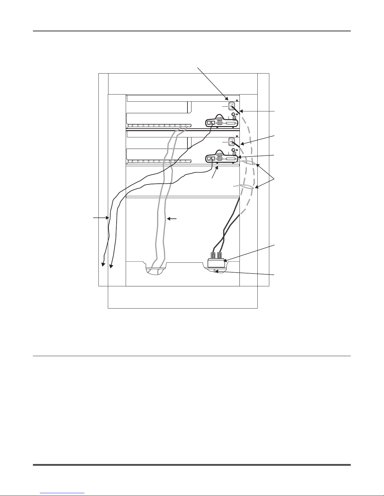
MX8000-3EX Installation and Operation Guide
Power/Non-power limited
and High/Low Voltage Wiring
must be separated by
1/4 inch spacing
This device has been verified to comply with FCC Rules Part 15.
Operation is subject to the following two conditions: (1) This
device may not cause radio interference, and (2) This device must
accept any interference received including interference that may
cause undesired operation.
This device complies with 47CFR Part 68
Ademco Model MX8000
Registration Number US5GB0T01B46056
Install in accordance with NFPA 72
Central Station Service
120 VAC ± 10%
240 VAC ± 10%
50-60 Hz
FUSE
100 VA
2.5A
SLOW BLOW
WARNING!
HIGH VOLTAGE PRESENT
DISCONNECT AC LINE AND
ALL OTHER CONNECTORS
PROIR TO SERVICING
SBUS
REPLACE ONLY
WITH A FUSE
OF SAME TYPE
RELAY RATING
2.5A 48VAC/VDC
COM 1
BATT-
UNUSED
BATT+
RLY NO
RLY NC
RLY COM
PARALLEL
COM 2
Model MX8000-3EX
Receiver
Model MX8000-3EX
120 VAC ± 10%
240 VAC ± 10%
50-60 Hz
FUSE
100 VA
2.5A
SLOW BLOW
WARNING!
HIGH VOLTAGE PRESENT
DISCONNECT AC LINE AND
ALL OTHER CONNECTORS
PROIR TO SERVICING
SBUS
REPLACE ONLY
WITH A FUSE
OF SAME TYPE
RELAY RATING
2.5A 48VAC/VDC
COM 1
UNUSED
BATT-
RLY NO
BATT+
RLY COM
RLY NC
PARALLEL
COM 2
(Backup)
Low Voltage
Power Limited
Shelf or
Support Bracket
(Under Each Unit)
Power limited
wires for SBUS
and Com ports.
Tie-wrap wire
Incoming
Telephone
Lines
to the enclosure
Rear Cabinet Door
(Not Shown)
Figure 3–5: Rack Mount Enclosure, Rear View
Note: All wiring that exits cabinet must be in electrical conduit.
3.6 Hot Swapping of Line Cards
Tie-wrap groups
of wires to the
enclosure
Listed Receptacle
Incoming Line
Power 220/240 VAC,
50Hz
The MX8000–3EX is designed to allow hot swapping (swapping with power applied) line cards in the event
of a line card failure. To hot swap a line card, observe the following procedure:
Note: When hot swapping line cards, only remove and replace one card at a time to avoid hanging up the
system.
1. While holding the front plate, unscrew the two front plate retaining screws located on the front of the
panel. (See Figure 3–1 for front plate retaining screw locations.)
2. Open the MX8000–3EX's front panel by pulling the left side of the front plate slightly forward and then
to the left to remove it from the receiver.
3. Locate the Line Card that you wish to remove.
4. Unplug the telephone line(s). (See Figure 3–6 and Figure 3–7.)
3–4
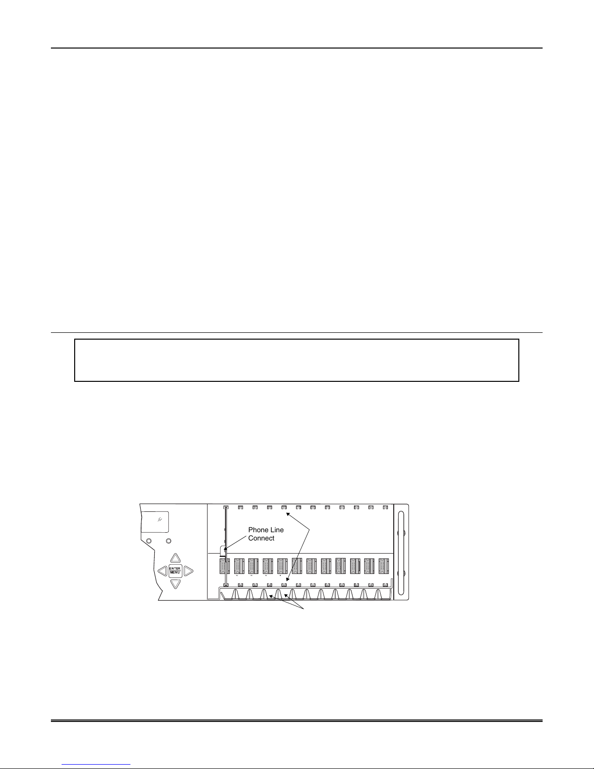
Section 3 – Installation
5. From the front side of the receiver pull the line card straight back. This will pull the card free from the
connector. A message similar to the following will be printed on the MX8000–3EX printer.
05/21/2004 11:42:53AM
System Receiver #: 1 Reference #: 772
Expander Trouble #7
6. When the card is free, slide it carefully out of the receiver.
7. Carefully slide the replacement card into its guides (both top and bottom) until it fits into its connector
at the back of the receiver. Gently push the card as far into the connector as you can. The card is now in
place.
8. Connect telephone line(s). (See Section 3.9 for telephone line installation.) In approximately 60-90
seconds the new line card will be restored into the system with the line card LEDs working normally and
a message similar to the following will be printed on the MX8000–3EX printer.
05/21/2004 11:43:54AM
System Receiver #: 1 Reference #: 774
Expander Trouble Restore #7
9. If you need to hot swap and additional card, repeat steps 1 through 9.
10. Close the MX8000–3EX 's front panel and tighten the front plate retaining screws to hold the front plate
in place.
Note: If a lock up occurs, reboot the system by removing primary power and reapplying it to clear the
condition.
3.7 Line Card Installation
Caution:
To reduce the risk of electrical shock and damage to the receiver, follow these steps in the order
they are listed here.
1. While holding the front plate, unscrew the two front plate retaining screws located on the front of the
panel. (See Figure 3–1 for front plate retaining screw locations.)
2. Open the MX8000–3EX's front panel by pulling the left side of the front plate slightly forward and then
to the left to remove it from the receiver.
3. When the front panel is removed, you will see that there are 12 slots for line cards. The receiver
recognizes each slot by number 1 through 12 (slot one is closest to the keypad and display). It is not
necessary to put line cards in numbered order because the receiver continually polls each slot to see if
existing line cards are functioning and if it is still in its slot. The receiver also looks to see if a new line
card has been added. Figure 3–6 shows where each line card should be placed.
Line Card
Guides
Phone Line Slots
(Front View)
OPERATOR
LOGGED IN
CALL
PENDING
PREV EVENT
PREV
CALL
ENTER
MENU
NEXT EVENT
NEXT
CALL
Phone Line
Connectors
P5P4P3P2
Figure 3–6: Line Card Locations
4. Position the line card as shown in Figure 3–7.
3–5
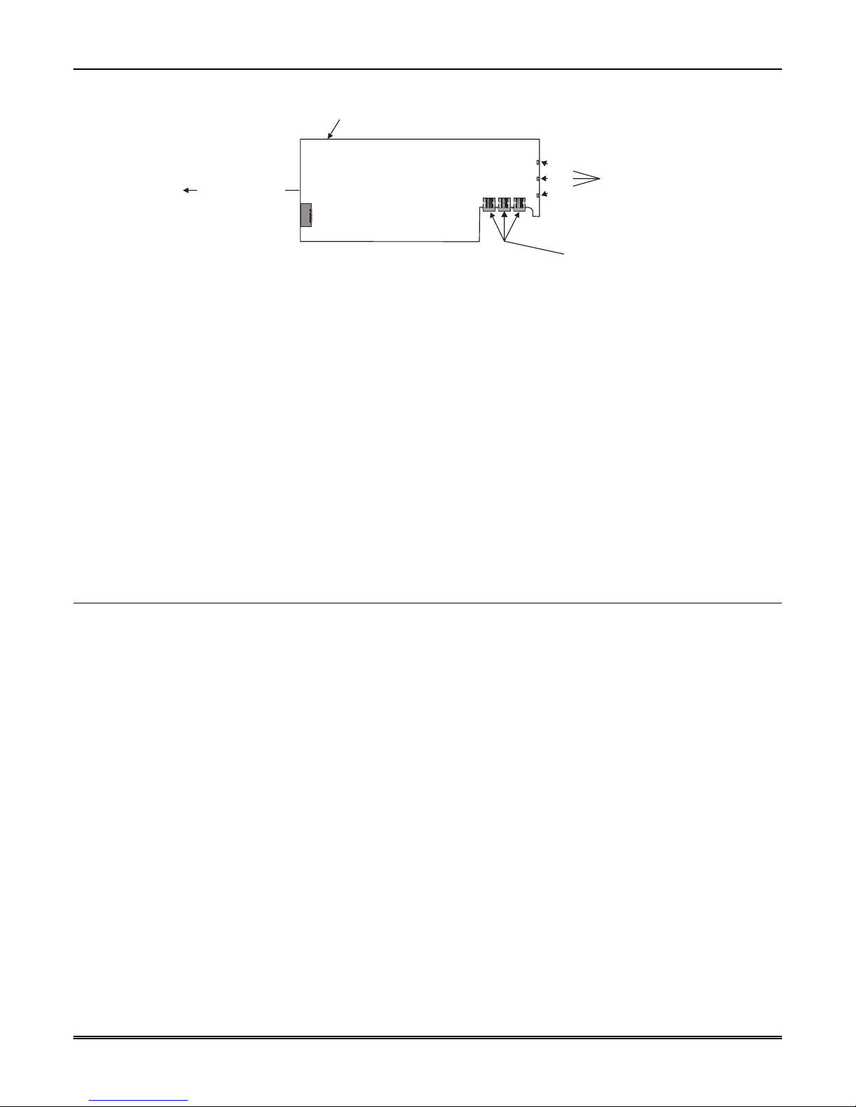
MX8000-3EX Installation and Operation Guide
Top of Line Card
Rear of Card Front of Card
Insert From
Front of MX8000
In This Direction
Model MX8000-LC3
Line 3
Line 2
Line 1
Line 1
Line 2
Line 3
Line Card
Display LEDs
Phone Line
Connectors
(Power Limited
and Supervised)
Figure 3–7: Line Card Position and Components
5. Carefully slide the card into its guides (both top and bottom) until it fits into its connector at the back of
the receiver. Gently push the card as far into the connector as you can. The card is now in place.
6. Connect telephone line(s). (See Section 3.9 for telephone line installation.)
Notes:
•
Use the tie wrap (provided with each line card) on the tie wrap holder to add strain relief to the
telephone lines. See Figure 3–3.
7. Restart the receiver in accordance with the procedures provided in Section 4.6.7.
8. Close the MX8000–3EX's front panel and tighten the front plate retaining screws to hold the front plate
in place. If you are simply replacing a line card with another card of the same type and are using the
same format settings, your installation is now complete. If not continue to the next step.
9. Enter programming mode to select the appropriate handshake configuration. (Go to Section 5.4 for
programming procedure.)
3.8 Removing Line Cards
If you need to remove a card:
1. If you will not be replacing the line card, enter the programming mode to clear the line card from the
system. (See Section 5.4 for programming procedure.)
2. While holding the front plate, unscrew the two front plate retaining screws located on the front of the
panel. (See Figure 3–1 for front plate retaining screw locations.)
3. Open the MX8000–3EX's front panel by pulling the left side of the front plate slightly forward and then
to the left to remove it from the receiver.
4. With the front panel removed, you will see that there are 12 slots for line cards.
5. Locate the Line Card that you wish to remove.
6. Unplug the telephone line(s). (See Figure 3–6 and Figure 3–7.)
7. From the front side of the receiver pull the line card straight back. This will pull the card free from the
connector.
8. When the card is free, slide it carefully out of the receiver.
Note: If replacing a line card with a new one see Section 3.7 to install the new line card.
9. Restart the receiver in accordance with the procedures provided in Section 4.6.7.
10. Close the MX8000–3EX's front panel and tighten the front plate retaining screws to hold the front plate
in place.
3–6

Section 3 – Installation
3.9 Telephone Line Connection
See Figure 3–6 for the location of the phone line inputs. Connections to the MX8000–3EX phone jacks are
made with a standard 7-foot phone cord.
Use the following procedure to connect phone lines to the MX8000–LC3 line cards:
1. While holding the front plate, unscrew the two front plate retaining screws located on the front of the
panel. (See Figure 3–1 for front plate retaining screws locations.)
2. Open the MX8000–3EX's front panel by pulling the left side of the front plate slightly forward and then
to the left to remove it from the receiver.
3. From the back side of the receiver insert the telephone line(s) through the corresponding slot for the
desired line card. (See Figure 3–6 and Figure 3–7 for phone line slot locations.)
4. Gently push them all the way through to the front side of the receiver.
5. Plug the RJ-11 phone connector(s) into the connector(s) on the line card. (See Figure 3–6 and Figure 3–
7.)
Note: Use the tie wrap (provided with each line card) on the tie wrap holder to add strain relief to the
telephone lines. See Figure 3–3.
6. Replace the front panel of the MX8000–3EX receiver by tightening the front plate retaining screws. (See
Figure 3–1 for front plate retaining screws locations.)
3.10 Parallel Printer Connection
The MX8000–3EX Receiver connects to a dot matrix parallel printer such as the Okidata Microline 320. To
connect the printer to the MX8000–3EX receiver follow these steps:
1. Connect the standard parallel printer cable to the parallel printer port on the back of the MX8000–3EX
receiver. (See Figure 3–8.)
2. Connect the other end to the printer’s parallel port.
Note: Make sure that printer power is turned off.
3. Turn the printer power “on”.
115 VAC ± 10%
240 VAC ± 10%
TO PRINTER
WARNING!
HIGH VOLTAGE PRESENT
DISCONNECT AC LINE AND
ALL OTHER CONNECTORS
PROIR TO SERVICING
COM 1
COM 2
50-60 Hz
100 VA
RELAY RATING
2.5A 48VAC/VDC
PARALLEL
FUSE
T630mAL
250 VAC
REPLACE ONLY
WITH A FUSE
OF SAME TYPE
UNUSED
BATT-
RLY NO
BATT+
RLY COM
RLY NC
Figure 3–8: Parallel Printer Cable Connection to MX8000–3EX
3–7
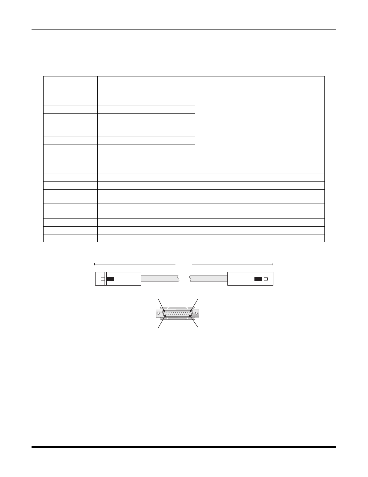
MX8000-3EX Installation and Operation Guide
3.10.1 Printer Cable Pin-Outs
25 pin printer cables are standard items at most electronic stores; however, if you create your own cable, use
the pin description in Table 3–1.
Table 3–1: External Printer Cable Pin Description
MX8000–3EX Pin # Signal Direction Description
1 Data Strobe (Low) Out A low strobe pulse to read data into the printer. The
pulse width is greater than 0.5 microseconds.
2 Data Bit 1 Out
3 Data Bit 2 Out
4 Data Bit 3 Out
5 Data Bit 4 Out
6 Data Bit 5 Out
7 Data Bit 6 Out
8 Data Bit 7 Out
9 Data Bit 8 Out
10 /AckNlg In A low pulse from the printer signals the control that
11 Busy In A high level indicates that the printer is busy.
12 Paper Empty In A high level indicates that the printer is out of paper.
13 Select In A low level indicates the printer is offline or in an
14 Not used - 15 Not used - 16 Logic ground - Logic ground for printer
17 Not used - 18 to 25 Logic Ground - Ground return for data lines.
These signals represent information of the first to
eighth bits of parallel data. Each signal is at high
level when the data is logic 1 and low when it is
logic 0.
the printer is ready for additional data.
error condition.
Figure 3–9 shows the wiring sequence of this connector.
10.0'
Receiver
Pin 1 Pin 13
MX8000
Pin 25Pin 14
NOTE:
Printer
10' is the
maximum
recommended
cable length.
Figure 3–9: Wiring Sequence For Parallel Printer Port Interface
3.10.2 Com Ports 1 and 2
Com Ports 1 and 2 are serial communication ports that (through a null modem cable) can be used to
communicate to other serial communication devices. Com Port 1 is the only serial communications port that
can be used with the automation computer (see Section 3.13). A standard null modem cable can be used to
connect Com Port 1 or 2 to another serial device such as a printer or a PC. Figure 3–14 and Figure 3–15
show the pin-outs for a null modem cable. See Section 5.3.2.8 to configure the Com Port 1 and Com Port 2.
Note: Com Port 1 and 2 are for ancillary use only.
3–8
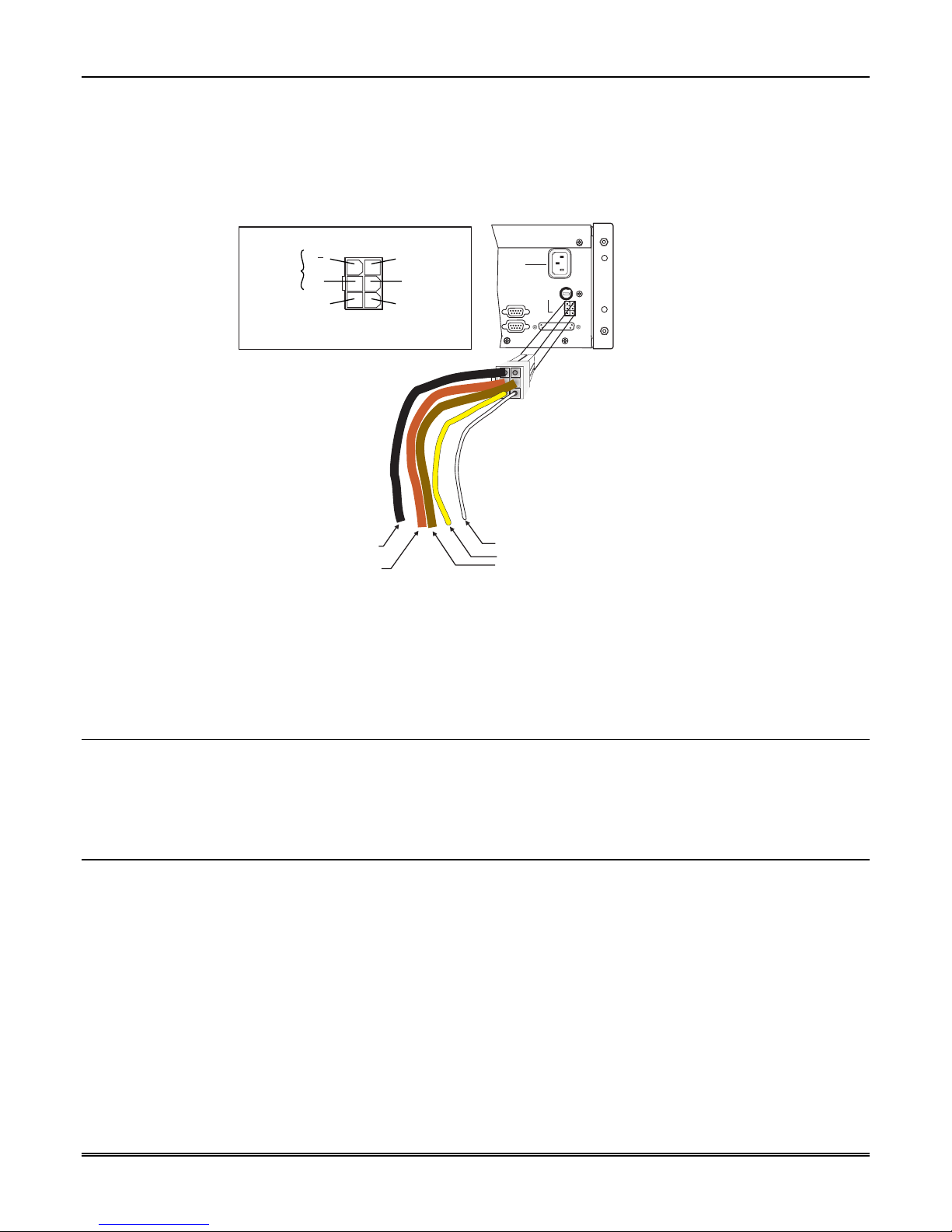
Section 3 – Installation
3.10.3 Remote Alert Output
1. Plug the Battery/Relay wiring harness onto the connector on the back of the MX8000–3EX receiver. (See
Figure 3–10.)
Note: The remote alert output is a form C relay with a normally open or a normally closed wire.
2. Connect the white wire to common.
EXTERNAL
BATTERY
RELAY N.C.
B
B+
UNUSED
RELAY N.O.
RELAY COM.
REMOTE
ANNUNCIATOR
Black: Battery Negative
Red: Battery Positive
Figure 3–10: MX8000–3EX Remote Alert Output/Backup Battery Connection
3. Use the Yellow wire for a normally closed circuit
Or
Use the Brown wire for a normally open circuit.
115 VAC ± 10%
240 VAC ± 10%
50-60 Hz
FUSE
100 VA
T630mAL
RELAY RATING
2.5A 48VAC/VDC
250 VAC
REPLACE ONLY
WITH A FUSE
OF SAME TYPE
BATT-
UNUSED
BATT+
RLY NO
RLY COM
RLY NC
PARALLEL
WARNING!
HIGH VOLTAGE PRESENT
DISCONNECT AC LINE AND
ALL OTHER CONNECTORS
PROIR TO SERVICING
COM 1
COM 2
Note:
A 1/4 inch spacing must be
maintained between the battery
wires and the relay wires.
If this spacing cannot be
maintained use non-power
limited wiring methods as
described in NFPA 70
National Electrical Code.
The relay can only be used
with a listed power limited
resistive load, class 2 or
class 3 supply.
White: Relay Common
Yellow: Relay N.C.
Brown: Relay N.O.
3.11 AC Power Cord Connection
1. Connect the appropriate end of the power cord into its receptacle on the back of the MX8000–3EX.
2. Plug the three-pronged end of the power cord into an earth-grounded 220-240 VAC 50 Hz. The outlet
should be unswitched, so that power remains on 24 hours a day.
3.12 Battery Connection
To install the backup battery, follow these steps:
1. Plug the Battery/Relay wiring harness onto the connector on the back of the MX8000–3EX receiver. (See
Figure 3–11.)
2. Connect the RED terminal to the positive (+) side of the battery.
3. Connect the BLACK terminal to the negative (-) side of the battery.
Note: Incorrect polarity can damage the battery and the MX8000–3EX.
3–9
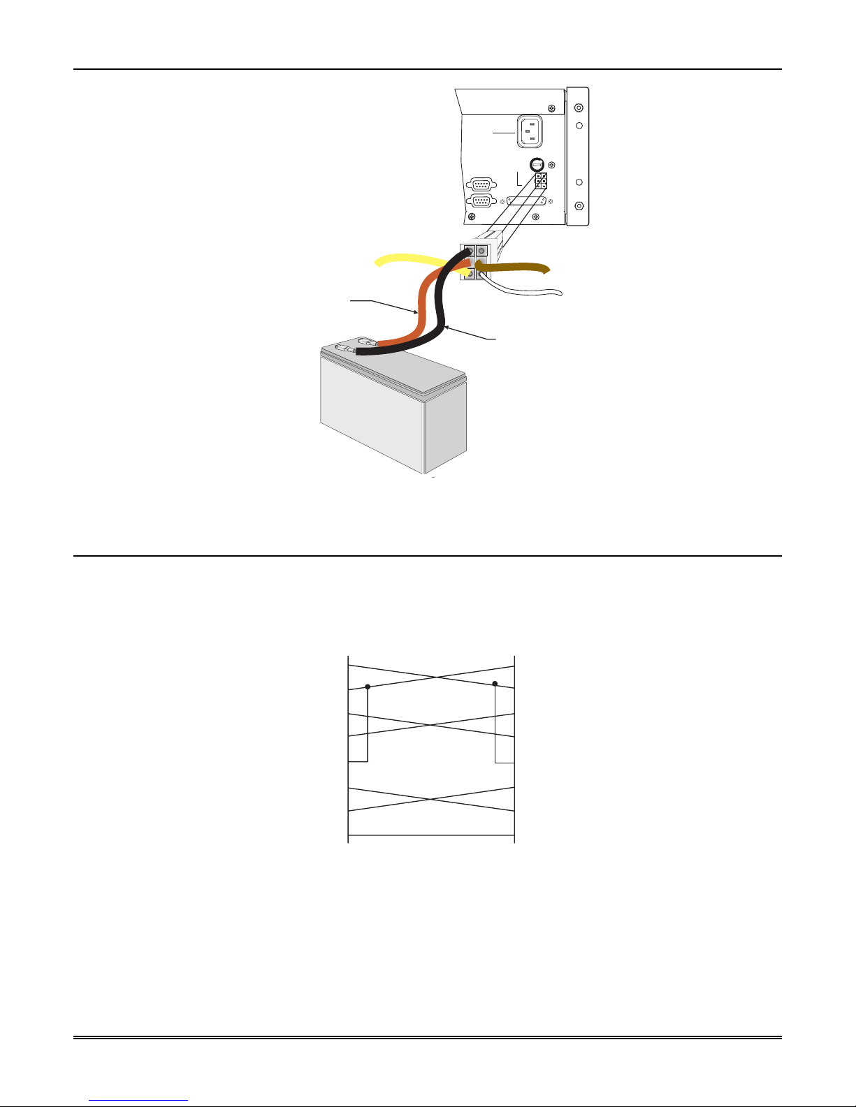
MX8000-3EX Installation and Operation Guide
Red: Battery Positive
WARNING!
HIGH VOLTAGE PRESENT
DISCONNECT AC LINE AND
ALL OTHER CONNECTORS
PROIR TO SERVICING
COM 1
COM 2
115 VAC ± 10%
240 VAC ± 10%
50-60 Hz
100 VA
RELAY RATING
2.5A 48VAC/VDC
PARALLEL
FUSE
T630mAL
250 VAC
REPLACE ONLY
WITH A FUSE
OF SAME TYPE
UNUSED
BATT-
RLY NO
BATT+
RLY COM
RLY NC
+
-
Backup Battery
Black: Battery Negative
Replace Battery
Every 5 Years
Figure 3–11: Battery Connections
3.13 Automation Computer Connection
An automation computer can be connected to Com Port 1 on the MX8000–3EX receiver. Com Port 1 is a 9pin DTE port. Refer to Section 8 for details on automation communication protocols. The diagrams below
describe some of the cable options.
MX8000 9-PIN DTE 25-PIN DTE
4 DTR
6 DSR
7 RTS
8 CTS
DTR 20
DSR 6
RTS 4
CTS 5
Figure 3–12: 25-Pin Null Modem Cable Connection
3–10
1 DCD
3 TXD
2 RXD
5 GND
DCD 8
TXD 2
RXD 3
GND 7
 Loading...