

Page 1
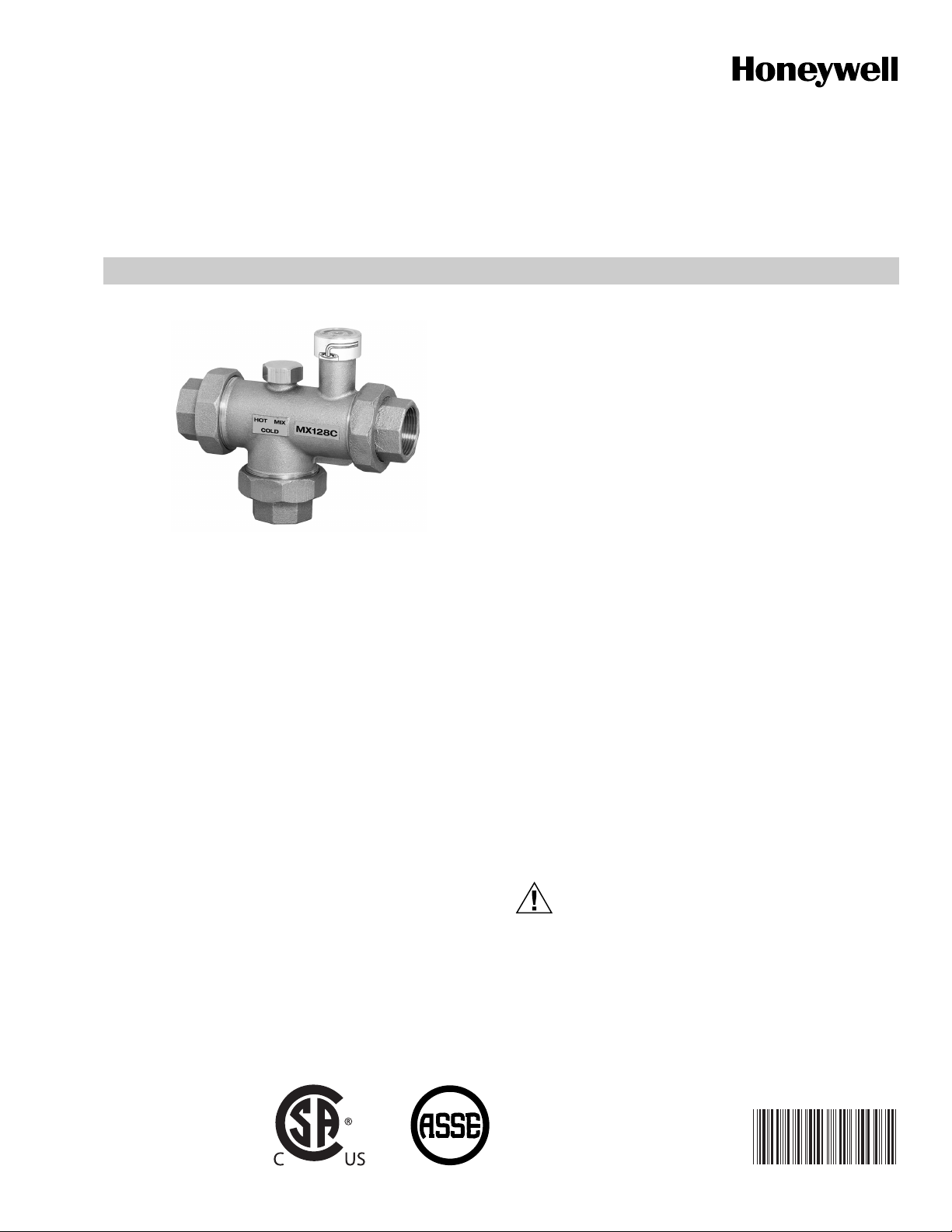
MX Series Valves
LARGE FLOW PROPORTIONAL THERMOSTATIC MIXING
OR DIVERTING VALVE
PRODUCT SPECIFICATIONS
• Dual purpose mixing or diverting valve.
• Constant water temperature under different operating
conditions.
• Proportional valve (control of hot and cold water).
• Flow reduction in seconds if cold water supply is
uninterrupted.
• Temperature adjustable.
• Unions / tailpieces connections included.
• Install in any position, heat trapping not required.
• Recirculation connection for fast response.
APPLICATION
Any application requiring accurate control of water
temperature based on mixing of hot and cold water, such as:
Domestic water for hotels, schools, hospitals, nursing homes,
offices, public facilities, commercial and industrial buildings,
space heating, central distribution systems, heat pump
systems, radiant floor heating, combo systems and industrial
applications.
Installer:
1. Fill in measured discharge temperature on CAUTION
label.
2. Attach CAUTION label to MX series valve.
3. Explain CAUTION label to owner.
4. Leave this instruction sheet with owner or on the job
site.
Benefits
The MX Series thermostatic mixing valve provides energy
savings, increased comfort and safety for the user.
• Brass / stainless steel construction.
®
• Water surfaces Teflon
deposits.
• Allen wrench for temperature adjustment included.
• Maximum pressure differential between hot and cold
ports is 7 psi.
• ASSE 1017 tested and certified.
• CSA approved.
coated to prevent lime
OPERATION
Automatic operation is provided by the thermostatic element.
Element will control hot and cold supply based on valve
setting. If cold water is shut off, valve reduces mixed flow in
seconds (speed/residual flow rates vary by size).
CAUTION
For domestic water application use “C” model, set
temperature to not exceed 120° F (49° C) for safety.
Do not override calibration. Test temperature with
thermometers.
PRODUCT DATA
Contents
Application.........................................................................1
Product Specification......................................................... 1
Operation...........................................................................1
Ordering Information .........................................................2
Typical Installation Diagrams.............................................3
62-3079
Page 2
MX SERIES VALVES
in Lbs
(kg)
SIZE
MX127-130
D MINIMUM
A
M23693
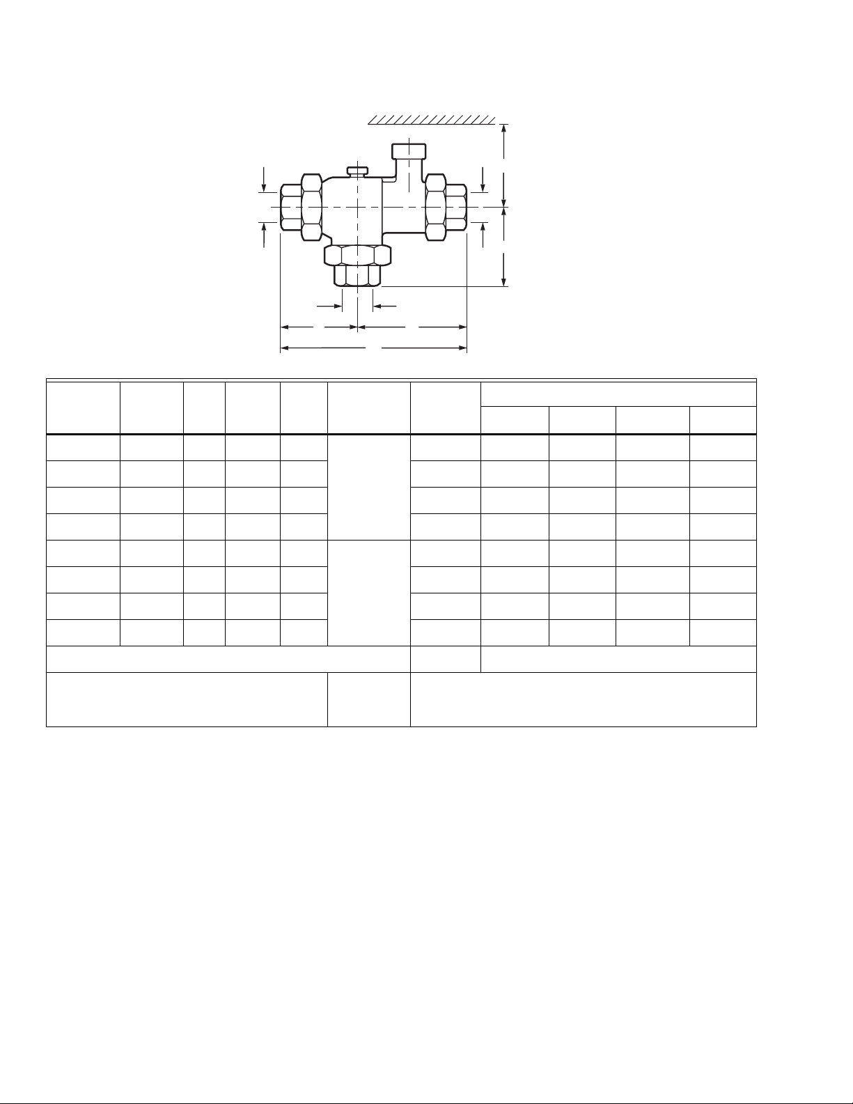
Dimensions in inches (mm)
AB C D
SIZE
H
C
C
Product
Number
Size
NPT
Min.
Flow
C
(GPM)
v
GPM
@ 30
psi
Temp.
Range
MX 127 1 in. 4.0 1.0 22 110°-150° F
M
SIZE
BA
Weight
3.6 (1.6) 2.8 (66) 3.7 (94) 6.5 (165) 6.0 (152)
(43°-65° C)
MX 128 1-1/4 in. 9.3 2.5 50 6.4 (2.9) 3.3 (84) 4.4 (112) 7.7 (196) 6.9 (175)
MX 129 1-1/2 in. 13.5 3.5 75 8.4 (3.8) 3.6 (91) 5.0 (127) 8.6 (218) 7.0 (178)
MX 130 2 in. 18.0 5.0 100 13.1 (5.9) 4.2 (107) 5.8 (147) 10.0 (254) 7.3 (185)
MX 127C* 1 in. 4.0 1.0 22 90°-120° F
3.7 (1.7) 2.8 (66) 3.7 (94) 6.5 (165) 6.0 (152)
(32°-49° C)
MX 128C* 1-1/4 in. 9.3 2.5 50 6.5 (2.9) 3.3 (84) 4.4 (112) 7.7 (196) 6.9 (175)
MX 129C* 1-1/2 in. 13.5 3.5 75 8.5 (3.9) 3.6 (91) 5.0 (127) 8.6 (218) 7.0 (178)
MX 130C* 2 in. 18.0 5.0 100 13.2 (6.0) 4.2 (107) 5.8 (147) 10.0 (254) 7.3 (185)
MX 050-RP Recirculation Adapter Kit 0.2 (0.1)
* Includes 1/2 in. recirculation adapter.
Maximum Temperature 200° F (93° C)
Maximum working Pressure 150 psi (1034 kPa).
Minimum temperature difference between hot and mix
should be 10° F (6° C).
Use C models only for domestic water.
ORDERING INFORMATION
When purchasing replacement and modernization products from your TRADELINE® wholesaler or distributor, refer to the
TRADELINE
If you have additional questions, need further information, or would like to comment on our products or services, please write or
phone:
1. Your local Honeywell Automation and Control Products Sales Office (check white pages of your phone directory).
2. Honeywell Customer Care
In Canada—Honeywell Limited/Honeywell Limitée, 35 Dynamic Drive, Toronto, Ontario M1V 4Z9.
International Sales and Service Offices in all principal cities of the world. Manufacturing in Australia, Canada, Finland, France,
Germany, Japan, Mexico, Netherlands, Spain, Taiwan, United Kingdom, U.S.A.
®
Catalog or price sheets for complete ordering number.
1885 Douglas Drive North
Minneapolis, Minnesota 55422-4386
62-3079 2
Page 3
Service
To remove dirt, flush valve. Top remove calcium deposits, soak
valve in vinegar for 24 and flush or contact factory for
assistance. Do not attempt to field repair this calibrated valve.
Temperature Selection
The MX Series Valves are made in two ranges: 110°-150° F
(43°-66° C) and 90°-120° F (32°-49° C). The factory setting is
130° F (54° C), and 105° F (41° C) respectively. Change
temperature setting with an Allen wrench, which is included;
3/16 for MX 127 or a 5/16 for MX 128, MX 129 and MX 130.
Punch through the center of the temperature range label. By
turning the screw clockwise, the mix temperature increases
(counterclockwise, it decreases). Each complete turn with the
Allen wrench changes the temperature as follows: MX 127
(1 in.); 11° F (6° C), MX 128 (1-1/4 in.), MX 129 (1-1/2 in.) and
MX 130 (2 in.), 7° F (4° C). Do not operate valve at
temperatures outside of its calibrated range of 110°-150° F
(43°-66° C) or 90°-120° F (32°-49° C). Use a thermometer to
verify temperature.
TYPICAL INSTALLATION DIAGRAMS
MX SERIES VALVES
PUMP
T
TO DISHWASHER
IF PERMITTED
BY CODES
(1)
MX SERIES
VALV E
M
(1)
H
C
8
(203)
MAX
WATER
HEATER
RECIRCULATION
(1)
HEAT
TRAP
6
(152)
ALLOWABLE
SERVICE
VALV E
LOCATION
EXPANSION
TAN K
COLD
WATER
SUPPLY
V
M23687
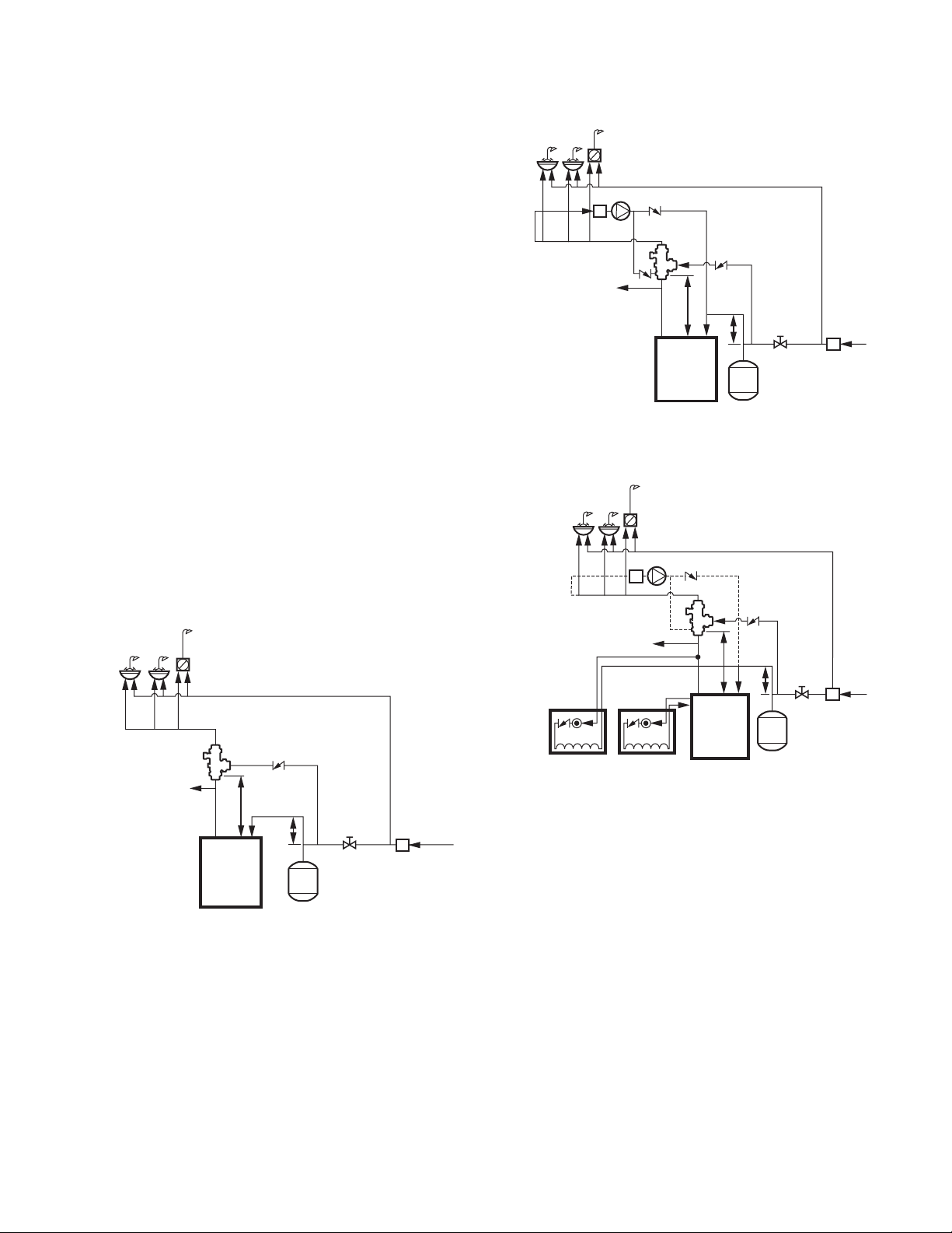
Fig. 2. Heater with recirculation in inches (mm).
Domestic Water Mixing
Use when water temperature produced by heater is hotter that
desired at point of use. Many codes require that water supplied
to the system be limited to 120° F (49° C) max.
MX SERIES
VALV E
M
C
TO DISHWASHER
IF PERMITTED
BY CODES
H
8
(203)
MAX
WATER
HEATER
Fig. 1. Water heater without recirculation in inches (mm).
(1)
HEAT TRAP
6
(152)
ALLOWABLE
SERVICE
VALV E
LOCATION
EXPANSION
TAN K
V
COLD
WATER
SUPPLY
M23686
WATER
USE
FIXTURES
FAN COIL
CONNECTIONS TO
CONVENTIONAL
WATER HEATER
TO DISHWASHER
IF PERMITTED
BY CODES
PUMP
T
FAN COIL
CONNECTIONS
TO SIDE TAP
WATER HEATER
(1)
M
H
C
8
(203)
MAX
WATER
HEATER
RECIRCULATION (IF
NO RECIRULATION
IS REQUIRED OMIT
DASHED PIPING)
(1)
ALLOWABLE
HEAT
SERVICE
TRAP
VALV E
6
LOCATION
(152)
EXPANSION
TAN K
COLD
WATER
SUPPLY
V
M23688
Fig. 3. Water heater is used for domestic water and space
heating in inches (mm).
1.= Check Valve.
2. = Alternate Pump Location.
V.= Any device which turns the domestic water system into a
closed system, such as backflow preventers, check valves or
pressure reducing valves.
NOTE: “V” is optional depending on local codes. If a “V” type
valve is used, it is mandatory that a thermal expansion tank be installed as shown.Otherwise dangerously high pressures could result or water heater
safety relief valve will frequently expel water. If a “V”
device is not used, a thermal expansion tank is not
required.
3 62-3079
Page 4
MX SERIES VALVES
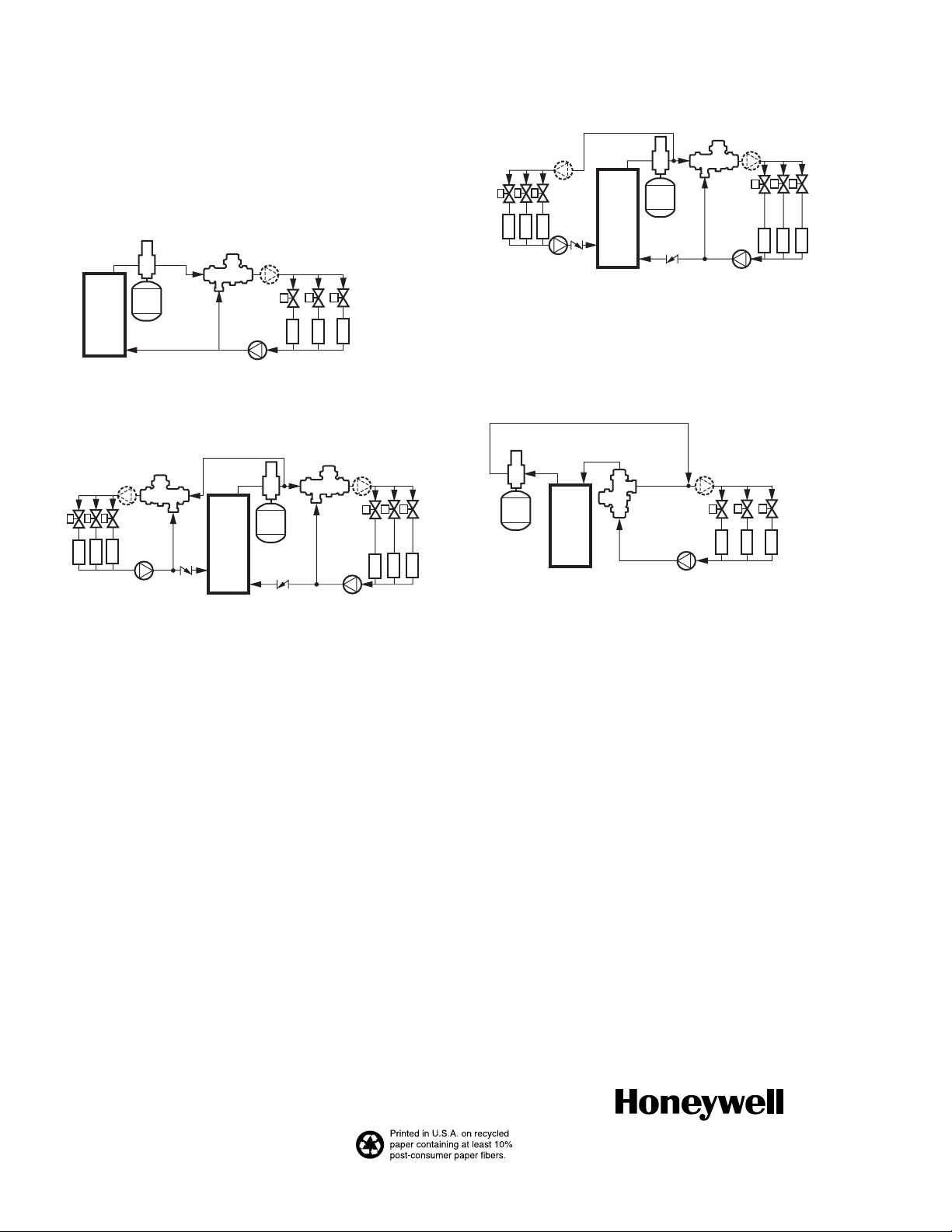
Space Heating
Boiler must operate at a water temperature higher than
desired temperature in the heating system in order to perform
at maximum efficiency. Example: Radiant floor heating.
Mixing Applications (Constant Supply Temperature)
SUPERVENT
HEAT
SOURCE
(BOILER,
WATER
HEATER,
ETC.)
MX SERIES VALVE
M
H
EXPANSION
TAN K
C
A
PUMP
Fig. 4. Single loop.
(2)
Z
Z
Z
ZONE VALVES
RADIANT
FLOOR LOOP
M23689
EXPANSION
TAN K
(1)
MX SERIES VALVE
M
H
C
A
PUMP
ZONE
(2)
VALV ES
Z
Z
Z
RADIANT
FLOOR
LOOP
M23691
Z
Z
BASEBOARD
LOOP
SUPERVENT
(2)
Z
PUMP
HEAT
SOURCE
(BOILER,
WATER
(1)
HEATER,
ETC.)
Fig. 6. Multiple Loops. One loop operates at boiler water
temperature and MX Series loops at lower temperature.
Diverting Application
EXPANSION
TAN K
(1)
MX SERIES VALVE
M
H
C
A
PUMP
ZONE
(2)
VALV ES
Z
Z
Z
RADIANT
FLOOR
LOOP
M23690
Z
RADIENT
FLOOR
LOOP
Z
(2)
Z
MX SERIES VALVE
M
H
C
(1)
A
PUMP
SUPERVENT
HEAT
SOURCE
(BOILER,
WATER
HEATER,
ETC.)
Fig. 5. Multiple loops. Each loop operates at a different
temperature.
TRADELINE® IS A REGISTERED TRADEMARK OF HONEYWELL INC.
®
EFLON
T
IS A REGISTERED TRADEMARK OF E.I. DU PONT DE NEMOURS AND COMPANY.
SUPERVENT
EXPANSION
TAN K
C
H
HEAT
SOURCE
(BOILER,
WATER
HEATER,
ETC.)
MX SERIES
VALV E
H
C
M
PUMP
(2)
ZONE
VALV ES
Z
Z
Z
RADIANT
FLOOR
LOOP
M23692
Fig. 7. Single loop. For multiple loops see Mixing
Applications.
Automation and Control Solutions
Honeywell International Inc. Honeywell Limited-Honeywell Limitée
1985 Douglas Drive North 35 Dynamic Drive
Golden Valley, MN 55422 Toronto, Ontario M1V 4Z9
customer.honeywell.com
® U.S. Registered Trademark
© 2007 Honeywell International Inc.
62-3079 J.I. 01-07
 Loading...