

Page 1
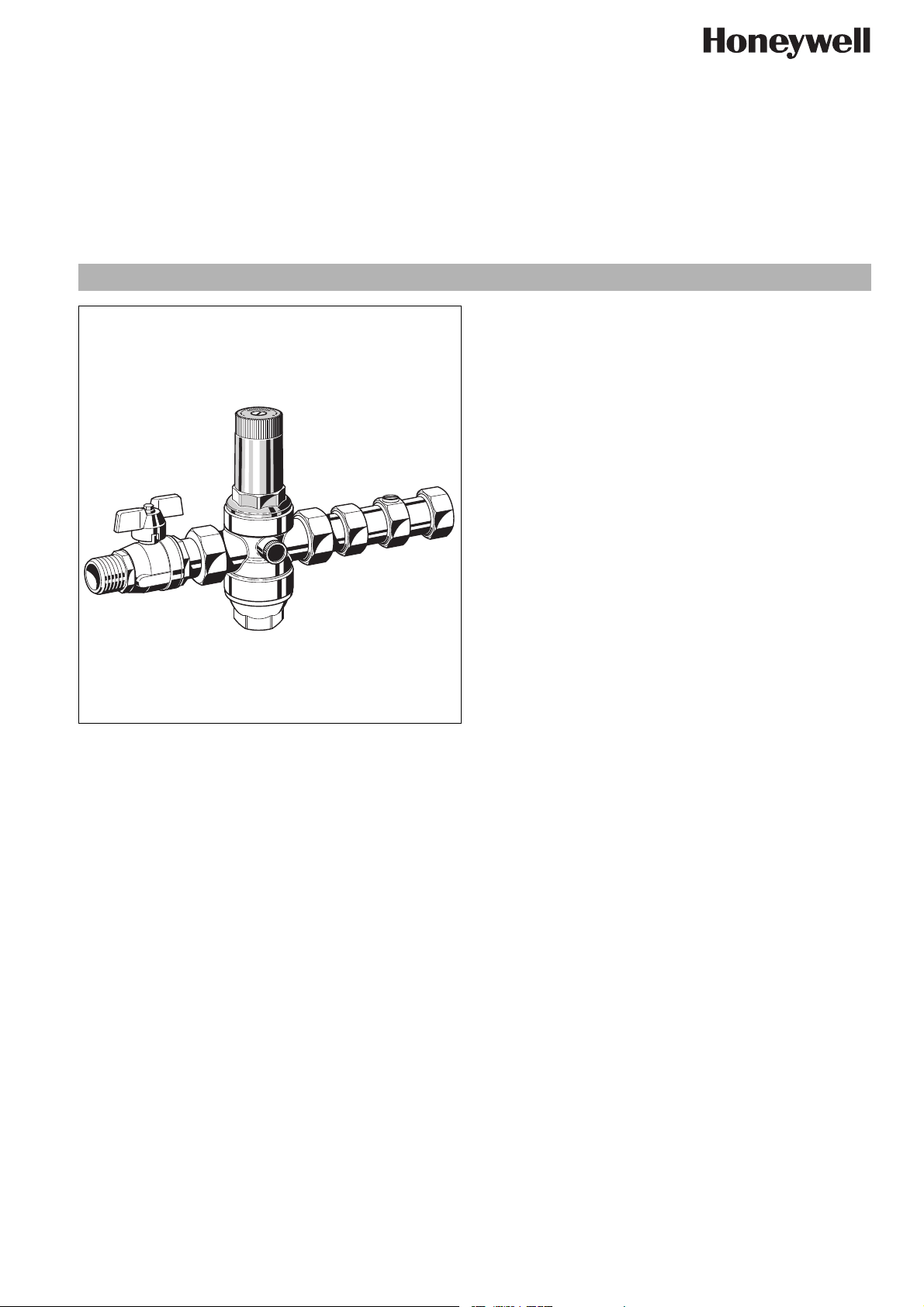
High pressure reducing valve combination
Construction
The pressure reducing valve combination comprises:
• Housing with pressure gauge connections on both sides
• Shutoff valve on inlet
• Double check valve on outlet
• Valve insert complete with diaphragm and valve seat
• Fine filter with 0.16 mm mesh
• Spring bonnet with adjustment knob
•Filter bowl
• Adjustment spring
• Pressure gauge not included (see accessories)
Materials
• Dezincification resistant brass housing
• Brass shutoff valve
• Brass and high-quality synthetic material double check valve
• High-quality synthetic material valve insert
• Stainless steel fine filter mesh
EN0H-1041GE23 R1108 • Subject to change
• High-quality synthetic material spring bonnet with adjustment
knob and setting scale
• Brass filter bowl
• Spring steel adjustment spring
• Fibre-reinforced NBR diaphragm
• NBR seals
MTA06-H
with balanced seat
Product specification sheet
Application
The pressure reducing valve combination combines a shutoff
valve, a pressure reducing valve and a double check valve in one
appliance.
This all-in-one device saves space and simplifies the installation.
The combination protects household water installations against
excessive pressure from the supply. The assembly can also be
used for industrial or commercial applications within the range of
its specification.
By installing a pressure reducing valve, pressurisation damage is
avoided and water consumption is reduced.
The set pressure is also maintained constant, even when there is
wide inlet pressure fluctuation.
Reduction of the operating pressure and maintaining it at a
constant level minimizes flow noise in the installation.
The double check valve protects the mains water system against
back pressure, back flow and back syphonage of health threatening liquids.
Special Features
• WRAS-approval requested (Pressure reducing valve and
double check valve)
• Especially compact because shutoff valve, pressure reducing
valve and double check valve are combined in one unit
• The outlet pressure is set by turning the adjustment knob
• The set pressure is directly indicated on the set point scale
• The adjustment spring is not in contact with the potable water
• The valve insert is of high quality synthetic material and can
be fully exchanged
• Integral fine filter
• Inlet pressure balancing - fluctuating inlet pressure does not
influence outlet pressure
• Meets KTW recommendations for potable water
Range of Application
Medium Water, compressed air* and nitrogen* in consi-
deration of valid standards (e.g. DIN EN 12502)
Inlet pressure max. 25 bar
Outlet pressure 1.5-12 bar (preset 5 bar)
*
As part of an installation being approved according to PED requirements, this
product must also be certified.
Technical Data
Operating temperature max. 70°C
(WRAS for cold water use only)
Minimum pressure drop 1 bar
3
Connection size
/4" and 1"
www.honeywell.com 1
Page 2
MTA06-H High pressure reducing valve combination
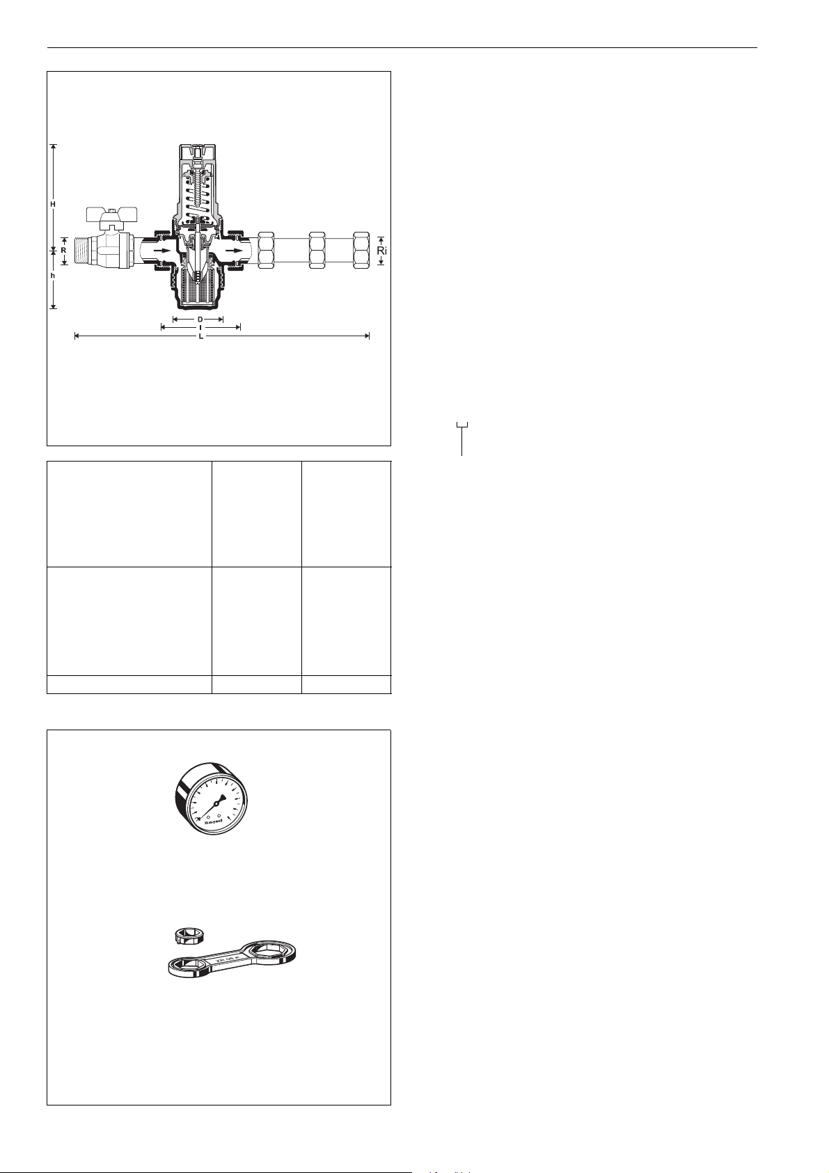
Connection size R
Ri
Nominal size
diameter
DN 20 25
Weight approx.
kg
Dimensions mm
L 289.5 332
H 96 140.5
h56 78
D54 72
-value 2.7 6.3
k
vs
3
/4"1"
3
/4"1"
1.40 2.12
l 90 100
Method of Operation
The pressure reducing combination combines a shutoff valve, a
pressure reducing valve and a check valve in one appliance.
Spring loaded pressure reducing valves operate by means of a
force equalising system. The force of a diaphragm operates
against the force of an adjustment spring. If the outlet pressure
and therefore diaphragm force fall because water is drawn, the
then greater force of the spring causes the valve to open. The
outlet pressure then increases until the forces between the
diaphragm and the spring are equal again.
The inlet pressure has no influence in either opening or closing of
the valve. Because of this, inlet pressure fluctuation does not
influence the outlet pressure, thus providing inlet pressure balancing.
Check valves have a moving seal disc which is lifted off the seat
by a greater or lesser amount depending on the flow rate through
the valve. If the flow falls towards zero, then the spring pushes
the disc back onto the seat and seals the waterway.
Options
MTA06-... H = With threaded connections (inlet male, outlet
female thread, brass filter bowl up to 70°C)
Connection size
2 www.honeywell.com
4
2
r
ba
0
M07M
ZR06K
Accessories
M07M Pressure gauge
6
8
10
Housing diameter 63 mm, rear connection thread
1
/4". Ranges: 0 - 4, 0 - 10, 0 - 16 or 0 - 25 bar.
G
Please indicate upper value of pressure range when
ordering
ZR06K Double ring wrench
For removal of spring bonnet and filter bowl
EN0H-1041GE23 R1108 • Subject to change
Page 3

Installation Example
3
Connection size R
/4"1"
DN 20 25
W* mm 55 60
* Minimum distance from wall to centre line of pipework
MTA06-H High pressure reducing valve combination
Installation Guidelines
• Install in horizontal pipework with filter bowl downwards.
• The installation location should be protected against frost
and be easily accessible
o Pressure gauge can be read off easily
o Simplified maintenance and cleaning
• For residential applications where maximum protection
against dirt is required, install a fine filter upstream of the
pressure reducing valve
• Provide a straight section of pipework of at least five times the
nominal valve size after the pressure reducing valve (in accordance with DIN 1988, Part 5)
Flow Diagram
Typical Applications
The pressure reducing valve combinations are foreseen for the
point of entry of apartments, offices or any other multiple unit
building. They are particularly suitable for all types of household
applications to comply with standards and for industrial and
commercial use within the limits of their specifications.
Pressure reducing valves should be installed:
• To comply with standards and where space is limited, for
example in modernisation of old buildings
• If the static pressure exceeds the maximum permissible value
for the system
• As protection against noise if the static pressure at take off
points exceeds 5.0 bar (DIN 4109: Noise protection in high
buildings)
• If several pressure zones are required when a pressurisation
system is used (pressure reducers on each storey of a building)
• If pressure fluctuations in the downstream system must be
avoided
• To achieve constant inlet and outlet pressures on pumped
pressure boosting systems
EN0H-1041GE23 R1108 • Subject to change
www.honeywell.com 3
Page 4

MTA06-H High pressure reducing valve combination
1
5
4
2
Spare Parts
High pressure reducing valve combination MTA06H,
from 2008 onwards
No. Description Dimension Part No.
1 Spring bonnet
complete
2 Valve insert complete
3
/4" 0900227
1" 0900228
3
/4"D06FA-1/2
(without filter) 1" D06FA-1A
3 Shutoff valve
3
/4" 2193100
1" 2193200
4 Union seal washer
3
/4" 0901444
(10 pcs.) 1" 0901445
2
3
6
7
8
5 Blanking plug
with O-ring R
1
/4"
(5 pcs.)
6 Replacement filter
insert
7 O-ring
3
/4" ES06F-1/2A
1" ES06F-1A
3
/4" 0901246
S06K-1/4
(10 pcs.) 1" 0901247
8 Brass filter bowl with
3
/4" SM06T-1/2
O-ring 1" SM06T-1A
Automation and Control Solutions
Honeywell GmbH
Hardhofweg
D-74821 Mosbach
Phone: (49) 6261 810
Fax: (49) 6261 81309
http://europe.hbc.honeywell.com
www.honeywell.com
Manufactured for and on behalf of the
Environmental and Combustion Controls Division
of Honeywell Technologies Sàrl, Rolle, Z.A. La
Pièce 16, Switzerland by its Authorised Representative Honeywell GmbH
EN0H-1041GE23 R1108
Subject to change
© 2008 Honeywell GmbH
 Loading...