

Page 1
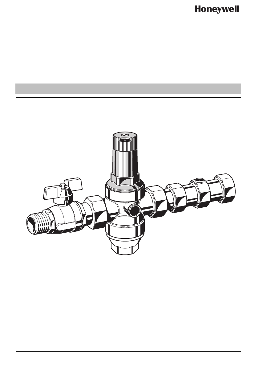
MTA06 / MTA06H
Installation instructions
EB-MTA06 Rev. C
Pressure Reducing Valve Combination
Page 2
7.2
9.2.1
8.1
9.
5.
8.
7.
1.
6.
4.
10.
3.
1.
9.3
4.
5.
9.
5.
6.
1.
7.
3.
6.
4.
10.
7.
8.
10.
13.
9.
12.
9.4
8.
1.
3.
6.
8.
4.
5.
11.
11.
9.
3.
MU1H-1037GE23 R1208 Honeywell GmbH
Page 3

GB
1. Safety Guidelines
1. Follow the installation instructions.
2. Use the appliance
• according to its intended use
• in good condition
• with due regard to safety and risk of danger.
3. Note that the appliance is exclusively for use in the applications detailed in these installation instructions. Any other
use will not be considered to comply with requirements
and would invalidate the warranty.
4. Please take note that any assembly, commissioning,
servicing and adjustment work may only be carried out by
authorized persons.
5. Immediately rectify any malfunctions which may influence
safety.
2. Functional description
The pressure reducing combination combines a shutoff valve,
a pressure reducing valve and a check valve in one appliance.
Spring loaded pressure reducing valves operate by means of
a force equalising system. The force of a diaphragm operates
against the force of an adjustment spring. If the outlet pressure and therefore diaphragm force fall because water is
drawn, the then greater force of the spring causes the valve
to open. The outlet pressure then increases until the forces
between the diaphragm and the spring are equal again.
The inlet pressure has no influence in either opening or
closing of the valve. Because of this, inlet pressure fluctuation
does not influence the outlet pressure, thus providing inlet
pressure balancing.
Check valves have a moving seal disc which is lifted off the
seat by a greater or lesser amount depending on the flow rate
through the valve. If the flow falls towards zero, then the
spring pushes the disc back onto the seat and seals the
waterway.
3. Application
Medium Water, compressed air* and nitrogen* in
consideration of valid standards (e.g. DIN
EN 12502)
Inlet pressure max. 16 bar (MTA06-B)
max. 25 bar (MTA06-H)
Outlet pressure 1.5-6 bar (preset 3bar) (MTA06-B)
*
As part of an installation being approved according to PED require-
ments, this product must also be certified.
1.5-12 bar (preset 5bar) (MTA06-H)
5. Scope of delivery
The pressure reducing valve combination comprises:
• Housing with pressure gauge connections on both sides
• Shutoff valve on inlet
• Double check valve on outlet
• Valve insert complete with diaphragm and valve seat
• Fine filter with 0.16 mm mesh
• Spring bonnet with adjustment knob and setting scale
(setting scale with MTA06-B only)
•Filter bowl
• Adjustment spring
• Pressure gauge not included (see accessories)
6. Options
MTA06-... B = With threaded connections (inlet male,
outlet female thread)
MTA06-... H = With threaded connections (inlet male,
outlet female thread, brass filter bowl up to
70°C)
7. Assembly
7.1 Installations Guidelines
Ensure that both connections to the PRV are tightened prior
to filling and pressurization
• Install in horizontal pipework with filter bowl downwards.
• The installation location should be protected against frost
and be easily accessible
o Pressure gauge can be read off easily
o Simplified maintenance and cleaning
• For residential applications where maximum protection
against dirt is required, install a fine filter upstream of the
pressure reducing valve
• Provide a straight section of pipework of at least five times
the nominal valve si ze after the pressure reducing valve (in
accordance with DIN 1988, Part 5)
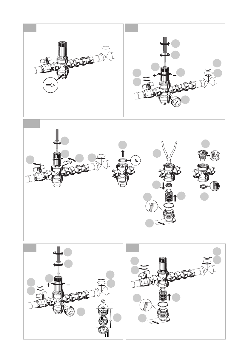
7.2 Assembly instructions
1. Thoroughly flush pipework
2. Install pressure reducing valve combination
o Note flow direction
o Install without tension or bending stresses
4. Technical data
Operating temperature max. 40°C (MTA06-B)
Minimum pressure drop 1 bar
Connection size
Honeywell GmbH 3 MU1H-1037GE23 R1208
max. 70°C (MTA06-H)
(WRAS for cold water use only)
3
/4" and 1"
Page 4

GB
8. Commissioning
8.1 Setting outlet pressure
Set outlet pressure min. 1 bar under inlet pressure.
1. Close shutoff valve on inlet
2. Release pressure on outlet side (e.g. through water tap)
3. Fit manometer
4. Close shutoff valve on outlet
5. Loosen slotted screw
o Do not remove slotted screw
6. Slacken tension in compression spring
o Turn control handle to the left (-) until it does not move
any more
7. Slowly open shutoff valve on inlet
8. Turn adjuster knob until the manometer shows the desired
value.
9. Retighten slotted screw
10.Slowly open shutoff valve on outlet
9. Maintenance
We recommend a planned maintenance contract with
an installation company
In accordance with DIN 1988, part 8, the following measures
must be taken:
9.1 Inspection
9.1.1 Pressure reducing valve
Interval: once a year
1. Close shut off valve on outlet
2. Check back pressure using a pressure meter when there
is zero through-flow
o If the pressure is increasing slowly, the valve may be
dirty or defective. In this instance, carry out servicing and
cleaning
3. Slowly open shutoff valve on outlet
9.1.2 Check valve
Interval: once a year
1. Close shut off valve on outlet
2. Open check valve
o Until the pressure is released, some water will flow out of
the check valve. After a short period of time the water
flow should stop. If the water continues to drip or run,
then the backflow preventer must be replaced - see
servicing of backflow preventer
3. Close check valve again
4. Open shut-off valve again
9.2 Maintenance
9.2.1 Pressure reducing valve
Frequency: every 1-3 years (depending on local
operating conditions)
To be carried out by an installation company
1. Close shutoff valve on inlet
2. Release pressure on outlet side (e.g. through water tap)
3. Close shutoff valve on outlet
4. Loosen slotted screw
o Do not remove slotted screw
Caution !
There is a spring in the spring bonnet. It may cause
injuries if the spring is derailing.
• Make sure tension in compression spring is slakkened!
5. Slacken tension in compression spring
o Turn control handle to the left (-) until it does not move
any more
6. Unscrew spring bonnet
o Use double ring wrench ZR06K
7. Remove slip ring
8. Remove valve insert with a pair of pliers
9. Unscrew filter bowl
o Use double ring wrench ZR06K
10.Remove slotted ring
11.Check that sealing ring, edge of nozzle and slotted ring are
in good condition, and if necessary replace the entire valve
insert
12.Remove filter, clean and reinsert
13.Place O-ring onto filter bowl
14.Reassemble in reverse order
Press in diaphragm with finger before inserting slip ring
Screw in filter cup hand-tight (without tools)
15.Adjust setting scale and set outlet pressure
9.2.2 Check valve
To be carried out by an installation company
1. Close shutoff valve on inlet
2. Release pressure on outlet side (e.g. through water tap)
3. Close shutoff valve on outlet
4. Replace check valve
MU1H-1037GE23 R1208 4 Honeywell GmbH
Page 5

GB
9.3 Adjusting the setting scale (MTA06-B only)
If the adjustment knob is removed, this setting is lost. A new
setting can be achieved using a pressure gauge.
1. Close shutoff valve on inlet
2. Release pressure on outlet side (e.g. through water tap)
3. Close shutoff valve on outlet
4. Fit manometer
5. Loosen slotted screw
o Do not remove slotted screw
6. Slowly open shutoff valve on inlet
7. Set desired outlet pressure (e.g. 4 bar)
8. Align scale (e.g. 4) in middle of viewing window
9. Retighten slotted screw
10.Slowly open shutoff valve on outlet
9.4 Cleaning
Caution !
Do not use any cleaning agents containing solvents
and/or alcohol to clean the plastic parts!
If necessary, the filter bowl and the filter can be cleaned.
To be carried out by an installation company or the
operator.
Detergents must not be allowed to enter the environment or the sewerage system!
1. Close shutoff valve on inlet
2. Release pressure on outlet side (e.g. through water tap)
3. Close shutoff valve on outlet
4. Unscrew filter bowl
o Use double ring wrench ZR06K
5. Remove filter, clean and reinsert
6. Place O-ring onto filter bowl
7. Screw in filter cup hand-tight (without tools)
8. Slowly open shutoff valve on inlet
9. Slowly open shutoff valve on outlet
10. Disposal
The pressure reducing valve comprises:
• Stainless steel
•Steel
• Plastic
Observe the local requirements regarding correct
waste recycling/disposal!
11. Troubleshooting
Problem Cause Remedy
Beating sounds Pressure reducing valve is too
large
Water is escaping from the spring
bonnet
Too little or no water pressure Shutoff valves up- or downstream of the
The outlet pressure set does not
remain constant
Check valve not sealing tightly in the
inlet side
Diaphragm in valve insert is faulty Replace valve insert
pressure reducing valve are not fully open
Pressure reducing valve is not set to the
desired outlet pressure
Filter in pressure reducing valve is contaminated
Pressure reducing valve is not fitted in flow
direction
Filter in pressure reducing valve is contaminated or worn
Valve insert, sealing ring or edge of nozzle
is contaminated or worn
Rising pressure on outlet (e.g. in boiler) Check check valve, safety group etc.
Pressure increases in the inlet side Replace check valve
Sealing surfaces soiled or worn Replace check valve
Call our Technical Customer Services
Open the shutoff valves fully
Set outlet pressure
Clean or replace filter
Fit pressure reducing valve in flow direction
(note direction of arrow on housing)
Clean or replace filter
Replace valve insert
Honeywell GmbH 5 MU1H-1037GE23 R1208
Page 6

GB
12. Spare Parts
Pressure Reducing Valve Combination MTA06-B High Pressure Reducing Valve Combination MTA06-H
1
5
2
4
2
3
No. Description Dimension Part No.
1 Spring bonnet
complete
2 Valve insert
complete
(without filter)
3 Shutoff valve
4 Union seal washer
(10 pcs.)
5 Blanking plug
with O-ring R
(5 pcs.)
6 Replacement filter
insert
7 O-ring set (10 pcs.)
8 Filter bowl with O-
ring
6
7
3
/4" 0901515
1" 0901517
3
/4" D06FA-1/2
1" D06FA-1B
3
/4" 2193100
1" 2193200
3
/4" 0901444
1" 0901445
1
/4"
3
/4" ES06F-1/2A
1" ES06F-1B
3
/4" 0901246
1" 0901499
3
/4" SK06ZH-1/2
1" SK06ZH-1
8
S06K-1/4
1
5
2
4
2
3
6
7
No. Description Dimension Part No.
9 Spring bonnet
complete
10 Valve insert
complete
(without filter) 1" D06FA-1A
11 Shutoff valve
12 Union seal washer
(10 pcs.) 1" 0901445
13 Blanking plug
with O-ring R
(5 pcs.)
14 Replacement filter
insert
15 O-ring
(10 pcs.) 1" 0901247
16 Brass filter bowl with
O-ring 1" SM06T-1A
3
1" 0900228
3
3
1" 2193200
3
1
/4"
3
1" ES06F-1A
3
3
8
/4" 0900227
/4" D06FA-1/2
/4" 2193100
/4" 0901444
S06K-1/4
/4" ES06F-1/2A
/4" 0901246
/4"SM06T-1/2
MU1H-1037GE23 R1208 6 Honeywell GmbH
Page 7

13. Accessories
6
4
8
2
r
ba
0
10
M07M
M07M Pressure gauge
Housing diameter 63 mm, rear connection thread
1
G
/4". Ranges: 0 - 4, 0 - 10, 0 - 16 or 0 - 25 bar.
Please indicate upper value of pressure range
when ordering
ZR06K Double ring wrench
For removal of spring bonnet and filter bowl
GB
ZR06K
Honeywell GmbH 7 MU1H-1037GE23 R1208
Page 8

Automation and Control Solutions
Honeywell GmbH
Hardhofweg
D-74821 Mosbach
Phone: (49) 6261 810
Fax: (49) 6261 81309
http://europe.hbc.honeywell.com
www.honeywell.com
Manufactured for and on behalf of the
Environmental and Combustion Controls Division of
Honeywell Technologies Sàrl, Rolle, Z.A. La Pièce
16, Switzerland by its Authorised Representative Honeywell GmbH
MU1H-1037GE23 R1208
Subject to change
© 2008 Honeywell GmbH
 Loading...