

Honeywell MT13-520 User Manual

L
8-Node
Multinode Module Service
MT13-520


L
Implementation
8-Node Micro TDC 3000
8-Node
Multinode Module Service
MT13-520
Release 500
CE Compliant
9/95

Copyright, Trademarks, and Notices
Printed in U.S.A. — © Copyright 1995 by Honeywell Inc.
Revision 01 -– September 15, 1995
While this information is presented in good faith and believed to be accurate,
Honeywell disclaims the implied warranties of merchantability and fitness for a
particular purpose and makes no express warranties except as may be stated in its
written agreement with and for its customer.
In no event is Honeywell liable to anyone for any indirect, special or consequential
damages. The information and specifications in this document are subject to
change without notice.

About This Publication
This publication provides instructions for use by the system service personnel, to service the
Multinode Module. It will help you determine how to perform service required on the module and to
identify spare parts. It also provides disassembly/assembly instructions useful when replacing the
required part.
This publication is to be used in conjunction with the remainder of the TDC 3000X bookset.
This publication supports TDC 3000X software release 500 and CE Compliant hardware.
Any equipment designated as “CE Compliant” complies with the European Union EMC and
Health and Safety Directives. All equipment shipping into European Union countries after
January 1, 1996 requires this type of compliance—denoted by the “CE Mark.”
Multinode Module Service 9/95
Standard Symbols
Scope
ATTENTION
CAUTION
WARNING
OR
53894
53893
The following defines standard symbols used in this publication
Notes inform the reader about information that is required, but not
immediately evident
Cautions tell the user that damage may occur to equipment if proper care is
not exercised
Warnings tell the reader that potential personal harm or serious economic
loss may happen if instructions are not followed
Ground connection to building safety ground
Ground stake for building safety ground
DANGER
SHOCK HAZARD
53895
DANGER
HIGH VOLTAGE
53896
53897
Electrical Shock Hazard—can be lethal
Electrical Shock Hazard—can be lethal
Rotating Fan—can cause personal injury
Multinode Module Service 9/95

Table of Contents
1 INTRODUCTION
1.1 Overview
1.2 Related Publications
2 MODULE DESCRIPTION
2.1 General Description
2.2 Module and Node Configurations
2.2.1 Multinode Module Node Configurations
2.2.2 Multinode Module Node Configurations (CE Compliant)
2.2.3 Multinode Module Board Types
2.2.4 Replacement Board Application Notes
2.3 Front Panel
2.4 Rear Panel
2. 5 Field Adjustment
3 TEST/TROUBLESHOOTING
3. 1 Tests
3. 2 Test Procedures
3.3 Troubleshooting
3.3.1 Power Supply/Fan
3.3.2 PWB Troubleshooting
3.3.2.1 Controller Boards
3. 3.2.2 Processor Board K2LCN
3.3.2.3 EPDG Board
4 DISASSEMBLY/ASSEMBLY
4.1 Disassembly
4.2 Assembly
5 SPARE PARTS
5. 1 Introduction
6 STARTUP
6.1 Visual Checks
6.2 Initialize Module
APPENDIX A—ALPHANUMERIC DISPLAYS
A. 1 Recommended Actions for Specific Code Occurrences
INDEX
Multinode Module Service i 9/95

Multinode Module Service ii 9/95
INTRODUCTION
Section 1
1.1 OVERVIEW
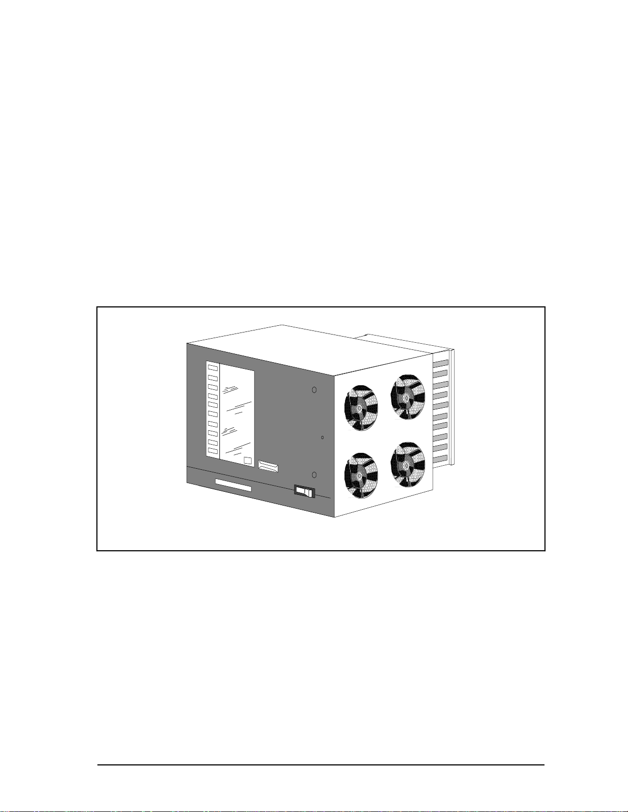
This manual provides detailed instructions for maintenance, test, troubleshooting, and
repair of the Multinode Module shown in Figure 1-1 (with front cover installed) and Figure
1-2. The Multinode Module will not have the front cover installed when mounting in
Micro TDC 3000 or LCN cabinets. The troubleshooting, disassembly, and assembly
procedures are effective down to the optimum replaceable-unit (ORU) level. An ORU parts
list is included and is keyed to a module-exploded view that is also used with the
disassembly and assembly procedures.
1
53679
Figure 1-1 — Multinode Module
Multinode Module Service 1-1 9/95
1.1
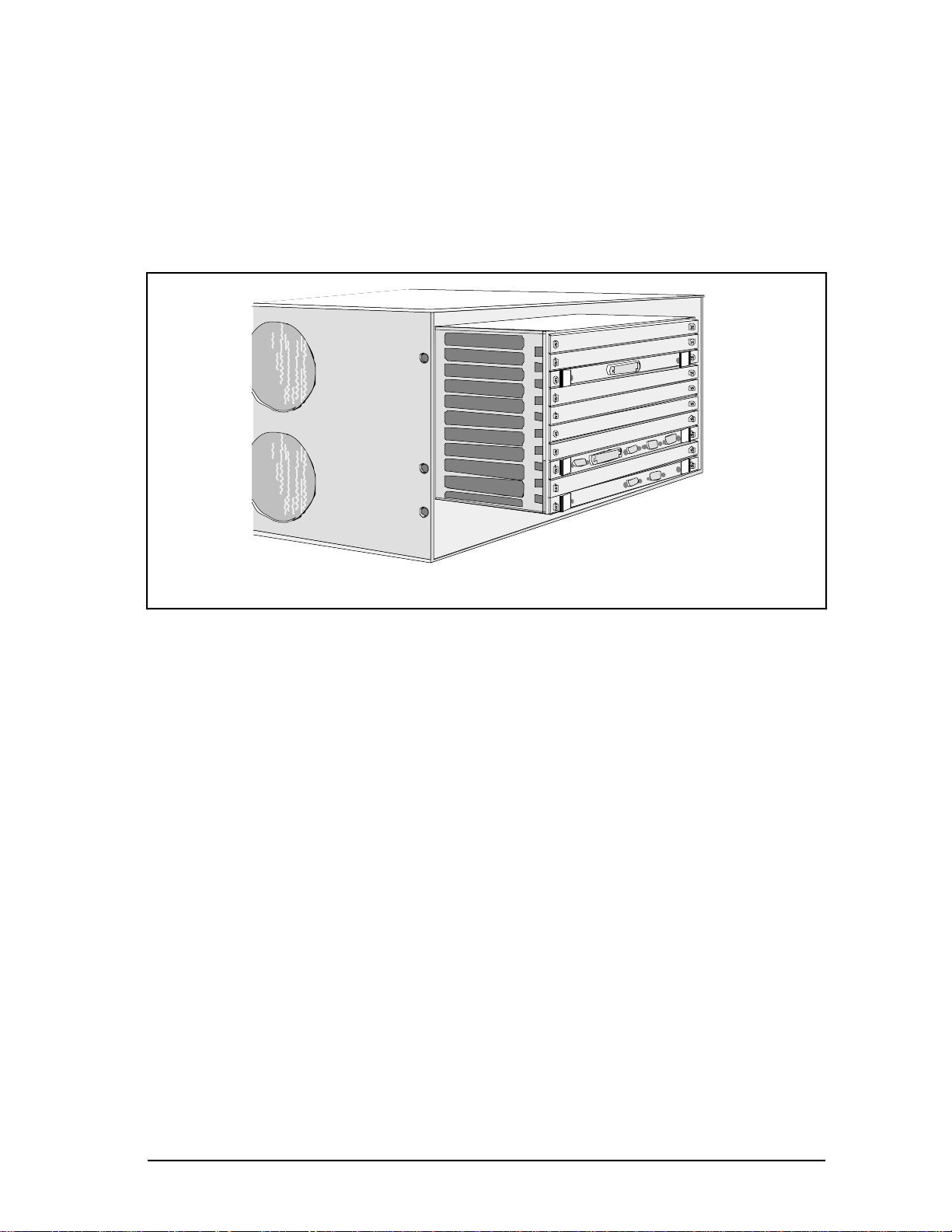
This manual also contains information about the EC compatible Ten-Slot Module. It
accommodates both the older and newer EC I/O board designs. The EC card file remains
the same in all other details except each I/O board has a faceplate which provides grounding
of the board and cable shield to the card file. The fan intake and exhaust openings on the
sides of the module are covered with a honeycomb wire mesh for EC Compliant protection.
The EC I/O card file is shown in Figure 1-2.
SPC-3 I/O
EPDGC I/O
TP-485-3 I/O
53898
Figure 1-2 — Multinode Module for EC
1.2 RELATED PUBLICATIONS
The following related publications should be referred to as required and available:
Publication
Title
Maintenance Test Operations
System Maintenance Guide
Test System Executive
Hardware Verification Test System
Core Module Test System
8-Node Enhanced Micrro TDC 3000
User’s Manual
Publication
Number
SW11-502 LCN Service - 1 3060-1
SW13-500 LCN Service - 1 3060-1
SW13-510 LCN Service - 3 3060-3
SW13-511 LCN Service - 3 3060-3
SW13-512 LCN Service - 3 3060-3
MT11-520 Implementation /
8-Node Micro
TDC 3000
Binder
Title
3091
Binder
Number
Multinode Module Service 1-2 9/95
MODULE DESCRIPTION
Section 2
2.1 GENERAL DESCRIPTION
The Multinode Module is designed to mount either horizontally in a standard NEMA rack
or vertically in a cabinet (or tower) designed to stand vertically on the floor. Cooling is
provided by four fans in one side of the module enclosure. An integral power supply is
located at the bottom (or side) of the module.
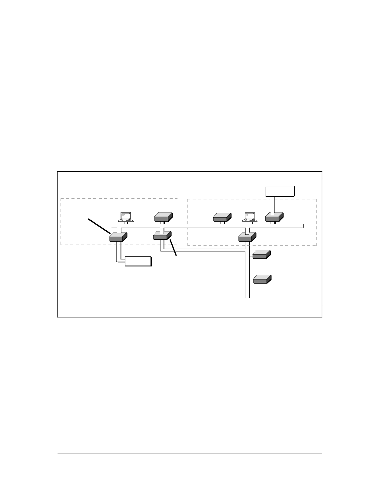
Each Multinode Module supports up to four functional nodes in the TDC 3000 System.
Each node occupies a specific address on the Local Control Network (LCN). Figure 2-1
illustrates a typical Micro TDC 3000 System using two Multinode Modules in vertical
cabinets.
(Example)
LEFT TOWER
Optional
Enhanced
Programmable
Logic Controller
Optional
Universal
i
RIGHT TOWER
History
Module
n
Application
Module
LCN
Universal
Station
DEC VAX
Optional
Computer
w
Network Interface
Module
2
620 LCS
(Example)
Optional Redundant
Network Interface
M
l
UNIVERSAL
CONTROL NETWORK
Figure 2-1 — Typical Micro TDC 3000 Multinode Module Application
Advanced Process
Manager
54120
Multinode Module Service 2-1 9/95

2.2
2.2 MODULE AND NODE CONFIGURATIONS
Circuit board slots are numbered from 1 to 10 starting at the bottom (nearest the power
supply). When the module is oriented vertically, the slots are numbered from right to left.
Nodes within a single Multinode Module are in a 3/3/2/2 arrangement, with slots 1 through
3 containing the first node, 4 through 6 containing the second node, slots 7 and 8
containing the third node, and slots 9 and 10 containing the fourth node.
The functional control boards are installed in the front card file of the module so that status
indicators on the boards may be viewed through the transparent cover. If an Input/Output
(I/O) adapter board (or paddleboard) is directly associated with a functional control board,
it is installed in the slot behind it in a card file at the rear of the module. Paddleboards
which do not perform an I/O function may also be installed in the rear card file in an unused
slot.
Multinode Module Service 2-2 9/95

2.2.1
2.2.1 Multinode Module Node Configurations
Because of the limited board space, the boards used to construct various nodes must
contain only certain boards and be configured as shown in Table 2-1.
CAUTION
Power must be removed from the module whenever you are removing or installing any board,
including an I/O paddleboard. Be sure that an I/O paddleboard is installed in the correct slot;
some boards have only one slot that they can be installed in without causing damage. I/O
paddleboards plugged into the wrong slot can cause traces on the backplane to burn open.
In the following table, slot numbers are identified by a-b-c. Remember, in the Multinode
Module 3/3/2/2 arrangement, slots are grouped by node, therefore, a given node may
occupy slots 1-2-3, 4-5-6, 7-8, or 9-10 to match slots a-b-c, or only a-b.
Table 2-1 — Node Configurations for Multinode Modules
Application Module (AM) Universal Station (US)
Slot Front Rear Slot Front Rear
c EPDG EPDG(P) I/O
b b Empty (3)
a K2LCN-4/8 (4) a K2LCN-4/6 (5) (1, 2)
Network Interface Module (NIM) History Module (HM)
Slot Front Rear Slot Front Rear
b EPNI NIM MODEM b SPC SPC I/O
a K2LCN-3 (1, 2) a K2LCN-3
Notes: (1) A TP485 I/O card is located in Slot 1 and 9 of the modules in the Micro TDC 3000.
(2) The TP485 in Slot 9 provides the interface to the twisted pair, short distance
(≤10 meters) TPLCN.
(3) The EPDG board set should be slots 3 and 6 with slots 2 and 5 empty.
(4) Standard AM is 4 Mw; optional is 8 Mw.
(5) Standard US is 4 Mw or 6Mw. 6MW is required for Universal Personality.
(Continued)
Multinode Module Service 2-3 9/95
2.2.1
CAUTION
Power must be removed from the module whenever you are removing or installing any board,
including an I/O paddleboard. Be sure that an I/O paddleboard is installed in the correct slot;
some boards have only one slot that they can be installed in without causing damage. I/O
paddleboards plugged into the wrong slot can cause traces on the backplane to burn open.
Note that a given node may occupy slots 1-2-3, 4-5-6, 7-8, or 9-10 to match slots a-b-c, or
only a-b.
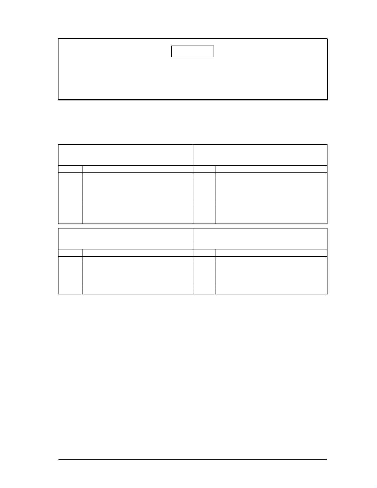
Table 2-1 — Node Configurations for Multinode Modules (Continued)
Computer Gateway (CG) PLC Gateway (PLCG)
Slot Front Rear Slot Front Rear
cc
b CLI CLI I/O b PLCI PLCI I/O
a K2LCN-2 a K2LCN-2
Redundant NIM Network Gateway (NG)
Slot Front Rear Slot Front Rear
b EPNI NIM MODEM b NGI NGIO
a K2LCN-3 (1, 2) a K2LCN-2
Notes: (1) A TP485 I/O card is located in Slot 1 and 9 of the modules in the Micro TDC 3000.
(2) The TP485 in Slot 9 provides the interface to the twisted pair, short distance
(≤10 meters) TPLCN.
Multinode Module Service 2-4 9/95
2.2.2
2.2.2 Multinode Module Node Configurations (CE Compliant)
Because of the limited board space, the boards used to construct various nodes must
contain only certain boards and be configured as shown in Table 2-1.
CAUTION
Power must be removed from the module whenever you are removing or installing any board,
including an I/O paddleboard. Be sure that an I/O paddleboard is installed in the correct slot;
some boards have only one slot that they can be installed in without causing damage. I/O
paddleboards plugged into the wrong slot can cause traces on the backplane to burn open.
In the following table, slot numbers are identified by a-b-c. Remember, in the Multinode
Module 3/3/2/2 arrangement, slots are grouped by node, therefore, a given node may
occupy slots 1-2-3, 4-5-6, 7-8, or 9-10 to match slots a-b-c, or only a-b.
Table 2-2 — Node Configurations for Multinode Modules (CE Compliant)
Application Module (AM) Universal Station (US)
Slot Front Rear Slot Front Rear
c EPDG2 EPDGC I/O
b b Empty (3)
a K2LCN-4/8 (4) a K2LCN-4/6 (5) (1, 2)
Network Interface Module (NIM) History Module (HM)
Slot Front Rear Slot Front Rear
b EPNI NIM MODEM b SPC SPC3 I/O
a K2LCN-3 (1, 2) a K2LCN-3
Notes: (1) A TP485 I/O card is located in Slot 1 and 9 of the modules in the Micro TDC 3000.
(2) The TP485 in Slot 9 provides the interface to the twisted pair, short distance
(≤10 meters) TPLCN.
(3) The EPDG2 board set should be slots 3 and 6 with slots 2 and 5 empty.
(4) Standard AM is 4 Mw; optional is 8 Mw.
(5) Standard US is 4 Mw or 6Mw. 6MW is required for Universal Personality.
(Continued)
Multinode Module Service 2-5 9/95

2.2.2
CAUTION
Power must be removed from the module whenever you are removing or installing any board,
including an I/O paddleboard. Be sure that an I/O paddleboard is installed in the correct slot;
some boards have only one slot that they can be installed in without causing damage. I/O
paddleboards plugged into the wrong slot can cause traces on the backplane to burn open.
Note that a given node may occupy slots 1-2-3, 4-5-6, 7-8, or 9-10 to match slots a-b-c, or
only a-b.
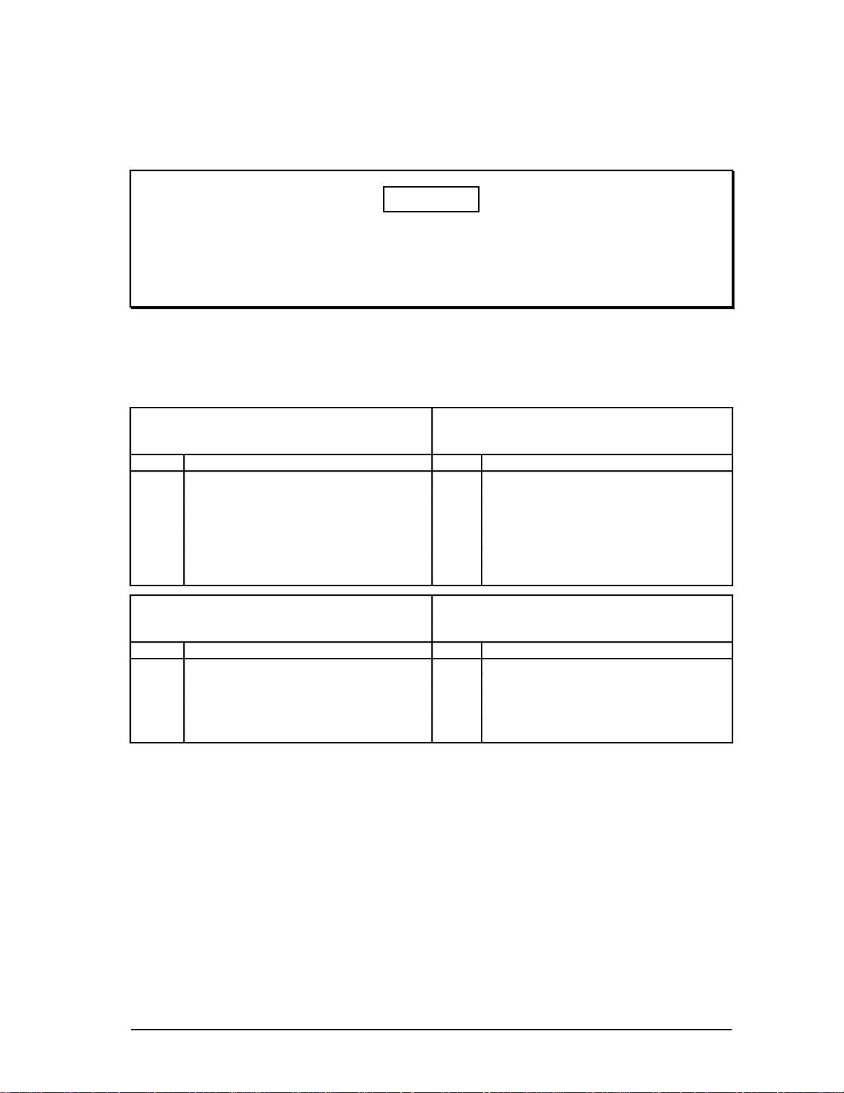
Table 2-2 — Node Configurations for Multinode Modules (CE Compliant) (Continued)
Computer Gateway (CG) PLC Gateway (PLCG)
Slot Front Rear Slot Front Rear
cc
b CLI CLI I/O b PLCI PLCI I/O
a K2LCN-2 a K2LCN-2
Redundant NIM Network Gateway (NG)
Slot Front Rear Slot Front Rear
b EPNI NIM MODEM b NGI NGFOM
a K2LCN-3 (1, 2) a K2LCN-2
Notes: (1) A TP485 I/O card is located in Slot 1 and 9 of the modules in the Micro TDC 3000.
(2) The TP485 in Slot 9 provides the interface to the twisted pair, short distance
(≤10 meters) TPLCN. The TP485 in Slot 1 provides the interface to the module
temperature sensors.
Multinode Module Service 2-6 9/95
 Loading...