

Page 1

X4 Series
Operating Instructions and
Maintenance Manual
Page 2

Alternative language versions are available for download from the Honeywell
Analytics website www.honeywellanalytics.com
Alternatieve talen versies zijn electronisch beschikbaar via onze web pagina van
Honeywell Analytics: www.honeywellanalytics.com
Les versions alternatives de langue sont disponibles pour le téléchargement du
website www.honeywellanalytics.com de Honeywell Analytics
Las versions alternativas de la lengua están disponibles para la transferencia
directa del website www.honeywellanalytics.com de Honeywell Analytics
Versioni in alter lingue, incluso l'italiano, sono disponibili e possono essere
scaricate dal sito web della Honeywell Analytics
www.honeywellanalytics.com
Zusätzliche Sprachen stehen zum Download auf folgender Webseite zur Verfügung. www.honeywellanalytics.com
X4 Series2
Page 3

Important Notice
System configurations of the detector are available with 4, 3, 2, and 1 gas sensor(s)
installed in order to provide specific protection for most major industrial applications
and compliance requirements. Though this operating manual is provided for the
detector with 4 gas sensors installed, the information in the manual also applies to
other system configurations of the detector with 3, 2, and 1 gas sensor(s) installed
as well (See Section 8 System Configurations Options).
To ensure proper functioning of this product, do not use it until you read and
completely understand this operating manual. It contains operating and maintenance
procedures to ensure proper detector function. For your safety, it is required to
calibrate the detector periodically (See Section 4 Calibration).
Honeywell Analytics can take no responsibility for use of its equipment if it is not
used in accordance with the instructions stated in the relevant manual. If further
details are required but not provided in this manual, contact Honeywell Analytics
or their agent.
Honeywell Analytics shall not be liable for any incidental or consequential damages
in connection with any modifications, errors or omissions in this manual.
While every effort has been made to ensure accuracy in this publication, no
responsibility can be accepted for errors or omissions. This publication is not intended
to form the basis of a contract, and the company reserves the right to amend the
design and specifications of the detectors without notice. Note too that data may
change as well as legislation, and you are advised to obtain copies of the most
recently issued regulations, standards and guidelines.
WARNINGS AND CAUTIONS
•
Substitution of any components may impair intrinsic safety.
Use only approved memory cards, part # 2566-0435, which are available
•
from Honeywell Analytics. Use of any other manufacturer or type will violate
intrinsic safety requirements.
Activation of the detector after the date on the packaging means less usable
•
life and shorter warranty period.
Use only approved ‘AA’ Alkaline Batteries, Energizer
•
only approved 'AA' NiMH recharchable cells. Quest 1500mAh, order part
number 2566-0454 (Quest part number HL-AAC1500). Use of any other
manufacturer or type will violate intrinsic safety requirements.
•
Use only two new batteries of the same type, when replacing the batteries.
•
The optional NiMH rechargeable batteries must be in fully charged condition
and replaced as a new pair. Do not attempt to charge the optional NiMH cells
in potentially hazardous areas
•
Replace batteries as soon as the detector emits a low battery alarm.
•
Battery life will be reduced at low temperatures.
•
Replace batteries only in an area known to be NON-HAZARDOUS.
•
Instrument contains no user serviceable parts. Contact Honeywell Analytics for any
servicing
X4 Series 3
requirements.
®
E91 or EN91: or use
(cont’d)
Page 4

Perform a Self-Test prior to each day’s use (See Section 3-1 Performing a
•
Self-Test).
Periodically test the sensors’ response to gas by exposing the monitor to a target gas
•
concentration that exceeds the alarm set points. Verify proper operation of audible,
visual and vibrating alarms during this test.
Use only factory supplied calibration gas for calibration. Accurate calibration
•
can be achieved only if specific concentrations of the correct gases are
used.
Calibration should be carried out in a well-ventilated area to avoid
•
contaminants.
Calibration cannot be carried out when the detector emits a low battery
•
alarm.
Do not use the detector in oxygen-enriched atmospheres.
•
The flammable sensor’s sensitivity can be adversely affected by exposure
•
to certain substances called “poisons”. Sulfur compounds, phosphorus
containing compounds, halogens, silicone or lead containing compounds
are examples of such poisons. Every effor t should be made to avoid
exposure to these substances. When the detector is exposed to such
substances, a gas test should be performed on the flammable sensor
to verify its accuracy and a calibration performed if necessary.
Extended exposure of the detector to certain high concentrations of flammable
•
gases and air may stress the flammable detector element, which can
seriously affect its performance. If an alarm occurs due to high concentration
of flammable gases, recalibration should be performed, or if needed, the
sensor replaced.
Do not use solvents, soap, polishes or any product containing silicon
•
compounds to clean the detector as these can cause damage to the
sensors.
•
Do not expose the detector to electrical shock and/or severe mechanical
shock. When the detector is exposed to such shocks, a check should be
performed on the sensors to verify its accuracy and a calibration performed
if necessary.
•
Disabling one or more installed sensors configures the detector to a 1, 2,
or 3-gas unit. No protection is provided for the gas targeted by the disabled
sensor(s).
Do not install or remove the memory card in the detector or attempt to read,
•
download or write to the memory card using a memory card reader and/or
computer in potentially hazardous atmospheres.
Do not remove the batteries from the detector while the power is on. This can
•
cause fatal damage to the optional memory card if installed.
No gas will be detected while in the set-up mode or the gas exposure status
•
review mode.
The desktop USB memory card reader and data logging kit are not
•
certified intrinsically safe and must not be used in potentially hazardous
atmospheres.
X4 Series4
Page 5

Contacting Honeywell Analytics Customer Business Centers
Americas (Minimax4 series) Europe and ROW (ImpulseX4 series)
400 Sawgrass Corporate Parkway Wilstrasse 11-U11
Suite 100 Ch-8610 Uster
Sunrise, Florida 33325 Switzerland
Tel: +1 954 514 2700 Tel: +41 (0)1 943 4300
Toll free: +1 800 538 0363
Fax: +1 954 514 2784 Fax: +41 (0) 1 943 4398
sales@honeywellanalytics.com sales@honeywellanalytics.co.uk
Or visit our web site at www.honeywellanalytics.com
X4 Series 5
Page 6

Additional Warnings and Cautions for Canadian Certification
and Other Global Certification Bodies
WARNING
Substitution of any components may impair intrinsic safety.
AVERTISSEMENT
La substitution de composants peut compromettre la sécurité intrinsèque.
CAUTION
For safety reasons this equipment must be operated and serviced by qualified
personnel
operating or servicing.
Pour des raisons de sécurité, cet équipement doit être utilisé, entretenu et réparé
uniquement par un personnel qualifié. Étudier le manuel d’instructions en
entier avant d’utiliser, ’entretenir ou de réparer l’équipement.
High off-scale reading may indicate explosive concentration.
Des lectures supérieures à l’échellepeuvent indiquer des concentrations
explosives.
only. Read and understand instruction manual completely before
ATTENTION
CAUTION
ATTENTION
CAUTION
Before each day’s usage sensitivity must be tested on a known concentration of
methane equivalent to 25-50%LEL. Accuracy must be within +/-20% of actual
concentration. Accuracy may be corrected by performing proper calibration on
the detector.
ATTENTION
Chaque jour, avant toute utilisation, tester la sensibilité sur une concentration
connue de méthane équivalente à 25-50% LEL. La précision doit être comprise
dans une plage de +/-20% de concentration réelle. A précision peut être
corrigée en effectuant un étalonnage approprié du détecteur.
X4 Series6
Page 7

WARNING
Under proper calibration procedures, repetitive calibration failures could indicate
that the sensor is either approaching its end of life, or it has been seriously
contaminated, or both.
AVERTISSEMENT
Si Les Procédures D’étalonnage Sont Bien Respectées, Des Défauts D’étalonnage
Répétitifs Peuvent Indiquer Que Le Capteur Arrive En Fin De Vie Ou Qu’il A
Été Sérieusement Contaminé, Ou Les Deux.
WARNING
The detector must not be removed from its rubber boot during transportation or
use, and if the rubber boot is removed for servicing or any other reason, it must
be replaced before the instrument is placed back in service.
AVERTISSEMENT
Le support en caoutchouc du détecteur ne doit jamais être retiré pendant
son utilisation ou son transport. Si pour un quelconque motif, d’entretien ou
autre, cette protection a été retirée, elle doit toujours être remise en place avant
d’utiliser l’instrument.
Only the combustible gas detection portion of this instrument has been assessed
for performance.
S e u l l e f o n c t i o n n e m e n t d e la p a r t i e d é t e c t i o n d e g a z
combustible de cet instrument a été évalué
The csa symbol, “exia”, represents intrinsically safe, or in french, sécurité
intrinsèque.
Le symbole csa “exia” signifie “sécurité intrinsèque”
WARNING
Use only the approved Honeywell Analytics charger (part number 2566-0484)
when charging the sealed rechargeable battery pack (part number 2566-0482 for
Minimax4 series and part number 2566-0462 for Impulse X4 series). Use of any
other charger will void the intrinsic safety certification of the instrument.
AVERTISSEMENT
Utiliser uniquement le chargeur Honeywell Analytics homologué (référence 2566-
0484) lors de la mise en charge du kit batterie étanche rechargeable (référence
2566-0482 pour la série Minimax4 et référence 2566-0462 pour la série Impulse X4).
En cas d’utilisation de tout autre chargeur, la certification de sécurité intrinsèque de
l’instrument sera nulle et non avenue.
X4 Series 7
Page 8

WARNING
Use only the Honeywell Analytics supplied ac adapter (part number 2566-0483)
to connect to the cradle charger (part number 2566-0484).
AVERTISSEMENT
Utiliser uniquement l’adaptateur à courant alternatif Honeywell Analytics
fourni (référence 2566-0483) pour
(référence 2566-0484).
connecter l’instrument au chargeur socle
WARNING
The charger units contain no user serviceable parts. No attempt should be
made to alter or repair the charger.
AVERTISSEMENT
Les chargeurs ne comportent pas de pièces d’entretien sur lesquelles
l’utilisateur peut intervenir. Ne pas essayer de modifier ni de réparer le
chargeur.
X4 Series8
Page 9

Table of Contents
1. Introduction .......................................................................11
1-1. Product Overview ...................................................11
1-2. Basic Button Operation ..........................................12
1-3. LCD Display .............................................................12
1-4. Standard Accessories ............................................13
2. Turning the Detector On and Off ......................................13
2-1. Turning the Detector On .........................................13
2-1-1. Displaying the Firmware Version
2-1-2. Clearing the STEL and TWA Values
2-1-3. Checking the Memory Card
2-1-4. Power-Up Self-Test
.........................................15
2-1-5. Checking the Calibration Due Date
....................13
...............14
............................14
................15
2-2. Turning the Detector Off .........................................15
3. Operation ...........................................................................16
3-1. Performing a Self-Test ............................................16
3-2. Measuring Mode......................................................17
3-2-1. Flipping the Display
........................................18
3-3. Testing Sensors and Alarms (Bump Testing) .......18
3-4. Gas Alarms ..............................................................18
3-4-1. Gas Alarms for the Minimax4 series
3-4-2. Gas Alarms for the ImpulseX4 series
...............19
.............19
3-5. Gas Exposure Status Review ................................21
3-6. Confidence Flash/Beep ..........................................22
3-7. Low Battery .............................................................22
3-8. Data Logging ...........................................................22
4. Calibration..........................................................................24
4-1. Calibration Prompt ..................................................24
4-2. Zero Calibration (Span Calibration for Oxygen) ..24
4-3. Span Calibration (for Flammable and Toxic
Sensors Only) ..........................................................25
4-3-1. Pass Code Input
4-3-2. Span Gas Information
4-3-3. Span Gas Setting
4-3-4. Gas Search and Countdown
4-3-5. Span Calibration Result
.............................................26
.....................................26
...........................................27
..........................27
..................................28
5. Set-Up Mode ......................................................................29
5-1. Entering the Set-Up Mode ......................................30
5-2. Changing the Detector Set-Up ...............................31
5-3. Exiting the Set-Up Mode.........................................31
X4 Series 9
Page 10

6. Maintenance.......................................................................32
6-1. Replacing the Batteries ..........................................32
6-2. Installing or Removing the Memory Card .............33
6-4. Replacing the Expired Sensor ...............................34
7. Optional Accessories........................................................35
8. System Configuration Options ........................................36
8-1. System Configurations for the Minimax4 series ..36
8-2. System Configurations for the ImpulseX4 series 36
Appendix A ............................................................................37
A-1. Calibration Mode Menu Structure 1/2 ...................37
A-2. Calibration Mode Menu Structure 2/2 ...................38
A-3. Set-up Mode Menu Structure 1/4 ..........................39
A-4. Set-up Mode Menu Structure 2/4 ..........................40
A-5. Set-up Mode Menu Structure 3/4 ..........................41
A-6. Set-up Mode Menu Structure 4/4 ..........................42
Appendix B ............................................................................43
B-1. Sensor Cross-Sensitivity .......................................43
B-1-1. H2S and CO SureCell Cross-Sensitivity .........43
B-1-2. O
B-1-3. Flammable Cross-Sensitivity
Cross-Sensitivity .......................................43
2
..........................44
B-2. Flammable Lower Explosive Limit ........................45
Appendix C ............................................................................46
C-1. Warranty ..................................................................46
C-2. Accuracy Statement ...............................................47
C-3. Declaration ..............................................................48
C-3-1. Declaration for the Minimax4 series
C-3-2. Declaration for the ImpulseX4 series
...............48
.............49
Appendix D ............................................................................50
D-1. Specifications .........................................................50
D-1-1. Specifications for the Minimax4 series ...........50
D-1-2. Specifications for the ImpulseX4 series
.........51
X4 Series10
Page 11

1. Introduction
Visual Alarm
Sensor Grille
Audible Alarm
LCD Display
Locking Tab
Crocodile Clip
Battery Holder
UP Button
DOWN Button
ON/OFF Button
Threaded Hole for
Flow Adaptor
Left
Right
Front
Bottom
The X4 series is an easy to use personal gas detector, designed for monitoring
the atmosphere for potentially hazardous levels of flammables, oxygen, carbon
monoxide, and hydrogen sulfide. It uses a front-mounted LCD display to show
readings of the gases being measured and other useful information. A loud audible
alarm and bright visual alarm are used to warn users when the concentrations of
measured gases exceed the alarm set points. It has built-in cell decay compensation,
thermal shock protection, and Reflex™, a patented cell check technique, for
maximum reliability.
1-1. Product Overview
X4 Series 11
Page 12
1
2 3 4
5 6
7
8
9
10
11
1213
14
15
16
17
1-2. Basic Button Operation
ON/OFF button
Turn on the detector
•
Turn off the detector
•
Self-Test
•
ZERO calibration
•
SPAN calibration
•
Accept a user set-up change
•
Latched Alarm acknowledgement
•
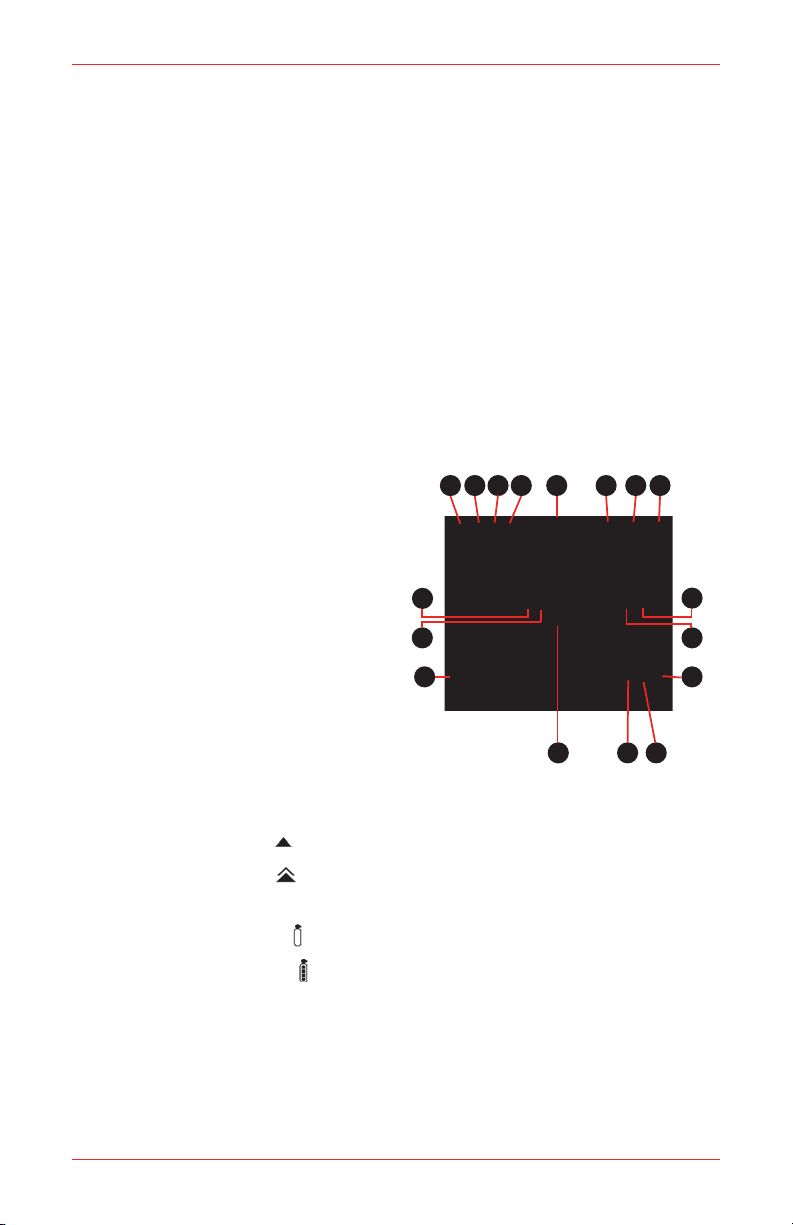
1-3. LCD Display
Test Pass Icon
1.
Test Fail Icon
2.
High Peak Icon
3.
Low Peak Icon (for O2 only)
4.
Alarm Icon
5.
Data Logging Icon
6.
Battery Icon
7.
Pass Code Protection Icon
8.
%Vol Unit Icon
9.
%LEL Unit Icon
10.
STEL Icon
11.
TWA Icon
12.
Alarm Level 1 Icon
13.
Alarm Level 2 Icon
(for flammable and toxic)
Zero Calibration Icon
14.
Span Calibration Icon
Gas Label Icon
15.
O2 Deficiency Alarm Icon
16.
O2 Excess Alarm Icon
17.
UP button
Scroll through status or menu
•
options
Increase value
•
Ac t i v a t e / d ea c t i v a t e fl i p p e d
•
display
Activate backlight
•
DOWN button
Scroll through status or menu
•
options
Decrease value
•
Activate backlight
•
The LCD display has a backlight that
will operate automatically whenever
an alarm occurs, and also whenever
any button is pressed. To turn on the
backlight while staying in the measuring
mode in a low light area, press the UP
or DOWN button once.
X4 Series12
Page 13

1-4. Standard Accessories
The items listed below are included with the X4 series. For damaged or missing
parts, contact Honeywell Analytics or their agent.
Part No. Description Qty
2566-0424 Calibration Certicate 1
2566-0422 Quick Start Guide 1
2566-0433 Alkaline Batteries (1.5V AA), Energizer® E91 or EN91 2
2566-0426N Flow Adaptor (Neotronics) 1
2566-0426L Flow Adaptor (Lumidor) 1
2566-0480 Protective Rubber Boot (Neotronics) 1
2566-0445 Protective Rubber Boot (Lumidor) 1
2566-0443 Tubing (45 cm/18”) 1
2566K0130 Crocodile Clip Kit 1
2566-0420 Manual 1
2. Turning the Detector On and Off
Before turning the detector on for the first time, you will need to install two “AA”
alkaline (Energizer® E91 or EN91) batteries (See Section 6-1 Replacing the
Batteries).
A sealed rechargeable battery pack (part number 2566-0482 for the Minimax,
and 2566-0462 for the Impulse) is also available (See Section 7 Optional
Accessories)
If you plan on logging data and have a memory card, now is also a good time to
install the card (See Section 6-2 Installing or Removing the Memory Card).
2-1. Turning the Detector On
Press and hold the ON/OFF button for 2 seconds and the detector will turn on.
2-1-1. Displaying the Firmware Version
The detector will display the version of the firmware.
X4 Series 13
Page 14

2-1-2. Clearing the STEL and TWA Values
When the non-zero STEL and/or TWA values are carried over from the previous
measurement, a “Delete no” prompt will be displayed with the gas labels and the STEL
and TWA icons. (When the STEL and TWA values are zero, the “Delete no” prompt
will not be displayed.)
Press the UP or DOWN buttons to scroll
to “no” or “YES” and press the ON/OFF
button to select.
or
When “no” is selected, the recorded STEL and TWA values will be used as initial
STEL and TWA values for the current session. When “YES” is selected, the STEL
and TWA values will be cleared.
2-1-3. CHECKING THE MEMORY CARD
The detector will check the memory card in the memory card slot. When a properly
formatted FAT16 memory card with a data full condition is detected, a “Data Fu” message
will be displayed followed by a “Delete no” prompt. (When a properly formatted FAT16
memory card is not full of data, the “Data Fu” message and the “Delete no” prompt will
not be displayed).
Press the UP or DOWN buttons to scroll to “no” or “YES” and press the ON/OFF
button to select.
or
X4 Series14
Page 15

When “no” is selected, the detector keeps the current data file and the Data Logging
icon will not be displayed in the measuring mode which indicates that no data is
being logged. When “Yes” is selected, the detector deletes the current data file and
creates a new file for data logging. The Data Logging icon will be displayed in the
measuring mode which indicates that data is being logged.
The detector does not support either FAT32 or NTFS format for the memory card.
When a memory card with non-FAT16 format is detected, a “Card Er” message will
be displayed with a single beep. (When a properly formatted FAT16 memory card
is detected, a “Card Er” message will not be displayed.)
The Data Logging icon will not be displayed in the measuring
mode which indicates that no data is being logged.
2-1-4. Power-Up Self-Test
The detector will beep and perform a power-up Self-Test. If the detector passes
the Self-Test, the Test Pass icon is displayed. If the Test Fail icon is displayed
and the Test Pass icon blinks with 1 beep and 1 flash every 5 seconds, then the
detector has failed the Self-Test (See Section 3-1 Performing a Self-Test).
2-1-5. Checking the Calibration Due Date
The detector checks the calibration due date stored in the detector after the Power-Up
Self-Test. When the number of days remaining until calibration is due reaches zero,
a "CAL dUE dAY 0" message will be displayed to remind the user that a calibration
needs to be performed.
To perform the calibration, see Section 4 Calibration.
2-2. Turning the Detector Off
To turn off the detector, press and hold the ON/OFF button while in the measuring mode.
A countdown will be displayed for 5 seconds, and then the detector will beep and
turn off.
X4 Series 15
Page 16

3. Operation
3-1. Performing a Self-Test
When the ON/OFF button is pressed, the detector checks the sensor, circuit, batteries,
and audible, visual, and vibrating alarms.
The detector will do the following:
= Turn on all the display elements
= Test the audible, visual, and vibrating alarms
= Check the battery, electronic circuit and sensors
a a
Display the level 1 (flammable and toxic low, O2 excess) and level 2 (flammable
•
and toxic high, O2 deficiency) alarm set points
Display the STEL and TWA alarm set points (for CO & H2S only).
•
a a a
Level 1 Level 2 STEL
TWA
*Examples shown for default settings of each gas for the Minimax4 series.
X4 Series16
Page 17

Display the result of the Self-Test as follows:
•
Test Pass Test Fail
Self-Test
Result
Pass None None
Fail
Additionally, the detector will periodically check its batteries, electronic circuit and
sensors.
If it passes, the Test Pass icon will be displayed. If it fails, the Test Fail icon
will be displayed and the Test Pass icon will blink with 1 beep and 1 flash every
5 seconds.
Note
If the Self-Test has failed, repeat the Self-Test. If a second failure occurs, contact
Honeywell Analytics or their agent
Display Audible Alarm Visual Alarm
1 beep every 5
sec
1 flash every 5
sec
3-2. Measuring Mode
The detector may be used as either a “diffusion” or “sample-draw” type monitoring
device. In normal operation, the detector is worn on the belt or held by hand. Once
turned on, the detector monitors continuously. The atmosphere being measured
reaches the sensor by diffusion through the vents of the grille cover. Normal air
movements are enough to carry the sample to the sensors, which react to the
concentrations of the gases being measured. This type of “diffusion” operation
monitors only the atmosphere that immediately surrounds the detector. It is possible
to use the detector to sample locations that are remote from the detector by using
a flow adaptor and an optional hand aspirator. When using the flow adaptor, ensure
that the sample flow direction matches the arrow mark.
The gas types and concentration values for each sensor are displayed. If fewer than
four sensors are installed, the unused sensor position(s) will be blank.
Normal Display
X4 Series 17
Page 18

3-2-1. Flipping the Display
The LCD display can be flipped upside down by pressing and holding the UP button
for 2 seconds. This allows easy reading when the detector is clipped to a waist belt
or chest pocket.
Flipped Display
3-3. Testing Sensors and Alarms (Bump Testing)
To maintain optimal accuracy, the detector should be periodically supplied with
a known concentration test gas (bump test) and if the readings are outside of
15% of the applied gas concentration, a span calibration should be performed,
under conditions of standard temperature (15°C to 25°C), humidity and pressure.
Follow local regulations and/or your company’s policy on the frequency of bump
testing. For more information on test gas, contact your local Honeywell Analytics
representative.
3-4. Gas Alarms
The detector has two levels of instantaneous gas alarms, of which the level 2
(flammable and toxic high, O2 deficiency) alarm is more urgent than the level 1
(flammable and toxic low, O2 excess) alarm for flammable and toxic. The O2 excess
and deficiency alarms are equally important. It also has a 15-minute STEL alarm
and an 8-hour TWA alarm for the carbon monoxide and hydrogen sulfide sensors.
Note
STEL (Short Term Exposure Limit) and TWA (Time-Weighted Average)
comply with relevant agency standards.
TWA is an 8-hour time-weighted average, so if the work shift exceeds 8 hours,
the readings will still be logged but averaged over the 8-hour period.
The user can set up the level 1 alarm point, level 2 alarm point, STEL alarm point,
TWA alarm point and alarm latch mode in the set-up mode. (See Section 5 Set-Up
Mode).
X4 Series18
Page 19

3-4-1. Gas Alarms for the Minimax4 series
The Minimax4 series is supplied with the following alarm increments, alarm ranges,
and default alarm set points:
Level 1 (Flammable
All
or
and Toxic Low, O2
Excess) Alarm
21.5~30%
Vol
2~60%
LEL
or
0.10~ 3%
Vol
5-999
ppm
3-250
ppm
Alarms
Gas Type Increment Range Default Range Default Range Default Range Default
Oxygen (O2) 0.1% Vol
Flammable
(Exp)
Carbon
Monoxide
(CO)
Hydrogen
Sulde (H2S)
1% LEL
0.01% Vol
1 ppm
1 ppm
23.5%
Vol
10%
LEL
or
0.50%
Vol
35 ppm
10 ppm
Level 2 (Flammable
and Toxic High, O2
Deciency) Alarm
1-20.5%
2~60%
0.10~3%
5~999
3~250
Vol
LEL
Vol
ppm
ppm
19.5%
Vol
20%
LEL
or
or
1%
Vol
100 ppm
15 ppm
STEL Alarm TWA Alarm
N/A N/A N/A N/A
N/A N/A N/A N/A
5~999
ppm
3~250
ppm
100 ppm
15 ppm
5~999
ppm
3~250
ppm
35 ppm
10 ppm
3-4-2. Gas Alarms for the ImpulseX4 series
The ImpulseX4 series is supplied with the following alarm increments, alarm ranges,
and default alarm set points:
Level 1 (Flammable and
All
or
Toxic Low, O2 Excess)
Alarm
21.5~30%
2~60% LEL
0.10~ 2.64%
23% Vol 1-20.5% Vol 19% Vol N/A N/A N/A N/A
Vol
or
Vol
0.44%
Alarms
Gas Type Increment Range Default Range Default Range Default Range Default
Oxygen (O2) 0.1% Vol
Flammable
(Exp)
Carbon
Monoxide
(CO)
Hydrogen
Sulde (H2S)
1% LEL
0.01% Vol
1 ppm 5-999 ppm 35 ppm 5~999 ppm 400 ppm
1 ppm 3-250 ppm 10 ppm 3~250 ppm 40 ppm
10%
LEL
or
Vol
Level 2 (Flammable
and Toxic High, O2
Deciency) Alarm
2~60% LEL
or
0.10~2.64%
Vol
20%
LEL
or
0.88%
Vol
STEL Alarm TWA Alarm
N/A N/A N/A N/A
5~999
ppm
3~250
ppm
200 ppm
10 ppm
5~999
ppm
3~250
ppm
30 ppm
5 ppm
Note
For flammable, carbon monoxide, and hydrogen sulfide, level 1 alarm can
only be set to less than or equal to the level 2 alarm. When level 1 and
level 2 alarms are set to the same value, the level 2 alarm action overrides
the level 1 alarm.
The maximum value of the level 2 alarm in %Vol for flammable gas varies
depending on the gas. (See Appendix B-2 Flammable Lower Explosive
Limit.)
X4 Series 19
Page 20

If an alarm occurs, the icons blink and relevant alarm level icons, s (Level 1 for
flammable and toxic, and O2 excess), (Level 2 for flammable and toxic), t (O2 deficiency),
(STEL), or (TWA) will be displayed according to the alarm level for the gas
type in question.
Alarm Type Display* Audible Alarm Visual Alarm Vibrating Alarm
Level 1 Alarm
Level 2 Alarm
STEL Alarm
TWA Alarm
3 Tones/ 2 Beeps
per 1 second
5 Tones/ 4 Beeps
per 1 second
5 Tones/ 4 Beeps
per 1 second
5 Tones/ 4 Beeps
per 1 second
2 Flashes
per 1 second
4 Flashes
per 1 second
4 Flashes
per 1 second
4 Flashes
per 1 second
once every 2
seconds
once every 1
second
once every 1
second
once every 1
second
* Examples shown for default settings of each gas for the Minimax4 series.
Note
In latching alarm mode, once an alarm occurs, the audible, visual and
vibrating alarms continue to operate even after the atmospheric hazard
has cleared. By pressing the ON/OFF button, the alarm will be cleared
(after the atmospheric hazard has cleared). Any subsequent alarm will
reactivate the audible, visual and vibrating alarms.
In non-latching alarm mode, should the gas alarm occur the detector
would enter alarm condition. When the reading returns to a normal level,
the audible, visual and vibrating alarms will stop.
If the measured reading exceeds the range of the sensor, the full-scale
value will blink.
See Section 5 Set-up Mode for more information on Latching/NonLatching Alarms
X4 Series20
Page 21

3-5. Gas Exposure Status Review
CAUTION
No gas will be detected while in the gas exposure status review mode.
The detector records the maximum readings, minimum readings (for oxygen only),
STEL and TWA values (for toxic only). While in measuring mode, these can be viewed
by pressing the UP or DOWN button. The first press of the UP or DOWN button turns on
the backlight if it is not already on. The exposure status can be scrolled through in the
order of High Peak ( ), Low Peak ( ), STEL ( ), and TWA ( ), followed by Calibration
Due Date, Current Date, and Current Time by pressing the UP button or in reverse order
by pressing the DOWN button.
Note
If no button is pressed within 10 seconds, the detector will revert back to
the measuring mode.
Gas Exposure
Status
High Peak
Low Peak
STEL
TWA
Calibration Due
Date
Current Date
Display Description
Maximum gas exposure levels encountered during work shift.
Note: To clear the high peak values, press the ON/OFF button
while the values are
displayed.
Minimum oxygen level encountered during work shift.
Note: To clear the low peak value, press the ON/OFF button while
the value is displayed.
Short-term exposure limit based on a 15-minute period. Note:
The STEL value can be cleared manually when the power is
turned on or will be cleared automatically if the power is kept
turned off for more than 15 minutes.
Time-weighted average based on an 8-hour workday. Note: The
TWA value can be cleared manually when the power is turned on
or will be cleared automatically if the power is kept turned off for
more than 8 hours.
Remaining days until next SPAN calibration
Current date in MM DD - YY format (US) or DD MM - YY format
(EU)
Current Time
Current time in HH:MM:SS format (24 hour format)
* Examples shown for the status review for the Minimax4 series
X4 Series 21
Page 22

3-6. Confidence Flash/Beep
If selected, the detector will emit a flash and a beep once every 30 seconds to indicate that
the detector is operating. The user can select whether this feature is activated or
not, and whether it is an audible signal, visual signal or both (See Section 5 SetUp Mode). If any error or fault is detected, the confidence flash/beep will stop. The
factory default is no confidence flash/beep.
3-7. Low Battery
When the detector’s battery level reaches a preset level, it will warn the user that the battery
is low and needs replacing by generating a beep and flashing the alarm LED once
every 5 seconds. Also, the Test Fail icon will be displayed and the Low Battery icon
and Test Pass icon will blink alternately. When the battery is finally exhausted,
the Test Fail icon and Low Battery icon will blink simultaneously with seven
beeps and “bAttEry oFF” will be displayed. Pressing the ON/OFF button will turn
the detector off completely.
After a low battery alarm, the batteries should be replaced as shown in Section 6-1
Replacing the Batteries.
3-8. Data Logging
WARNING
Do not install or remove the memory card in the detector or attempt to read,
download or write to the memory card using a memory card reader and/or
computer in potentially hazardous atmospheres.
Do not remove the batteries from the detector while the power is on. This can
cause fatal damage to the optional memory card if installed.
Before you can begin data logging, you will need to purchase a memory card and a card
reader. You will also need PC software, which you can either download from our web site
(www.honeywellanalytics.com), or you can purchase it on CD. (See Section 7
Optional Accessories.)
WARNING
Use only approved memory cards, part # 2566-0435, which are available
from Honeywell Analytics. Use of any other manufacturer or type will
violate intrinsic safety requirements.
Do not use a memory card containing non-X4 data. The detector or card
reader will either erase non-X4 data or reformat the memory card.
Memory card readers can be purchased from Honeywell Analytics or from a
local source of your choice. Card Readers must be able to read both MMC
(MultiMediaCard) and SD (SecureDigital) cards.
When the detector is turned on, it will check the memory card in the memory card slot
if card is installed. When a properly formatted blank memory card is detected, the Data
Logging icon will be displayed in the measuring mode which indicates that data
is being logged.
X4 Series22
Page 23

Note
The detector only supports FAT16 format for the memory card.
The detector will start data logging automatically and save
the gas readings at a user-configurable interval. The factory
default interval is 60 seconds. (See Section 5 Set-Up
Mode.)
Note
Should an alarm be activated while in the data logging mode, varied alarm
sound may be generated, as the detector periodically writes data to the
memory card.
W h e n t h e m e m o r y c a r d b e c o me s fu l l i n th e me a s u r i n g m o d e ,
the detector will stop data logging and the Data Logging icon will blink which
indicates that no data is being logged.
Note
The detector cannot format the memory card.
WARNING
The detector ignores the write-protect feature of the SD memory card.
When the Data Logging icon is either blinking or not displayed, it
indicates that no data is being logged.
To install or remove the memory card, see Section 6-2 Installing or Removing the
Memory Card.
X4 Series 23
Page 24

4. Calibration
Note
Calibration should be carried out with fresh batteries.
WARNING
Calibration cannot be carried out when the detector emits a low battery
alarm.
The calibration mode menu structure is shown in Appendix A (A-1 and A-2).
4-1. Calibration Prompt
To enter calibration mode while in measuring mode, press the ON/OFF button 2
times.
A “CAL no” prompt will be displayed.
Press the UP or DOWN buttons to alternate between “no”
or “YES” and press the ON/OFF button to select.
or
When “no” is selected, the calibration will be aborted. When “YES” is selected, the
calibration will be performed.
4-2. Zero Calibration (Span Calibration for Oxygen)
ZERO calibration must be performed in a clean atmosphere. It is recommended that
a ZERO calibration be performed daily or after any gas alarm.
The detector will initiate a ZERO calibration showing a blinking ZERO
•
Calibration icon and a countdown from ‘020’ to ‘000’.
a
Countdown
When the ZERO calibration has been completed successfully for all sensors,
•
the Test Pass icon will blink for 5 seconds.
X4 Series24
Page 25

If the ZERO calibration fails for one or more sensors, the detector will give a
•
single beep and a single flash and both the Test Pass icon and Test Fail
icon will blink for 5 seconds.
If the ZERO calibration fails for all sensors, the detector will give a single beep
•
and a single flash and only the Test Fail icon will blink for 5 seconds.
All Pass Some Pass/Fail All Fail
Note
If any sensor has failed, repeat the ZERO calibration ensuring that the
detector is in fresh air. If a second failure occurs, contact Honeywell
Analytics or their agent.
WARNING
Under proper calibration procedures, repetitive calibration failures could
indicate that the sensor is either approaching its end of life, or it has been
seriously contaminated, or both.
4-3. Span Calibration (for Flammable and Toxic Sensors Only)
Calibrate the detector at least every 6 months (CH4, CO, H2S), depending on use and
exposure to contaminants. User can perform the SPAN calibration with 3 gases at the
same time or with a single gas. When SPAN calibration is performed with a single gas,
the detector detects the supplying gas automatically.
To carry out the SPAN calibration, the user needs the following accessories, which
are available from Honeywell Analytics (See Section 7 Optional Accessories):
Calibration gas cylinder of known concentration (multi-gas mix) as follows:
•
Gas
CH
Recommended
Calibration Gas
Concentration
4
50% LEL 20 ~ 50% LEL
Concentration Range
Calibration Gas
CO 50 ppm 50 ~ 200 ppm
H2S 25 ppm 20 ~ 50 ppm
• A flow regulator supplying the gas at 300 mL/min flow rate
• Tubing for use between the regulator and the flow adaptor
X4 Series 25
Page 26

Flow Regulator
Pressure Gauge
Gas Cylinder
ON/OFF Valve
Gas Tube
Flow Adaptor
To ventilated area
Carry out the ZERO calibration procedure as described in Section 4-2 Zero Calibration
(Span Calibration for Oxygen).
Only if the ZERO calibration is successful can a SPAN calibration be
•
performed.
At the end of the ZERO calibration procedure, the ON/OFF button must be
•
pressed and held continuously for 5 seconds in order to proceed to SPAN
calibration while the Test Pass icon is still blinking. If pass code protection
is activated proceed to Section 4-3-1 Pass Code Input, otherwise proceed to
Section 4-3-2 Span Gas Information.
If no actions are performed at the end of the zero calibration the detector will
•
return to measuring mode.
4-3-1. Pass Code Input
If the Pass Code Protection feature has been activated, the detector prompts the
user to enter the pass code.
Press the UP or DOWN buttons to scroll to the current pass code. For fast scrolling, press
and hold the UP or DOWN buttons. When the current pass code is displayed, press
the ON/OFF button to enter the pass code.
NOTE
If the user fails to input the correct pass code 3 times consecutively, the
detector will return to measuring mode.
NOTE
For lost pass code, contact Honeywell Analytics or their agent.
4-3-2. Span Gas Information
The SPAN gas information will be displayed.
Only the gas label and SPAN gas concentration of the flammable and/or toxic
sensor(s) that passed the ZERO calibration will be shown on the LCD display.
X4 Series26
Page 27

4-3-3. Span Gas Setting
The SPAN gas information will be displayed.
• The span gas concentration can be changed by pressing the ON/OFF button within
10 seconds during the display of the span gas information.
•
The user can adjust the value with the UP or DOWN buttons and accept it by pressing the
ON/OFF button.
• To scroll to a gas sensor without altering current values, press the ON/OFF button without pressing
the UP or DOWN buttons.
a a
Select Exp Gas Change Concentration
from 50% to 40% LEL
4-3-4. Gas Search and Countdown
For SPAN calibration, apply the gas to the detector when the SPAN Calibration icon blinks.
The detector will monitor sensor signals for supplied gas.
Gas Searching
If the detector detects one or more gases, it displays the expected concentration for
the detected gas(es) and starts a 60 second countdown for SPAN calibration.
a
Countdown
The detector detects gas and executes SPAN calibration
Note
If no gas is detected within 30 seconds, the detector will give a single beep
and a single flash, indicate an error “Err” for all gases on the LCD display,
blink the Test Fail icon for 5 seconds, and then exit calibration mode.
X4 Series 27
Page 28

No Gas Detected
4-3-5. Span Calibration Result
If one or more gases are detected, the detector will display the SPAN calibration
results after the countdown.
When the SPAN calibration has been completed successfully for all sensors,
•
the Test Pass icon will blink for 5 seconds.
If the SPAN calibration has failed for some sensor(s), the detector will give a
•
single beep and a single flash and indicate an error “Err” for the gas type in
question on the LCD display. Both the Test Pass icon and the Test Fail icon
will blink for 5 seconds.
If the SPAN calibration has failed for all sensors, the detector will give a single
•
beep and a single flash and indicate an error “Err” for all gases on the LCD
display. The Test Fail icon will blink for 5 seconds.
Note
If the span calibration fails, the calibration of failed sensor(s) will
remain as it was before the span calibration was attempted. Repeat the
SPAN calibration ensuring that the calibration gas used is of the correct
concentration, there is sufficient gas in the cylinder and the flow rate is
correct. If a second failure occurs, contact Honeywell Analytics or their
agent.
a a
All Pass Some Pass/Fail All Fail
After SPAN calibration, the detector saves the successful SPAN calibration value(s)
and exits SPAN calibration mode unless the ON/OFF button is pressed and held
within 5 seconds. If the ON/OFF button is pressed and held for 5 seconds while the
Test Pass icon and/or Test Fail icon are still blinking (depending on the
calibration result), the detector will save successful SPAN calibration value(s) and
repeat the SPAN calibration procedure.
X4 Series28
Page 29

5. Set-Up Mode
CAUTION
No gas will be detected while in the set-up mode.
The detector is provided with a means for the user to configure the following aspects
of its operation:
Latching/Non-latching alarms
•
The X4 has both latching and non-latching mode selections. When latching
mode is selected, both level 1 and level 2 alarms for all enabled gas
channels are of the latching type. When non-latching mode is selected,
both level 1 and level 2 alarms for oxygen and toxic gas channels are of the
non-latching type. For the flammable gas channel, only the level 1 alarm is
of the non-latching type. The level 2 alarm is designed to be a fixed latching
type according to certification requirement.
Note
•
•
•
•
•
•
Note
X4 Series 29
For a latching type alarm, the audible and visual alarms continue until
the user acknowledges the alarm. For a non-latching type of alarm, the
audible and visual alarms stop when the gas concentration comes down
to the level below the alarm set points (or in the case of Oxygen, the gas
concentration comes up to the level above the level 2 alarm ).
For the flammable channel only, once the gas concentration level exceeds
the alarm range, it remains latched until the On/Off button is pressed and
the over range condition is gone.
Alarm 1 set point
Adjusts the level 1 (flammable and toxic low, O2 excess) gas alarm set
point. A gas concentration at or above this point generates an alarm
instantly.
Alarm 2 set point
Adjusts the level 2 (flammable and toxic high, O2 deficiency) gas alarm set
point. A gas concentration at or below this point (for oxygen) or at or above
this point (for flammable and toxic) generates an alarm instantly.
STEL alarm set points
Adjusts the short term exposure limit alarm set points.
TWA alarm set points
Adjusts the time-weighted average alarm set points.
Confidence signals
Sets the confidence signal as a beep (“b--”), flash (“--F”), beep and flash
(“b-F”), or none (“---”). (Factory default is “---” for disabling the confidence
signals.)
Pass code protection
Enables or disables the pass code protection and changes the current
pass code as required. (Factory default pass code protection setting is
“oFF”. The factory default pass code is “000”.)
To proceed, the detector prompts the user to enter the current valid pass
code.
Page 30

Data logging interval
•
Sets the data logging interval to 5, 10, 30, 60, 120, or 180 seconds.
(Factory default is “60”.)
Current date
•
Sets the current date. (Factory default is US format for Minimax4 series
and EU format for ImpulseX4 series.)
Note
The order is month, day, then year in the US format. The order is day,
month, then year in the EU format.
Current time
•
Sets the current time in the order of hours, minutes, then seconds.
Note
Hour is expressed in a 24-hour format (eg. 3:42 PM = 15:42).
%LEL / %Vol (for flammable)
•
Measure the flammable gas concentration in the unit of %LEL or %Vol.
(Factory default is “%LEL”.)
Correction factor (for flammable)
•
Sets the %Vol concentration equivalent to the 100% LEL of the target gas
(Refer to Appendix B-2 for more information). (Factory default is “5.00” for
Minimax4 series and “4.40” for ImpulseX4 series.)
Calibration due date
•
Sets the interval (30 ~ 180 days) between span calibrations. (Factory
default is “180”.)
User ID number
•
Sets the user ID number (001 ~ 999). (Factory default is “001”.)
Sensor enable (on) / disable (off)
•
Enables or disables installed sensors.
Note
Disabling one or more installed sensors configures the detector to a 1,
2, or 3-gas unit. No protection is provided for the gas targeted by the
disabled sensor(s).
5-1. Entering the Set-Up Mode
While in measuring mode, press and hold both the UP and DOWN buttons
simultaneously for 3 seconds to enter the set-up mode. The detector will generate
a single beep, display the icon, generate a beep, and then enter the set-up mode.
If the Pass Code Protection feature has been activated, the detector prompts the
user to enter the pass code. (See Section 4-3-1 Pass Code Input.)
X4 Series30
Page 31

Note
If the user fails to input the correct pass code 3 times consecutively, the
detector will return to measuring mode
5-2. Changing the Detector Set-Up
The set-up mode menu structure is shown in Appendix A (A-3, A-4, A-5, and A-
6).
In set-up mode, pressing the UP or DOWN buttons scrolls to a function and pressing
the ON/OFF button selects the function, so that the displayed value or status may
be changed.
For each value/status, pressing the UP button increases the displayed value or
scrolls through the status, pressing the DOWN button decreases the displayed value
or scrolls through the status. Pressing the ON/OFF button accepts the displayed
value or status.
Note
The previous value or status can be restored by pressing the UP and DOWN
buttons together instead of pressing the ON/OFF button.
Once the displayed value or status has been changed and accepted, the new value
or status is stored within the detector.
5-3. Exiting the Set-Up Mode
In set-up mode, if no button is pressed within 20 seconds, or both the UP and DOWN
buttons are pressed together and held for 2 seconds, the detector will revert back to the
measuring mode.
X4 Series 31
Page 32

6. Maintenance
Lift
Turn 90º
Pull
6-1. Replacing the Batteries
WARNING
Substitution of components may impair intrinsic safety.
AVERTISSEMENT
La substitution de composants peut compromettre la sécurité intrinsèque.
WARNING
Use only approved ‘AA’ Alkaline Batteries, Energizer® E91 or EN91; or use
only approved ‘AA’ NiMH rechargeable cells, Quest 1500mAh, order part
number 2566-0454 (Quest part number HL-AAC1500). Use of any other
manufacturer or type will violate intrinsic safety requirements. The optional
NiMH rechargeable cells must be in a fully charged condition.
Use only two new batteries of the same type, when replacing the batteries.
Replace batteries as soon as the detector emits a low battery alarm.
Do not attempt to charge these cells in potentially hazardous atmospheres.
Do not remove the batteries from the detector while the power is on. This can
cause
fatal damage to the optional memory card if installed.
If the rubber boot is removed for servicing or any other reason, it must be
replaced before the instrument is placed back in service.
Turn the detector off.
•
Li ft the locking tab on th e bott om of th e d etect or and turn it 90°
•
counterclockwise.
Pull the battery holder with locking tab out of the detector.
•
Remove the old batteries and insert new batteries ensuring correct orientation
as indicated on the molding. Ensure they are of the correct type to comply with
the intrinsic safety requirements.
Note
Dispose of batteries according to local or national regulations.
Insert battery holder into the detector, turn the locking tab 90° clockwise, and
•
return the locking tab to its original position.
X4 Series32
Page 33

An optional sealed rechargeable NiMH battery is also available with an AC powered
cradle charger. Turn the X4 detector off. Remove the original (alkaline) battery holder
from the detector. Insert the sealed rechargeable NiMH battery pack, turn the locking
tab 90° clockwise and return the locking tab to its original position.
To charge the X4 in the cradle charger, first turn the X4 detector off. Ensure the
cradle charger POWER light is illuminated (orange LED).
Gently push the X4 gas detector (including the supplied rubber boot) into the open
bay of the recharger cradle. The front of the X4 should be visible from the front of
the cradle charger
illuminate (RED for charging
CHARGING light changes color to GREEN. Pull the X4 vertically out of the cradle
charger. The X4 detector is now charged and can be switched on.
Once correctly inserted the cradle charger CHARGING light will
mode). Leave the X4 unit in the cradle charger until the
WARNING
Use only the approved Honeywell Analytics charger (part number 2566-
0484) when charging the sealed rechargeable battery pack (part number
2566-0482 for Minimax4 Series and part number 2566-0462 for Impulse X4
Series). Use of any other charger will void the intrinsic safety certification of
the instrument. Use only the Honeywell Analytics supplied AC adaptor (part
number 2566-0483) to connect to the charger (part number 2566-0484).
The battery charger units contain no user serviceable parts; no attempt
should be made to alter or repair the cradle charger.
Note
Periodically inspect the battery holder terminal contacts for build up of
dirt. Remove any debris using soft cloth and industrial alcohol.
6-2. Installing or Removing the Memory Card
WARNING
Do not install or remove the memory card in the detector or attempt to read,
download or write to the memory card using a memory card reader and/or
computer in potentially hazardous atmospheres.
Use only approved memory cards, part # 2566-0435, which are available
from Honeywell Analytics. Use of any other manufacturer or type will
violate intrinsic safety requirements.
Turn the detector off.
•
Remove the battery holder from the detector. (See Section 6-1 Replacing
•
the Batteries.)
To remove the memory card from the detector, press on its edge until a ‘click’
•
sound is heard, which indicates the memory card has been released. The
memory card can now be pulled out from the detector.
To install the memory card, insert it into the card slot and press on its edge
•
until a ‘click’ sound is heard, which indicates that it is secured in the card slot.
Pay attention to the memory card direction (see diagram below).
Insert the battery holder into the detector. (See
•
Batteries.)
X4 Series 33
Section 6-1 Replacing the
Page 34

Memory Card
Card Slot
Data Contacts Face Up
6-3. Cleaning
WARNING
Do not use solvents, soap, polishes and any product containing silicon
compounds to clean the detector as these can cause damage to the sensors.
Clean the exterior of the detector with a clean damp cloth.
•
Clean the sensor grilles with a soft brush.
•
6-4. Replacing the Expired Sensor
If the sensor reaches the end of its recommended life, contact Honeywell Analytics
or their agent to arrange sensor replacement service.
X4 Series34
Page 35

7. Optional Accessories
WARNING
Do not install or remove the memory card in the detector or attempt to read,
download or write to the memory card using a memory card reader and/or
computer in potentially hazardous atmospheres.
Part No. Description
2566-0429 Field case
2655-0428 Belt clip
2566-0446 Hand aspirator kit with in-line lter and 10 m sample tube
2302B0828 10 m (30’) sample tube with in-line lter
2303B0845 In-line lter pack of 10
2303B0846 Ball oat
402-190-120 Tubing (2 m/6’)
2302B0847 1 m (3’) sample probe
2566-0427 10 m (30’) sample tubing with ball oat
GFV243 Calibration gas (CH4 50% LEL/CO 50 ppm/H2S 25 ppm/Balanced Air) 34 Liter
235-285-085 0.3 L/min ow regulator
2566-0435 Spare memory card for data logging
2566-0436 (*) Desktop USB memory card reader
2566-0482 Rechargeable battery pack (Minimax4)
2566-0462 Rechargeable battery pack (Impulse X4)
2566-0484 Battery Charger for Battery Packs 2566-0482 and 2566-0462
2566-0483 AC Adapter for 2566-0484 Battery Charger
2566-0437 Data log graphing and reporting software (CD)
2566K0438 (*) Data logging kit includes memor y card, memory card reader and
data log graphing and reporting software CD
2566-0442 Interactive training guide software / X4 simulator (CD)
2566K0440 Conned space kit for bump test with carrying case
2566K0441 Calibration kit (MAX-KIT#1-MINI) includes 34L cylinder (50% LEL, CH4, 50ppm
CO, 25ppm H2S, balance air)
Test-1A Bump gas cylinder (O2, LEL, CO, H2S, Bal. N2)
WARNING
The items indicated above with an asterisk (*) are not certified intrinsically
safe and must not be used in potentially hazardous atmospheres.
See Section 1-4 Standard Accessories for the part numbers of the standard
(included) items.
For inquiry see the Contacting Honeywell Analytics section on page 5.
X4 Series 35
Page 36

8. System Configuration Options
8-1. System Configurations for the Minimax4 series
Variant Description Part Number
4 gas Minimax4 with O2,
1
Flammable, CO, H2S sensors
2 3 gas Minimax4 with O2, Flammable, CO sensors MiniMAX-3-OFCX
3 3 gas Minimax4 with O2, Flammable, H2S sensors MiniMAX-3-OFXH
4 2 gas Minimax4 with O2, Flammable sensors MiniMAX-2-OFXX
5 1 gas Minimax4 with Flammable sensor MiniMAX-1-XFXX
6 1 gas Minimax4 with O2 sensor MiniMAX-1-OXXX
MiniMAX-4-OFCH
8-2. System Configurations for the ImpulseX4 series
Variant Description Part Number
4 gas Impulse X4 with O2,
1
Flammable, CO, H2S sensors
2 3 gas Impulse X4 with O2, Flammable, CO sensors ImpulseX-3-OFCX
3 3 gas Impulse X4 with O2, Flammable, H2S sensors ImpulseX-3-OFXH
4 2 gas Impulse X4 with O2, Flammable sensors ImpulseX-2-OFXX
5 1 gas Impulse X4 with Flammable sensor ImpulseX-1-XFXX
6 1 gas Impulse X4 with O2 sensor ImpulseX-1-OXXX
For inquiry see the Contacting Honeywell Analytics section on page 5.
ImpulseX-4-OFCH
X4 Series36
Page 37

Appendix A
< UP >
to increase
or
< DOWN >
to decrease
the value
--------------------< ON/OFF >
to save the value
and
scroll to the next gas
(Exp / CO / H2S)
Zero Cal.
Fail (all)
Zero Cal.
Fail (some)
Zero Cal.
Success (all)
< ON/OFF >
within 10 seconds to
activate the function
for setting span gas
concentration
< ON/OFF >
to save H2S value
Set Span Gas
Concentration
Span Gas
Information
Span Gas
Search
Span
Calibration
20 seconds countdown
with zero calibration icon blinking
wait for 10 seconds
< ON/OFF > for 5 seconds
while " " is blinking for 5 seconds
span gas search
for up to 30 seconds
60 seconds countdown
with span calibration icon blinking
Zero
Calibration
No Gas
Found
CH
4
CO
H2S
balance
O2/N
2
< 3 Gas Calibration >
Zero Cal.
Fail
No gas
found
A-1. Calibration Mode Menu Structure 1/2
X4 Series 37
Page 38

A-2. Calibration Mode Menu Structure 2/2
Span Cal.
Fail (all)
Span Cal.
Fail (some)
Span Cal.
Success (all)
60 seconds countdown
with span calibration icon blinking
Span Gas
Search
Span
Calibration
span gas search
for up to 30 seconds
60 seconds countdown
with span calibration icon blinking
No Gas
Detected
Span Cal.
Fail
Span Cal.
Success
< 1 Gas Calibration >
CO
balance
O2/N
2
< Continued from Span
Gas Information>
Span Cal.
Fail
No gas
detected
Span Cal.
Fail
X4 Series38
Page 39

A-3. Set-up Mode Menu Structure 1/4
< ON/OFF >
to activate the function
on
oFF
---------------------< UP > or
< DOWN >
to scroll
Alarm Latch
Setting
< ON/OFF >
to activate the function
< ON/OFF >
to save the new selection
O
2
Excess/
Alarm 1 Setting
Set
O
2
Excess/
Alarm 1
< ON/OFF >
to activate the function
Set
O
2
Defi-
ciency/Alarm 2
O
2
Deficiency/
Alarm 2 Setting
< ON/OFF >
to activate the function
Set
STEL Alarm
STEL Alarm
Setting
< ON/OFF >
to activate the function
TWA Alarm
Setting
Set
TWA Alarm
< UP > or < DOWN >
< UP > or < DOWN >
< UP > or < DOWN >
< UP > or < DOWN >
< UP > or < DOWN >
< UP > or < DOWN >
< UP >
to increase
or
< DOWN >
to decrease
the value
--------------------< ON/OFF >
to save the value
and
scroll to the next gas
(O2 / Exp / CO / H2S)
< ON/OFF >
to save H2S value
< ON/OFF >
to save H2S value
< UP >
to increase
or
< DOWN >
to decrease
the value
--------------------< ON/OFF >
to save the value
and
scroll to the next gas
(CO / H2S)
< UP >
to increase
or
< DOWN >
to decrease
the value
--------------------< ON/OFF >
to save the value
and
scroll to the next gas
(O2 / Exp / CO / H2S)
< UP >
to increase
or
< DOWN >
to decrease
the value
--------------------< ON/OFF >
to save the value
and
scroll to the next gas
(CO / H2S)
< ON/OFF >
to save H2S value
< ON/OFF >
to save H2S value
X4 Series 39
Page 40

A-4. Set-up Mode Menu Structure 2/4
< ON/OFF >
to activate the function
< ON/OFF >
to save the new selection
< ON/OFF >
to activate the function
< ON/OFF >
to activate the function
< ON/OFF >
to save the new interval
< ON/OFF >
to activate the function
New
Pass Code
000 ~ 999
---------------------< UP >
to increase
or
< DOWN >
to decrease
5 / 10 / 30
60 / 120 / 180
----------------------
< UP > or
< DOWN >
to scroll
Enable/Disable
Pass Code
Protection
on
oFF
---------------------< UP > or
< DOWN >
to scroll
Pass Code
Setting
Data Logging
Interval
Date Setting
Confidence
Signals
- - -
b - -
- - F
b - F
---------------------< UP > or
< DOWN >
to scroll
< UP > or < DOWN >
< UP > or < DOWN >
< UP > or < DOWN >
< UP > or < DOWN >
< UP > or < DOWN >
Current
Pass Code
000 ~ 999
--------------------< UP >
to increase
or
< DOWN >
to decrease
< ON/OFF >
to enter current pass code
< ON/OFF >
to save Year data
MM DD - YY
US
----------------------
< UP > or < DOWN >
to adjust
while blinking
< ON / OFF >
to save and scroll to
the next setting
(US / MM / DD / YY)
DD MM - YY
EU
----------------------
< UP > or < DOWN >
to adjust
while blinking
< ON / OFF >
to save and scroll to
the next setting
(EU / DD / MM / YY)
Date Setting
to save the new pass code
< ON/OFF >
< ON/OFF >
to save the new selection
X4 Series40
Page 41

A-5. Set-up Mode Menu Structure 3/4
001 ~ 999
---------------------< UP >
to increase
or
< DOWN >
to decrease
< ON/OFF >
to activate the function
< ON/OFF >
to save the new days
< ON/OFF >
to activate the function
< ON/OFF >
to save the new number
30 ~ 180
---------------------< UP >
to increase
or
< DOWN >
to decrease
User ID No
Setting
Cal Due Date
Setting
< UP > or < DOWN >
< UP > or < DOWN >
< UP > or < DOWN >
< ON/OFF >
to activate the function
HH : MM : SS
----------------------
< UP > or < DOWN >
to adjust
while blinking
< ON/OFF >
to save and scroll to
the next setting
Time Setting
< ON/OFF >
to save Second data
< UP > or < DOWN >
< ON/OFF >
to activate the function
< ON/OFF >
to save the new selection
LEL
Vol
----------------------
< UP > or
< DOWN >
to scroll
LEL / Vol
Setting
< UP > or < DOWN >
< ON/OFF >
to activate the function
1.00 ~ 6.00
----------------------
< UP > or
< DOWN >
to adjust
while blinking
Correction
Factor Setting
< ON/OFF >
to save new value
< UP > or < DOWN >
X4 Series 41
Page 42

A-6. Set-up Mode Menu Structure 4/4
< ON/OFF >
to activate the function
Set Sensors
(on / off)
Sensors
(on / off)
< UP > or < DOWN >
< UP > or < DOWN >
< ON/OFF >
to save H2S status
< UP > or
< DOWN >
to toggle On/Off
--------------------< ON/OFF >
to save the status
and
scroll to the next gas
(O2 / Exp / CO /
H2S)
X4 Series42
Page 43

Appendix B
B-1. Sensor Cross-Sensitivity
B-1-1. H2S and CO SureCell Cross-Sensitivity
The H2S and CO sensors are designed to be gas specific, minimizing the effects of
common cross-interfering gases. The table below summarizes the effect of various
gases on the carbon monoxide and hydrogen sulfide sensors.
Gas Applied
Acetone (1000 ppm) 0 0
Acetylene (40 ppm) 0 80
Ammonia (50 ppm) 0 0
Carbon Monoxide (50 ppm) 0 50
Carbon Dioxide (5000 ppm) 0 0
Chlorine (0.5 ppm) 0 0
Ethanol (2000 ppm) 0 3
Ethylene (100 ppm) 0 85
Hydrogen (100 ppm) 0 20
Hydrogen Sulde (10 ppm) 10 0
Iso-Propanol (200 ppm) 0 0
Nitric Oxide (25 ppm) 0 4
Nitrogen Dioxide (3 ppm) 0 0.5
Sulfur Dioxide (2 ppm) 0 0
B-1-2. O2 Cross-Sensitivity
Gas Applied
Hydrogen (100% vol) -9
Methane (100% vol) 0
Nitrogen Dioxide (25
ppm)
H2S Response
(ppm)
Response
CO Response
(ppm)
O2
(% Vol)
0
X4 Series 43
Page 44

B-1-3. Flammable Cross-Sensitivity
Note
The flammable sensor requires O2 to properly operate. Display
concentration will drop with low levels of O2.
There is variability in sensor cross-sensitivity between methane and other
•
flammable compounds. Therefore, if the detector is calibrated to methane,
the reading when other flammable gases are detected will be subject to
variation.
For more accurate detection of non-methane gases, the detector should be
•
calibrated to the targeted gas desired. In this instance, the reading obtained
when methane is detected may be subject to inaccuracy.
WARNING
The flammable sensor’s sensitivity can be adversely affected by exposure
to certain substances called “poisons”. Sulfur compounds, phosphorus
containing compounds, halogens, silicone or lead containing compounds are
example of such poisons. Every effort should be made to avoid exposure to
these substances. When the detector is exposed to such substances, a check
should be performed on the flammable sensor to verify its accuracy and a
calibration performed if necessary.
Extended exposure of the detector to certain high concentrations of
flammable gases stress the flammable detector element, which can seriously
affect its performance. If an alarm occurs due to high concentration of
flammable gases, recalibration should be performed, or if needed, the sensor
replaced.
Do not expose the detector to electrical shock and/or severe mechanical
shock. When the detector is exposed to such shocks, a check should be
performed on the sensors to verify accuracy (and a calibration performed if
necessary).
X4 Series44
Page 45

B-2. Flammable Lower Explosive Limit
Note
Gas Type
Hydrogen 4.00 4.00
Methane 5.00 4.40
Methanol 5.50 5.50
Ethane 3.00 2.50
Ethanol 3.30 3.10
Propane 2.10 1.70
Butane 1.80 1.40
Pentane 1.50 1.40
Octane 1.00 0.80
Factory default values of the Correction Factor are set to 5.00% Vol for
100% LEL methane for Minimax4 series and 4.40% Vol for 100% LEL
methane for ImpulseX4 series, assuming that the detector is calibrated
by methane with relevant concentrations suitable for each standard and
going to measure methane gas.
For measuring other gases listed in the table, the detector should be
calibrated with the target gas at relevant concentration and the proper
Correction Factor needs to be set depending on the standard to be used.
%Vol for 100% LEL
(Ref. - NIOSH: 2002)
%Vol for 100% LEL
(Ref. - IEC 7920)
X4 Series 45
Page 46

Appendix C
C-1. Warranty
All products are designed and manufactured to the latest internationally recognized
standards by Honeywell Analytics under a Quality Management system that is
certified to ISO 9001:2000.
Device Warranty Terms
24 months from date of switch on / installation
X4 Series
Service Warranty Terms
A. Replacement with new product within the rst
90 days of the original warranty period.
B. Repair (or replacement with new or
reconditioned product at HA discretion) after the
rst 90 days of the original warranty period.
Components replaced under original product
warranty.
Repair or Replacement outside of original warranty
period
Product Refurbishment Program (Minimax4 four
gas monitor only)
Warranty conditions
1.
The HA Limited Product Warranty only extends to the sale of new and unused products to the original buyer
where purchased from a HA authorized distributor or service center.
2.
Not covered are:
•
consumable items such as dry-cell batteries, lters and fuses or routine replacement parts due to the
normal wear and tear of the product;
•
any product which in HA’s opinion has been altered, neglected, misused or damaged by accident or
abnormal conditions of operation, handling, use or severe sensor poisoning; or failure to maintain and
calibrate the product as prescribed in the product documentation;
•
defects attributable to improper installation, repair by an unauthorized person or the use of unauthorized
accessories/parts on the product;
3.
Any claim under the HA Product Warranty must be made within the warranty period and as soon as reasonably
possible after a defect is discovered.
4.
If a Warranty claim is being sought it is the responsibility of the buyer to return the product to the distributor or
HA authorized service center along with a full description of the fault. If no description of the fault is provided,
HA reserves the right to charge an investigation fee.
A warranty claim will only be accepted if a proof of purchase is submitted and all conditions contained within
5.
this Warranty are met. When, in the opinion of HA, a warranty claim is valid, HA will repair or replace the
defective product according to the terms herein. Where repair or replacement provides signicant upgrade,
enhancement or modication of the instrument, HA reserve the right to charge a reasonable fee in respect
of such.
6.
In the course of the investigation it may be determined that recalibration of the instrument is required. In
provided this takes place prior to the ‘Activate Before’
/ install by date. Pro rata after ‘Activate Before’ /
install by date.
Full warranty period as specied in Warranty Terms
above.
Pro-rata warranty realized as balance of original
warranty specied in Warranty Terms above, or
equivalent discounted price on a new, fully warranted
instrument or component.
Warranted against same fault for 3 months from
date of repair
12 months from date of refurbishment
X4 Series46
Page 47

such cases, calibration charges may apply.
Please note that if, in the opinion of HA the warranty claim is not valid, HA reserves the right to charge for
7.
an investigation, any repair work carried out and for any attendance by its service engineer at the usual
rates in force at the time the claim was received.
In no event shall HA’s liability exceed the original purchase price paid by the buyer for the product.
8.
After the effective date, this warranty supersedes all existing warranty statements and HA makes no other
9.
warranty expressed or implied except as stated above.
C-2. Accuracy Statement
To achieve optimal accuracy, the detector should be periodically supplied with a
known concentration test gas, and if the readings are outside of 15% of the applied
gas concentration, a span calibration should be performed, under conditions of
standard temperature (15°C to 25°C), humidity and pressure.
X4 Series 47
Page 48

C-3. Declaration
C-3-1. Declaration for the Minimax4 series
X4 Series48
Page 49

C-3-2. Declaration for the ImpulseX4 series
X4 Series 49
Page 50

Appendix D
D-1. Specifications
D-1-1. Specifications for the Minimax4 series
General Reusable multi-gas detector for personal protection against ammable, toxic and oxygen gas
Gases Detected Range
Flammable (Exp) 0 ~ 100% LEL* 10% LEL 20% LEL n/a n/a
Oxygen (O2) 0 ~ 30% Vol 23.5% Vol 19.5% Vol n/a n/a
Carbon Monoxide (CO) 0 ~ 999 ppm 35 ppm 100 ppm 100 ppm 35 ppm
Hydrogen Sulde (H2S) 0 ~ 250 ppm 10 ppm 15 ppm 15 ppm 10 ppm
*Flammable channel can display gas concentration in % Vol units for a range of ammable gases
# User congurable
Sensors Patented SurecellTM electrochemical and catalytic bead sensing technology for stable and
Diagnostics Self-test of circuitry, battery, LCD and sensors on startup or on demand. Patented ReexTM
Display Ultra clear icon driven backlit LCD displays gas level and detector status. Unique ‘ip display’
User Interface Intuitive three button operation for detector conguration.
Audible Alarm 90 db @ 30 cm
Visual Alarm High intensity red LEDs combined with red backlight for maximum effect.
Vibrating Alarm Supplied as standard.
Operating Temperature -20°C to +50°C (-4°F to +122°F). TempraSURETM temperature compensation.
Humidity 5 - 95% RH (non-condensing)
IP Rating Ingress protection to IP 65
Approvals Nor th America:
RFI/EMC CD EN50270:1999 and EN55011
Sensor Life Minimum of 2 years backed by inclusive 2 year warranty.
Battery Life 14-16 hours with 2 x AA alkaline batteries.
Dimensions 124 mm (H) x 76 mm (W) x 36 mm (D) (4.9 in x 3.0 in x 1.4 in)
Weight 210 g w/o batteries, 258 g w/batteries (7.4 oz w/o batteries, 9.1 oz w/batteries)
Warranty 2 years
hazards. Supplied complete with calibration certicate, quick start guide, alkaline batteries
(2), tubing, ow adaptor, crocodile clip and manual.
Alarm Set Points #
Level 1
(Flammable and
Toxic Low, O2
Excess)
reliable performance in all industrial environments.
cell check techniques included as standard for toxic channels.
function at the press of a button for added user convenience. High/Low Peak hold facility
included with user clear. Time and date.
Alkaline Batteries: UL, Class I, Div I, Groups A, B, C, D, T4
NiMH Batteries: UL, Class I, Div I, Groups A, B, C, D, T2
Europe:
Alkaline Batteries: ATEX II 2G EEx ia d IIC T4
NiMH Batteries: ATEX II 2G EEx ia d IIC T2
(Battery life will be reduced at low temperatures.)
Low power audiovisual warning.
Level 2
(Flammable and
Toxic High, O2
Deciency)
STEL TWA
X4 Series50
Page 51

D-1-2. Specifications for the ImpulseX4 series
General Reusable multi-gas detector for personal protection against ammable, toxic and oxygen gas
Gases Detected Range
Flammable (Exp) 0 ~ 100% LEL* 10% LEL 20% LEL n/a n/a
Oxygen (O2) 0 ~ 30% Vol 23% Vol 19% Vol n/a n/a
Carbon Monoxide (CO) 0 ~ 999 ppm 35 ppm 400 ppm 200 ppm 30 ppm
Hydrogen Sulde (H2S) 0 ~ 250 ppm 10 ppm 40 ppm 10 ppm 5 ppm
*Flammable channel can display gas concentration in % Vol units for a range of ammable gases
# User congurable
Sensors Patented SurecellTM electrochemical and catalytic bead sensing technology for stable and
Diagnostics Self-test of circuitry, battery, LCD and sensors on startup or on demand. Patented ReexTM
Display Ultra clear icon driven backlit LCD displays gas level and detector status. Unique ‘ip display’
User Interface Intuitive three button operation for detector conguration.
Audible Alarm 90 db @ 30 cm
Visual Alarm High intensity red LEDs combined with red backlight for maximum effect.
Vibrating Alarm Supplied as standard.
Operating Temperature -20°C to +50°C (-4°F to +122°F). TempraSURETM temperature compensation.
Humidity 5 - 95% RH (non-condensing)
IP Rating Ingress protection to IP 65
Approvals Nor th America:
RFI/EMC CD EN50270:1999 and EN55011
Sensor Life Minimum of 2 years backed by inclusive 2 year warranty.
Battery Life 14-16 hours with 2 x AA alkaline batteries.
Dimensions 124 mm (H) x 76 mm (W) x 36 mm (D) (4.9 in x 3.0 in x 1.4 in)
Weight 210 g w/o batteries, 258 g w/batteries (7.4 oz w/o batteries, 9.1 oz w/batteries)
Warranty 2 years
hazards. Supplied complete with calibration certicate, quick start guide, alkaline batteries
(2), tubing, ow adaptor, crocodile clip and manual.
Alarm Set Points #
Level 1
(Flammable and
Toxic Low, O2
Excess)
reliable performance in all industrial environments.
cell check techniques included as standard for toxic channels.
function at the press of a button for added user convenience. High/Low Peak hold facility
included with user clear. Time and date.
Alkaline Batteries: UL, Class I, Div I, Groups A, B, C, D, T4
NiMH Batteries: UL, Class I, Div I, Groups A, B, C, D, T2
Europe:
Alkaline Batteries: ATEX II 2G EEx ia d IIC T4
NiMH Batteries: ATEX II 2G EEx ia d IIC T2
(Battery life will be reduced at low temperatures.)
Low power audiovisual warning.
Level 2
(Flammable and
Toxic High, O2
Deciency)
STEL TWA
Energizer is a trademark of the Eveready Battery Company, Inc.
X4 Series 51
Page 52

Find out more
www.honeywellanalytics.com
AMERICAS
Sunrise, Florida
Lincolnshire, Illinois
Quebec, Canada
EUROPE
SWITZERLAND, Uster
UNITED KINGDOM, Poole
FRANCE, Orly
ITALY, Milan
SPAIN, Barcelona
BELGIUM, Hoboken
GERMANY, Munich
NETHERLANDS, Baam
REST of WORLD
CHINA
Shanghai
Shenzhen
ASIA PACIFIC
S. KOREA, Seoul
Singapore
MIDDLE EAST
UAE, Dubai
Customer business center
Americas
Honeywell Analytics
400 Sawgrass Corporate Pkwy
Suite 100
Sunrise, FL 33325
Tel: +1 954 514 2700
Toll free: +1 800 538 0363
Fax: +1 954 514 2784
sales@honeywellanalytics.com
Customer business centre
Europe and the rest of the world
Honeywell Analytics
Wilstrasse 11-U11
CH-8610 Uster
Switzerland
Tel: +41 (0)1 943 4300
Fax: +41 (0)1 943 4398
sales@honeywellanalytics.co.uk
www.honeywell.com
2566-0420 Rev 4.0
December 2006
© 2006 Honeywell Analytics
Customer business center
Canada
Honeywell Analytics - Vulcain
4005 Matte Boulevard
Unit G
Brossard, QC J4Y 2P4
Toll free: +1 800 563 2967
Fax: +1 888 967 9938
sales@vulcaininc.com
 Loading...