

Page 1

User & Maintenance Manual
MicroMAX Pro
Page 2

MAN-MAXPRO
REV. B.0.
OTHER LUMIDOR PRODUCTS
Other Lumidor Products
Please visit our website at www.lumidor.com for other
products that may be applicable to your needs.
DISCLAIMER
Notwithstanding any stated, written or implied warranty that
may be associated with the sale, purchase, or use of its
products, Lumidor, 11221 Interchange Circle South, Miramar,
Florida, 33025, a subsidiary of Zellweger Analytics, will not be
responsible for any damage or injury resulting to any person or
property that may be construed as resulting from a malfunction
of any of our products if said product has not been operated or
maintained in accordance with our instructions as detailed in
instruction sheets or printed manuals, or if the product has
been tampered with, or serviced by, any other than our factory
or other authorized service agent.
Copyright Lumidor, June 2000.
Printed in U.S.A.
MAN-MAXPRO
REV: B.0
2
Page 3

MAN-MAXPRO
REV. B.0.
Cautions and Warnings
CAUTIONS AND WARNINGS
WARNING
DO NOT PROCEED BEFORE READING
To ensure proper functioning and use of this product, do
not use this instrument until you read and completely
understand this operating manual. It contains operating
and maintenance procedures to ensure proper instrument
function. For your safety, you are required to calibrate this
instrument periodically. Please refer to the calibration
section of this manual
Substitution of components may impair intrinsic safety.
Use only MPRO-BPR NiMH rechargeable battery pack, or
MPRO-BPA alkaline battery holder with four each of the
following alkaline cells only: Duracell Procell-2400,
Duracell MN-2400, and Eveready E-92 or EN-92. Observe
proper polarity when installing alkaline batteries.
CAUTION
Do not change or charge batteries in a hazardous location.
The LEL (Lower Explosive Level) range of this monitor is
factory calibrated to methane. If monitoring a different
combustible gas, calibrate the combustible gas range of
the monitor to the appropriate gas.
This instrument has not been tested in atmospheres
exceeding 21% oxygen.
Calibration is required when sensors are changed or
added to the instrument.
3
Page 4

MAN-MAXPRO
REV. B.0.
CAUTIONS AND WARNINGS
WARNING
Use only the approved accessories indicated in this
manual.
Do not connect the instrument to a PC in a potentially
hazardous environment.
AUSTRALIAN OR NEW ZEALAND
CUSTOMERS:
Use only supplied type approved charger when charging
from normal 240VAC outlet in Australia or New Zealand.
4
Page 5

MAN-MAXPRO
REV. B.0.
LIFETIME WARRANTY
Lifetime Warranty
This instrument is warranted, to the original end-user
purchaser, against defects in materials and workmanship for
the life of the product, excluding the battery and pump, which
carry a two year limited warranty. During this period Lumidor
will repair or replace defective parts on an exchange basis,
F.O.B. the factory at Miramar, Florida. The end-user purchaser
will pay freight charges to and from Lumidor. The decision to
repair or replace parts shall be determined by Lumidor.
Sensor Warranties
(1) The oxygen sensor is guaranteed to operate
satisfactorily for two years from the date of sale (i.e. the
date of shipment) and will be replaced at no charge
within that period only if it will not provide a correct
reading after calibration by authorized service
personnel. Physical or chemical damage, resulting from
exposure to improper elements, is not covered.
(2) The combustible sensor is guaranteed to operate
satisfactorily for two years from date of sale (i.e. from
date of shipment). If It will not provide a correct reading
after calibration by authorized service personnel, it will
be replaced at no charge within that period. This
guarantee is void if it has been contaminated by some
unusual substance, including but not limited to, water
and/or other liquids, oily compounds, corrosives,
silicones, lead vapors, extremely high concentrations of
combustible gases, and various particulates which may
inhibit gas flow to the sensor element.
(3) The toxic sensors are guaranteed to operate
satisfactorily for two years (18 months for CL2, CLO2
and HCN sensors, 12 months for the NH3 sensor) from
the date of sale (i.e. the date of shipment). They will be
replaced at no charge within that period only if they will
not provide a correct reading after calibration by
authorized service personnel, and only if the sensor
membranes exhibit no physical or chemical damage
resulting from exposure to improper substances.
5
Page 6

MAN-MAXPRO
REV. B.0.
LIFETIME WARRANTY
Conditions and Exclusions
To maintain this warranty, purchaser must perform
maintenance and calibration as prescribed in the instrument
operation manual, including prompt replacement or repair of
defective parts and such other necessary calibration,
maintenance and repair as may be required, according to the
use of the instrument, in the reasonable judgment of Lumidor.
Normal wear and tear, and parts damaged by abuse, misuse,
negligence or accidents are specifically excluded from the
warranty.
Purchaser acknowledges that, notwithstanding any contrary
term or provision in the purchaser's purchase order or
otherwise, the only warranty extended by Lumidor is the
express warranty contained herein. Purchaser further
acknowledges that there are no other warranties expressed or
implied, including without limitation, the warranty of
merchantability or fitness for a particular purpose; that there
are no warranties which extend beyond the description of the
face hereof; that no oral warranties, representations, or
guarantees of any kind have been made by Lumidor, its
distributors or the agents of either of them, that in any way alter
the terms of this warranty; that Lumidor and its distributors
shall in no event be liable for any consequential or incidental
damages, including but not limited to injury to the person or
property of the purchaser or others, and from other losses or
expenses incurred by the purchaser arising from the use,
operation, storage or maintenance of the product covered by
the warranty; that Lumidor's liability under this warranty is
restricted to repair or replacement of defective parts at
Lumidor sole option; and that Lumidor neither assumes nor
authorizes any other person to assume for it any other
warranty. The warranty shall be void if serial numbers affixed
to the products are removed, obliterated or defaced.
Lumidor, Miramar, Florida
6
Page 7

MAN-MAXPRO
REV. B.0.
Table of Contents
TABLE OF CONTENTS
Section Page
1. Preparation for Use 10
1.1 Unpacking 10
1.2 Charging 10
2. General Description 12
3. Features 14
4. Operating Instructions 18
4.1 Turn-on 19
4.2 Standard Mode Sequence 19
4.3 Testing Sensors and Alarms 20
4.4 Continuous Monitoring 22
4.5 Remote Sampling (Pretesting) 22
4.6 Alarms 23
4.7 Clearing Memory 24
4.8 Turn-off 24
5. Calibration 25
5.1 Calibration Frequency 25
5.2 Calibration Procedure (when all calibration
gases are in a single canister) 26
5.3 Calibration Procedure (when not all calibration
gases are in a single canister) 27
5.4 Zeroing 29
6. Programming 30
6.1 Programming Options 30
6.2 Selecting LEL Gas Type 31
6.3 Setting Date Format 32
6.4 Setting Date/Time 33
6.5 Selecting Data Log Frequency 34
6.6 Auto-zeroing 34
6.7 Displaying Last Calibration Date 35
6.8 Selecting Latching/Non-latching Gas Alarms 35
6.9 Setting Calibration Gas Level 36
7
Page 8

MAN-MAXPRO
REV. B.0.
TABLE OF CONTENTS
Section Page
6.10 Setting High Alarm 37
6.11 Setting Low Alarm 37
6.12 Displaying Calibration Due Date 38
6.13 Choosing a Language 39
6.14 Selecting Immediate Alarm Mode/TWA Alarm
Mode 39
6.15 Restoring Factory Defaults 40
6.16 Calibration in Supervisory Mode 40
7. Data Logging 41
7.1 System Requirements 41
7.2 General Information 41
7.3 Program Installation 41
7.4 Uninstall Procedure 42
7.5 Starting the Program 42
7.6 Downloading Information from the MicroMax Pro 43
7.7 Displaying and Printing Data 45
7.7.1 Main Screen 45
7.7.2 Graph Screen 47
7.7.3 Current Calibration Records 49
7.7.4 Calibration History 51
7.7.5 Instrument Parameters 53
7.8 Editing Location 59
7.9 Editing Note 59
7.10 Uploading Information to the MicroMax Pro 59
7.11 Importing Files 60
7.12 Archiving Data 61
7.13 Recovering Data 62
7.14 Getting Help 63
7.14.1 Using MaxPro Log Help 63
7.14.2 Lumidor on the Web 63
7.14.3 Customer Support 63
7.14.4 MaxPro Log Version and Copyright 63
8. Maintenance 64
8.1 Battery Installation 64
8
Page 9

MAN-MAXPRO
REV. B.0.
TABLE OF CONTENTS
Section Page
8.2 Alkaline Battery Pack Installation 64
8.3 NiMH Battery Pack Installation 65
8.4 NiMH Battery Pack – General Information 66
8.5 Sensor Replacement 66
8.6 Removing and Adding a Sensor 67
8.7 Cleaning 67
8.8 Pump Inlet Filter Replacement 67
8.9 Sampling Hose Maintenance 68
8.10 Storage 68
8.11 Sensor and Battery Disposal 68
9. TroubleShooting 70
9.1 Sensor Not Recognized (“XXX” Displayed) 70
9.2 “LEL FAIL” Message 70
9.3 Low Flow Alarm When Sampling Hose Attached 71
9.4 “Calibration Fail” Message 71
9.5 Instrument Will Not Turn On 71
9.6 Instrument is in Diffusion Mode but Pump
ComesOnWhenCalibrating 71
Appendix A Specifications 72
Appendix B Turn-on Sequence 84
Appendix C Mode Sequence, Standard Mode 87
Appendix D Mode Sequence, User Set-up Mode 88
Appendix E Alarm Modes 92
Appendix F Charging Screens 94
Appendix G Calibration Kits 95
Appendix H Optional Accessories 96
Appendix I Replacement Parts 97
Appendix J Calibrating with Multiple Canisters 99
Appendix K Calibration Gases 101
9
Page 10

MAN-MAXPRO
REV. B.0.
1. PREPARATION FOR USE
1. PREPARATION FOR USE
1.1 UNPACKING
Check for these items:
• Packaging (retain for possible future use)
• Instrument with internal rechargeable battery pack
• Calibration certificate
• Standard accessories:
– AC battery charger
– Alkaline battery holder
– Dust filter
– 10-foot sampling hose with filter and water trap
– Rubber boot with belt clip and neck strap
– Instruction manual
1.2 CHARGING
CAUTION
Do not change or charge batteries in a hazardous location.
Do not try to turn on or otherwise operate this instrument
until it is fully charged.
Use only the MPRO-1 A.C.charger, the MPRO-2 220 volt
AC charger, or the MPRO-6 vehicular charger. Use of any
other charger may cause permanent instrument damage
and will void any warranties. The charge period is
dependent on the condition of the batteries, but should not
exceed about 4 hours for a completely depleted battery
pack. Partially depleted packs will be charged in a much
shorter period of time.
10
Page 11
MAN-MAXPRO
REV. B.0.
1. PREPARATION FOR USE
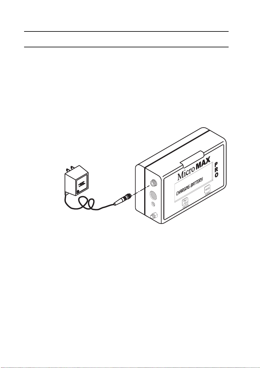
To commence charging with the charger supplied with
AC power, connect the charger plug to the instrument port
(See Figure 1) and instrument display should read
“CHARGING BATTERY”. When charging is completed,
“CHARGE COMPLETE” is displayed. The instrument is now fully
charged and ready for use.
If charging is attempted without the rechargeable battery, or
with alkaline batteries, “CHECK BATTERY” is displayed.
Figure 1 Charging the MicroMax Pro
11
Page 12

MAN-MAXPRO
REV. B.0.
2. GENERAL DESCRIPTION
2. GENERAL DESCRIPTION
The MicroMax Pro is a programmable instrument that can
monitor one, two, three, four, or with Combo-Tox sensor, up to
five gases. It combines proven sensor performance and
electronics in a small, lightweight, and easy to use monitor. It
consists of the monitor, NiMH rechargeable battery pack,
battery charger, alkaline battery holder, rubber boot with neck
strap and belt clip, dust filter, 10-foot sampling hose with filter
and water trap, calibration certificate and instruction manual.
Prior to shipment, the monitor was configured with default
alarms and other settings, tested and calibrated. After
charging, it is ready for use.
12
Page 13
MAN-MAXPRO
REV. B.0.
2. GENERAL DESCRIPTION
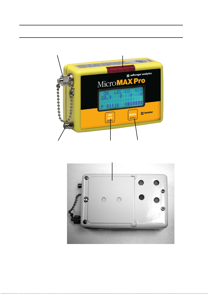
Port
Inlet ON/OFF
Switch
Battery Compartment
Large Alarm LED Bar
MODE
Switch
Rear View
Figure 2 MicroMax Pro
13
Page 14

MAN-MAXPRO
REV. B.0.
3. FEATURES
3. FEATURES
(1) Liquid Crystal Display
High contrast 4 lines by 16 character alphanumeric
display that indicates gas concentration of up to four
gases simultaneously.
(2) Display Backlighting
Automatic fiber-optic backlight provides display
readability in dim or dark environments.
(3) Automatic Toxic Sensor Recognition
Microprocessor automatically recognizes toxic sensors
when plugged in. Monitor displays corresponding gas,
sets gain, corrects alarm levels and initializes
temperature compensation.
(4) User Selectable Power Source
User has an option of powering instrument either with
the supplied NiMH rechargeable battery pack or with
four “AAA” alkaline cells (use only the cells that are
approved for use), mounted in the supplied battery
holder.
(5) User Friendly Interface
User friendly interface is intuitive for ease of use and
simplicity of operation.
(6) Extensive Programming Options
There are many programming options to customconfigure the instrument.
(7) Programmable Gas Alarms
High and low alarm levels, TWA mode for toxics,
latching or non-latching, are all user programmable.
(8) Fully Automatic Calibration
Fast, easy, accurate calibration that requires no user
adjustments or tools.
(9) Confidence Beep
User selectable confidence beep provides a visible flash
and audible beep about every 20 seconds to confirm
instrument operation.
14
Page 15

MAN-MAXPRO
REV. B.0.
3. FEATURES
(10) Voice and Display Messaging
User may select English, Spanish, French or German
for voice and display messaging.
(11) Battery Gauge
This consists of B (for battery) and a maximum of 6 bars,
as illustrated. Six bars represent full charge, while fewer
bars indicate various stages of charge. When all bars
are depleted, the instrument will run for more than an
hour, after which time a low battery alarm is indicated by
two beeps every 15 seconds. Low battery alarm will
continue for at least half an hour, after which instrument
will beep continuously and shut down. If alkaline
batteries power instrument, battery condition is
indicated on the display, not by bars, but by battery
voltage. A fresh alkaline pack will read about 5.8 volts,
and low battery warning commence anywhere from 4.0
to 4.2 volts, model dependent, while shut-off occurs
between 3.68 and 3.95 volts, model dependent.
(12) Pump or Diffusion Mode of Operation
User may choose between pump and diffusion mode of
operation. If pump is selected, ‘P’ is displayed in the
lower left corner of display and all the benefits of internal
pump operation are available. In diffusion mode, ‘D’ is
displayed. If pump mode is selected and pump fails,
instrument automatically switches to diffusion mode for
continuous operation and protection.
B
(13) Real Time Clock
User adjustable real time clock provides continuous
time display. If daylight savings time is selected, the
time will be automatically updated.
(14) User Selectable Calibration Gas Concentration
This feature allows the user to select the desired
calibration gas concentration, within specified limits, for
all sensors except oxygen.
15
Page 16

MAN-MAXPRO
REV. B.0.
3. FEATURES
(15) User Selectable LEL Conversion Factors
This feature allows instrument to accurately indicate the
LEL level for a wide range of hydrocarbons after
calibrating with the methane gas.
(16) Multiple Gas Alarm Indicators
Audible and visual alarms alert user of unsafe gas
levels.
(17) Low Flow Alarm
In pump mode, a steady audible alarm is accompanied
by a visual alarm and the display indicates “LOW FLOW”.
If alarm persists, instrument will indicate “PUMP FAIL”
and switch to diffusion mode of operation.
(18) RFI Resistant Design
High resistance to RFI (radio frequency interference)
minimizes false alarms.
(19) Charge Status Recognition
The instrument automatically shuts off if charger is
connected while monitor is on. This prevents the charger
from being used as a power source, which is not
intrinsically safe. Soon after charger is connected,
display indicates “CHARGING BATTERY”.
(20) Calibration Record
The date the instrument is last calibrated and the date
that the instrument is due for the next calibration can be
displayed on the start-up under “LAST CALIBRATED”
and “CALIBRATION DUE”.
(21) Peak, STEL and TWA
The MODE button enables display of peak reading
(highest toxic or combustible and lowest oxygen levels),
STEL (15-minute accumulated short-term exposure
level), and TWA (8-hour time weighted average) since
instrument was last turned on. The STEL and TWA will
be indicated only if “ALARM TYPE” is set to “TWA ON”.
16
Page 17

MAN-MAXPRO
REV. B.0.
3. FEATURES
(22) Low Battery Warning
Low battery warning is indicated by dual beep every
15 seconds, 30 minutes prior to shutdown. With alkaline
batteries, low battery warning occurs between 4.0 and
4.2 volts.
(23) Data Logging
The MicroMax Pro is supplied with data logging
capabilities and all necessary hardware, cables and
software. There are 2400 data points for storage of up
to 200 hours of data.
(24) Approvals
Intrinsic Safety:
• MPRO (Standard MicroMax Pro)
UL Classified ‘Class I, Divisions 1 & 2, Groups A, B,
C & D, Class II, Groups E, F & G’
• MPRO-A (Australian version)
SAA Certified Ex ia s Zone 0 IIB T3
• MPRO-M (MSHA version)
MSHA approved for intrinsic safety (Methane-Air
mixtures only)
• China ‘PATTERN APPROVAL CERTIFICATE’
EMC Standards: (Third Party Certified)
• EN 50270:1999
• EN 55011:1998
17
Page 18

MAN-MAXPRO
REV. B.0.
4. OPERATING INSTRUCTIONS
4. OPERATING INSTRUCTIONS
MICROMAX PRO
VER 5.0
ON
TESTING
PLEASE WAIT
ZEROING
PLEASE WAIT
OX LEL CO H2S
19.5 10 25 10
LOW ALARM
OX LEL CO H2S
23.5 20 35 20
HIGH ALARM
VOICE ON
READY
OX LEL CO H2S
20.9 0 0 0
P 11:52
B
Figure 3 Default Turn-on Sequence
18
Page 19

MAN-MAXPRO
REV. B.0.
4. OPERATING INSTRUCTIONS
4.1 TURN-ON
After charging the instrument, or installing fresh alkaline
batteries, turn instrument on in clean air, by depressing the
ON/OFF button until a confirming beep is heard. Release the
ON/OFF button and instrument will display the firmware
version number and “ON” before cycling through its turn-on
sequence (See Figure 3 Default Turn-on Sequence). Then
the instrument goes through “TESTING” and “ZEROING”
cycles, displays low alarm levels and high alarm levels,
indicates “VOICE ON” and “READY” and goes into normal
operating mode. In normal operating mode, gas types and
levels occupy the top two lines, the third line is blank and
available for messaging, while on the fourth line is the letter “P”
or “D”, for pump or diffusion mode of operation respectively,
the current time in 24-hour format and the battery gauge. If
alkaline batteries power instrument, battery condition is
indicated by display of battery voltage. With alkaline batteries,
voltage should be about 5.8 volts with fresh batteries, with low
battery warning occurring at between 4.0 and 4.2 volts,
depending on sensor configuration.
4.2 STANDARD MODE SEQUENCE
OX LEL CO H2S
20.1 0 16 9
PEAK READING
LEL CO H2S
USER SETUP
NO
OX LEL CO H2S
20.9 0 0 0
P 08:49
Figure 4 Default Standard Mode Sequence
19
B
Page 20

MAN-MAXPRO
REV. B.0.
4. OPERATING INSTRUCTIONS
Each standard mode option is available by depressing the
MODE button sequentially.
PEAK READING. The highest toxic and combustible gas
levels and the lowest oxygen levels. Depressing the ON/OFF
button while in this mode clears peak values.
USER SETUP. User setup mode allows pump, voice and
confidence beep to be turned on or off as desired. It is also
here that calibration is usually done, and memory cleared (See
Section 4.7 Clearing Memory). To enter the user setup mode,
keep depressing the MODE button until line 3 of display
indicates “USER SETUP”. Press the ON/OFF button to enter
user setup mode, to bypass each setting depress the MODE
button. To change any setting, depress the ON/OFF button.
For example, to change pump, voice, or confidence beep from
“ON” to “OFF” or vice versa, depress the ON/OFF button when
the appropriate menu item is displayed. To enter calibration
mode, depress the ON/OFF button when “CALIBRATE?” is
displayed(SeeSection5Calibration).
4.3 TESTING SENSORS AND ALARMS
It is recommended that proper alarm function be verified prior
to use by applying calibration or alarm check gas. Alarm check
gas (Test 1A) should be used only for instruments that contain
one or more of the 4 standard sensors (O2, LEL, CO or H2S).
For other configurations, use calibration gas with instrument in
normal operating mode. After testing, remember to clear the
peak values, or if “ALARM TYPE” is set to “TWA ON”, clear
memory. Test low flow alarm by placing finger over inlet when
in pump mode. If instrument does not go into low flow alarm
when inlet is blocked, instrument should be operated in
diffusion mode after entering the “USER SETUP” mode and
changing the pump status configuration to “PUMP OFF”.
Instrument should be serviced as soon as possible to fix the
problem.
20
Page 21

MAN-MAXPRO
REV. B.0.
4. OPERATING INSTRUCTIONS
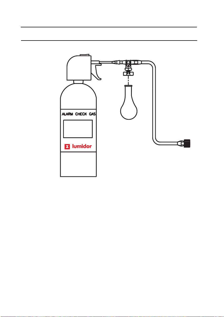
Instructions for using alarm check gas (part number Test 1A)
• Turnmonitoroninfreshairandallowittogointonormal
operating mode.
• Break shipping tab off canister.
• Attach blue balloon on to black disk on alarm check gas
hose. (See Figure 5)
• Insert red end of hose into hole in canister nozzle.
• Pinch hose (or place finger over the end of the hose) and
pulse trigger so that gas fills the balloon to its natural shape.
Do not over-inflate balloon.
• Insert other end of hose into air intake.
• All channels should be in alarm for a few seconds while gas
passes over sensors. Check display to confirm proper
operation of visual alarms for each gas. Confirm proper
operation of audible alarms.
• Remove hose from monitor and allow alarm check gas to
be purged from monitor with fresh air.
• Clear Peaks or, if “ALARM TYPE” is set to “TWA ON”, clear
memory (Please see Section 4.7 Clearing Memory).
CAUTION
Gas/Bump test should be performed in a well-ventilated
area.
21
Page 22
MAN-MAXPRO
REV. B.0.
4. OPERATING INSTRUCTIONS
Figure 5 Alarm Check Gas
4.4 CONTINUOUS MONITORING
Lumidor recommends that the supplied dust filter (part number
16PFC) be attached at all times in pump mode if the
instrument is being used in a dusty environment. Keeping dust
out increases instrument life and lowers maintenance costs.
4.5 REMOTE SAMPLING (PRETESTING)
Remote areas and confined spaces may be sampled in pump
mode prior to entry by connecting the supplied 10-foot or
longer sampling hose to the inlet fitting. The sampling hose is
usually used for pretesting only. Continuous monitoring with
the sampling hose attached reduces the number of hours of
run time available.
22
Page 23

MAN-MAXPRO
REV. B.0.
4. OPERATING INSTRUCTIONS
The following procedure is recommended:
• Turn instrument on and allow to enter normal operating
mode.
• Besureyouareinpumpmode.(“P”indicatedinline4of
display).
• Test alarm function with gas as indicated in Section 4.3
Testing Sensors and Alarms..
• Test low flow alarm as indicated in Section 4.3 Testing
Sensors and Alarms.
• Connect sampling hose to instrument. Place hose in area
to be sampled.
• Wait two minutes for full response.
• Take readings.
• Retrieve hose and disconnect from instrument.
Hose lengths up to 100 feet may be used for pretesting. Add
one second per foot to the two-minute wait for full response.
4.6 ALARMS
In the event of a gas alarm, evacuate the area immediately.
Investigate the cause of the alarm only when you are safely out
of the potentially hazardous area. Accessing the “Peak” mode
will display the gas and level that generated the alarm.
• A “warning” low gas alarm indicates a gas concentration
above the low alarm set point and is indicated by 3 beeps
from the horn, flashing LED, flashing gas range of the
sensor in alarm, and display of the word “WARNING.”
Voice will also say “WARNING” except for O2, in which
case it will say “DANGER.”
• A “danger” high gas alarm is indicative of a gas
concentration above the high alarm set point and is
indicated by 3 beeps from the horn, flashing LED, flashing
23
Page 24

MAN-MAXPRO
REV. B.0.
4. OPERATING INSTRUCTIONS
gas range of the sensor in alarm, and display of the word
“DANGER.” Voice will also say “DANGER”.
• Low flow or pump fail alarm is indicated by a continuous
audible alarm, flashing LED, and the words “LOW FLOW”
or “PUMP FAIL” displayed.
• Low battery alarm is indicated by 2 short beeps from the
horn every 15 to 20 seconds, together with the words “LOW
BATTERY’ on the display. It first occurs approximately
30 minutes prior to battery depleted alarm and shutdown.
• Battery depleted alarm is indicated by 5 audible beeps,
display of “BATTERY DEPLETED” and shutdown.
4.7 CLEARING MEMORY
Memory is automatically cleared after each calibration.
To clear memory manually:
• Depress the MODE button repeatedly until “USER SETUP”
is displayed.
• Depress the ON/OFF button to enter the user setup mode.
• Depress the MODE button 4 times until “CLEAR
MEMORY” is displayed.
• Depress the ON/OFF button once to simultaneously clear
memory and return to normal operating mode.
4.8 TURN-OFF
To turn the MicroMax Pro off, depress and hold the ON/OFF
button, and instrument will beep 4 times. After the fourth beep,
release the button, and instrument will indicate “POWER OFF”
and automatically turn itself off.
If ON/OFF button is released during countdown, instrument
will resume normal operation.
24
Page 25

MAN-MAXPRO
REV. B.0.
5. CALIBRATION
5. CALIBRATION
5.1 CALIBRATION FREQUENCY
It is important to verify accuracy on a regular basis to guard
against any unexpected loss of sensitivity due to mechanical
damage, immersion, aging, or exposure of the sensors to
poison (such as high concentration of combustible gas, tetraethel-lead, sulfides or silicone containing lubricants) present in
the atmosphere being monitored.
The safest possible course of action is to expose the sensors
to a known concentration test gas before each day’s use. This
“bump” test takes only a few seconds to accomplish. It is not
necessary to make a calibration adjustment unless readings
are off by more than 15% of the applied gas concentration. If
this procedure is followed, the calibration interval can be up to
90 days.
If your calibration procedures do not permit daily checking of
the sensors, Lumidor recommends the following procedure to
establish a safe and prudent check schedule. Initially, over a
period of a few days, check the response daily to be sure there
is nothing in your atmosphere that is poisoning the sensors. If
the instrument displays correct concentration levels after 2
weeks on this schedule, the calibration interval may be
extended to two weeks. If the instrument does not require
calibration, after 2 months on this schedule, the calibration
interval may be extended to 30 days.
WARNING
This does not preclude testing with gas on a regular basis.
Always observe your employer’s calibration and testing
schedules.
25
Page 26

MAN-MAXPRO
REV. B.0.
5. CALIBRATION
5.2 CALIBRATION PROCEDURE (WHEN ALL
CALIBRATION GASES ARE IN A SINGLE
CANISTER)
CAUTION
Calibration should be carried out only in a clean air
environment, known to be free of contaminants.
Be sure the calibration gas is within the expiration date
indicated.
• Use MODE button to scroll through mode functions to
“USER SETUP”.
• Depress ON/OFF button to enter “USER SETUP”.
• Use MODE buttontoscrollto“CALIBRATE?”
• Depress ON/OFF button to enter the calibration mode.
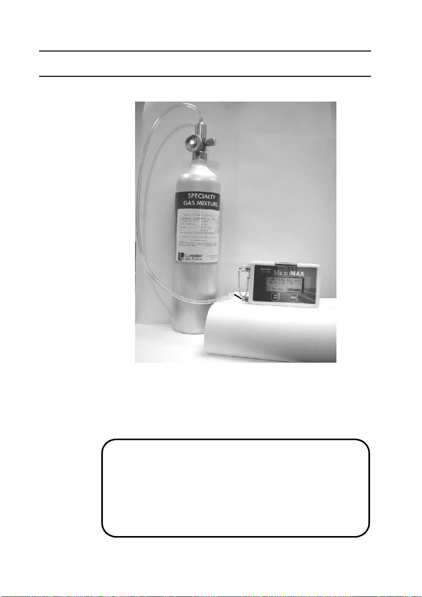
• Instrument will count down to 0.
• Apply calibration gas when “APPLY GAS” is displayed.
(See Figure 6).
• Instrument will display “CALIBRATING” and count down to
0.
• When “CAL COMPLETE” is displayed, observe that all
sensors calibrated are displayed below “CAL
COMPLETE”. Any sensor not displayed is not
calibrated. Remove gas and turn off gas flow.
• Instrument will go into a “PURGING” countdown to 0.
• After purging, instrument automatically clears memory.
• This calibration process is now complete.
26
Page 27
MAN-MAXPRO
REV. B.0.
5. CALIBRATION
Figure 6 Calibrating the MicroMax Pro
5.3 CALIBRATION PROCEDURE (WHEN NOT
ALL CALIBRATION GASES ARE IN A
SINGLE CANISTER)
CAUTION
Calibration should be carried out only in a clean air
environment, known to be free of contaminants.
Be sure the calibration gas is within the expiration date
indicated.
27
Page 28

MAN-MAXPRO
REV. B.0.
5. CALIBRATION
CAUTION
Please refer to Appendices K and L for important
additional information.
• Use MODE button to scroll through mode functions to
“USER SETUP”.
• Depress ON/OFF button to enter “USER SETUP”.
• Use MODE buttontoscrollto“CALIBRATE?”.
• Depress ON/OFF button to enter the calibration mode.
• Instrument will count down to 0.
• Apply the first calibration gas, or gases, when “APPLY
GAS” is displayed. (See Figure 6)
• Instrument will display “CALIBRATING” and count down to
0.
• When “CAL COMPLETE” is displayed, observe which
sensors are calibrated and displayed below “CAL
COMPLETE”. Remove gas and turn off gas flow.
• Depress the ON/OFF switch and instrument will display
“APPLY GAS”.
• Apply the second calibration gas.
• Instrument will display “CALIBRATING” and count down to
0.
• When instrument displays “CAL COMPLETE”, observe
whether all sensors are calibrated and displayed below
“CAL COMPLETE”. Remove gas and turn off gas flow.
• If all sensors were displayed below “CAL COMPLETE”,
instrument is fully calibrated and will display “PURGING”,
count down to 0 and clear memory. The calibration process
is complete.
28
Page 29

MAN-MAXPRO
REV. B.0.
5. CALIBRATION
• If a third calibration gas needs to be applied, after
instrument displays “CAL COMPLETE”, depress the ON/
OFF button and follow the instructions on the display.
• When “CAL COMPLETE” is displayed, remove gas and
turn off gas flow.
• Instrument will purge itself while counting down to 0, and
clear memory.
• The calibration process is now complete.
5.4 ZEROING
CAUTION
Zeroing should be carried out only in a clean air
environment, known to be free of contaminants.
There are three ways to zero the instrument:
• Zeroing is done, automatically, each time the instrument is
calibrated.
• Zeroing is done, automatically, each time the instrument is
turned on if the “AUTO ZERO” feature is selected in the
supervisory mode. Please refer to Section 6.6 Auto-
zeroing.
• Zeroing may be done manually without doing a full
calibration by entering the calibration mode (please refer to
Section 5.2 Calibration Procedure (when all calibration
gases are in a single canister)) and, anytime while the
instrument is zeroing and counting down from 30 seconds
to 0, depress and hold down the MODE button for at least
3 seconds. Instrument will not immediately exit, but will
complete the zeroing cycle, count down to 0, and then exit
the calibration mode.
29
Page 30

MAN-MAXPRO
REV. B.0.
6. PROGRAMMING
6. PROGRAMMING
6.1 PROGRAMMING OPTIONS
Powerful programming options allow user to customize the
MicroMax Pro. Some options are available in the user set-up
mode (See Appendix D Mode Sequence, User Set-up Mode)
but the majority of these options are available only in
supervisory mode. ALL PROGRAMMING OPTIONS CAN
ALSO BE ACCOMPLISHED THROUGH THE MAXPRO LOG
SOFTWARE, USING THE UPLOAD FUNCTION. THIS IS BY
FAR THE MOST CONVENIENT AND EFFICIENT METHOD
AND IS STRONGLY RECOMMENDED. If a computer is not
available, programming may be accomplished manually in
supervisory mode, using the MODE and ON/OFF buttons. To
enter the supervisory mode, depress and hold the MODE
button for 5 seconds, during the “TESTING” phase of the startup sequence. The general structure of the supervisory mode
is to depress the MODE button to bypass an option, or use the
ON/OFF button to enter the option’s menu and make a
change. Where a menu has two options only for example,
“ON” or “OFF”, depressing the ON/OFF switch once
simultaneously accomplishes three functions; entering the
menu, changing the option and exiting the menu.
The following are all programmable:
• LEL gas type (CAUTION: This option is not operative
with the % by volume sensor.)
• Date format, date/time, daylight savings time
• Datalog frequency
• Auto-zero during start-up sequence
• Last calibration date displayed or not during start-up
sequence
• Latching or non-latching alarms
• Calibration gas level
• High alarm set points
30
Page 31

MAN-MAXPRO
REV. B.0.
6. PROGRAMMING
• Low alarm set points/Low alarm disable (except O2)
• Calibration due date displayed or not during start-up
sequence, calibration due frequency
• Language choice
• TWA alarm on or off
• Factory default settings
• Calibration
6.2 SELECTING LEL GAS TYPE
The LEL sensor is designed to provide its highest sensitivity to
Methane, See Appendix A Specifications - Section (O)
General). For users detecting methane or natural gas, the
standard calibration methods, using methane, with the “SEL
LEL GAS TYPE” set to Methane, is acceptable. This is the
standard default setting.
For users that need to monitor for a gas on the list, other than
methane or natural gas, there are two options:
(1) For the highest possible accuracy, it is always better to
calibrate the instrument with the desired target gas (that
is, the gas being monitored) i.e. Pentane. This is done
by following the calibration procedure in Section 5.2
Calibration Procedure (when all calibration gases are in
asinglecanister)and leaving the “SEL LEL GAS TYPE”
setting at Methane.
(2) If the target gas (let’s use Pentane as an example) is not
available, acceptable results may be obtained by
enteringthe“SELLELGASTYPE”functioninthe
supervisory mode, selecting “Pentane”, and using the
procedure in Section 5.2 Calibration Procedure (when
all calibration gases are in a single canister) to do a
standard calibration with methane gas. This action
enables the instrument to indicate the correct LEL
reading when monitoring Pentane. See Appendix A
31
Page 32

MAN-MAXPRO
REV. B.0.
6. PROGRAMMING
Specifications of this manual, provides data on the
relative span of detectable gases. The 5 gases listed in
the “SEL LEL GAS TYPE” function, with their relative
spans, are:
Methane 100
Propane 63
Pentane 50
Hexane 46
Xylene 31
From these five gases, select the one with a relative
span value closest to the relative span of your target
gas. For example, if your target gas is benzene (relative
span 44 per Appendix A Specifications - Section (O)
General) select hexane whose relative span of 46 is
closest to that of benzene and calibrate with the
supplied methane gas. To program the instrument for
the desired LEL gas type, enter the supervisory mode
(Section 6.1 Programming Options) and depress the
ON/OFF buttontoenterthe“SELLELGASTYPE”
menu. Use the MODE button to select the gas type and
the ON/OFF button to exit this menu sequence.
6.3 SETTING DATE FORMAT
This function enables user to choose the correct date format.
The default date format is MM/DD/YYYY (MONTH/DAY/
YEAR), as is customary in the USA. To determine to which
date format the instrument is set, enter the supervisory mode
(Section 6.1 Programming Options) and use the MODE button
to scroll down to “DATE FORMAT”. If set for USA, display will
indicate:
DATEFORMAT
MM/DD
If this format is acceptable, and there is no need to set the date
and time, depress the MODE button to bypass the function. If,
however, DD/MM/YYYY (DAY/MONTH/YEAR) format is
32
Page 33

MAN-MAXPRO
REV. B.0.
6. PROGRAMMING
desired, depress the ON/OFF button twice, (once to enter the
menu, and again to change the date format) to:
DD/MM
15/06/2000-13:50 (These numbers represent current date &
time)
If there is no reason to change the date or time, depress the
ON/OFF button a further twelve times to exit.
6.4 SETTING DATE/TIME
To set date and time enter the supervisory mode (Section 6.1
Programming Options) and use the MODE button to scroll to
“DATE FORMAT”. Depress the ON/OFF button to enter the
menu. Depress the MODE button. The first digit on the left will
start to flash. Depress the ON/OFF switch to accept the
flashing number and move one number to the right, or use the
MODE button to change the flashing number to the desired
value. If the date format is MM/DD, the first two digits on the
left represent the current month and the first digit must be
either a 0 or a 1. Let us set the date to September 2, 2002. We
need 09 to represent the month of September. If 0 is flashing,
depress the ON/OFF switch. This accepts the 0 on the left and
we may now use the MODE switch to set the next number to
9. Depress the ON/OFF button to accept the 9 and the month
is correctly set to 09. The next digit on the right is now flashing
and the MODE button is used to select 0. Depress the ON/OFF
button to accept the 0, the MODE button to select 2, and the
ON/OFF button to accept 2. To set the year, use the MODE
button to select 2, the ON/OFF buttontoacceptthe2.Usethe
MODE button to select the 0 and depress the ON/OFF button
to accept. Use the MODE button to select 0 again and depress
the ON/OFF button to accept. Use the MODE buttontoselect
the 2 and the ON/OFF button to accept. This completes the
date settings. To continue and set the correct time to 14:45
(2:45PM), use the MODE button to select 1 and the ON/OFF
button to accept the 1. Use the MODE button to select 4 and
depress the ON/OFF button to accept the 4. Use MODE switch
33
Page 34

MAN-MAXPRO
REV. B.0.
6. PROGRAMMING
to select 4 and depress the ON/OFF switch to accept the 4.
Use MODE to select 5 and ON/OFF to accept and exit this
menu.
The date and time are now correctly set. The “DAYLIGHT
SAVING” time menu now appears.
DAYLIGHT SAVING
OFF
Default is “OFF”. Depress the MODE button to accept this
setting and exit, or depress the ON/OFF buttontoturnon
daylight savings and exit.
6.5 SELECTING DATA LOG FREQUENCY
The data log frequency is the time interval between logged
readings and may be set at 1, 2, 3, 4 or 5 minutes. The time
internal does not affect the total number of data points. The
total number of data points is fixed at 2400 so if a 1-minute
interval is chosen, 40 hours of data may be logged. If a
5-minute interval is chosen, 200 hours of data may be logged.
The default setting is 1-minute so no action need be taken if
this interval is acceptable.
To change the data log frequency, access the supervisory
mode (See Section 6.1 Programming Options) and use the
MODE button to scroll down to “DATA LOG-FREQ”. Depress
the ON/OFF button to enter the menu sequence, then use the
MODE button to select 1,2,3,4 or 5-minute interval. Depress
the ON/OFF button to accept the selection and exit.
6.6 AUTO-ZEROING
The factory default setting is automatic zeroing during start-up,
each time the instrument is turned on. If this is not acceptable,
the auto-zero function during start-up may be turned off by
entering the supervisory mode (Section 6.1 Programming
Options) and using the MODE button to scroll down to:
AUTOZERO
ON
34
Page 35

MAN-MAXPRO
REV. B.0.
6. PROGRAMMING
Use the ON/OFF button to enter the menu, change the setting
to “OFF”, and exit the menu. Since zeroing is always done
during the calibration process, proper instrument operation will
be maintained if calibration is always carried out in a clean air
environment.
6.7 DISPLAYING LAST CALIBRATION DATE
The instrument may be programmed so that the last calibration
date is displayed during the start-up routine. The factory
default setting has this function turned on. If it is desired to
have the last calibration date displayed each time the
instrument is turned on, it is necessary to enter the supervisory
mode (See Section 6.1 Programming Options) and use the
MODE button to scroll down to:
LAST CALIBRATED
ON
Depress the ON/OFF button to enter the menu, turn the
function on and exit.
6.8 SELECTING LATCHING/NON-LATCHING
GAS ALARMS
The factory default setting is non-latching alarms (latching
alarms “OFF”). This means that the instrument will cease
alarming when gas levels fall below the alarm set points. If
latching alarm (latching alarms “ON”) is chosen, the instrument
will continue to alarm when gas levels fall below alarm set
points and may be turned off only when the user depresses the
ON/OFF button. To turn on the latching, enter the supervisory
mode (Section 6.1 Programming Options) and use the MODE
button to scroll down to “LATCHING ALARMS”:
LATCHING ALARMS
OFF
Depress the ON/OFF button once to make the change and exit
the menu.
35
Page 36

MAN-MAXPRO
REV. B.0.
6. PROGRAMMING
6.9 SETTING CALIBRATION GAS LEVEL
The defaults, as well as the full range of programmable
calibration gas levels, are set out in Appendix A Specifications -
Section (K) User Programmable Calibration Gas Levels.Ifitis
desired to change the default levels, enter the supervisory
mode (See Section 6.1 Programming Options) and use the
MODE button to scroll down to the “CAL GAS LEVEL” menu,
which (depending on model) looks like:
LEL CO H2S
50 50 25
CAL GAS LEVEL
If there is a good reason to change these factory default
values, depress the ON/OFF button to select the LEL.
LEL
50 50 25
CAL GAS LEVEL
If the displayed calibration gas level (50% LEL in this example)
is acceptable, depress the ON/OFF button to accept and move
to the next gas. Otherwise, if a change is desired, use the
MODE button to increase or decrease the level by 5% LEL
increments within the range from 5% LEL to 60% LEL. To set
the calibration gas level for carbon monoxide (or other gas
sensor in Tox 1 position), depress the ON/OFF button and CO
is selected.
CO
50 50 25
CAL GAS LEVEL
Either depress the ON/OFF button to accept calibration gas
level displayed, or use the MODE button to increase or
decrease the calibration gas level, by 5ppm increments, to the
desired value in the range from 50ppm to 300ppm.
CAL GAS LEVEL
50 50 25
H2S
36
Page 37

MAN-MAXPRO
REV. B.0.
6. PROGRAMMING
Depress the ON/OFF button to select H2S (or other gas
sensor in Tox 2 position). Depress the ON/OFF button to
accept the level displayed or use the MODE buttontoincrease
or decrease the desired value, by 5ppm increments, in the
range from 5ppm to 25ppm. To exit the menu, depress the ON/
OFF button.
6.10 SETTING HIGH ALARM
The defaults, as well as the full range of programmable high
alarm set points, are set out in Appendix A Specifications Section (I) User Programmable High and Low Alarm Set
Points. To change the default levels, use the MODE button to
scroll down to:
OX
HIGH ALARM SET
23.5
Depress the ON/OFF button to select the gas (i.e. oxygen) for
which the alarm is being set.
OX
23.5
HIGH ALARM SET
LEL CO H2S
20 35 20
20 35 20
If the alarm level displayed (23.5 in this example) is
acceptable, depress the ON/OFF button to accept and select
the next gas. If a change in value is desired, use the MODE
button to change the high alarm setting to the desired value.
Depress the ON/OFF button to select the next gas. Follow this
same procedure for the other gases and depress the ON/OFF
button to exit this menu.
6.11 SETTING LOW ALARM
The defaults, as well as the full range of programmable low
alarm set points, are set out in Appendix A Specifications Section (I) User Programmable High and Low Alarm Set
Points. To change the default levels, use the MODE button to
scroll down to:
37
Page 38

MAN-MAXPRO
REV. B.0.
6. PROGRAMMING
OX LEL CO H2S
LOW ALARM SET
19.5 10 25 10
Depress the ON/OFF button select the gas for which the alarm
is being set. The procedure for low alarm is identical to that for
setting high alarm in Section 6.10 Setting High Alarm,towhich
reference may be made. A zero value disables corresponding
low alarm, with the exception of O2.
6.12 DISPLAYING CALIBRATION DUE DATE
The instrument is capable of displaying the calibration due
date in start-up sequence. The default setting is “OFF”. If it is
desired that instrument displays “CALIBRATION DUE” during
the start-up sequence, enter the supervisory mode (See
Section 6.1 Programming Options) and use the MODE button
to scroll down to:
CAL DUE AUTO
OFF
To turn on this function, depress the ON/OFF button, and
instrument will display:
CAL DUE FREQ
30
The “30” is the factory default calibration frequency of 30 days.
If this frequency is acceptable, depress the MODE button to
accept and exit the menu. To change the calibration
frequency, depress the ON/OFF button and use the MODE
button to increment the left digit to the desired value in the
range 0 to 9, depress the ON/OFF button to select the second
digit, and use the MODE button to set the desired number in
the range 0 to 9. The maximum calibration frequency allowed
is 90 days. Depress the ON/OFF button to exit the menu. It is
now required to calibrate the instrument to make these
changes effective. This is very important for the instrument to
initialize the process. Use the MODE button to scroll down to
38
Page 39

MAN-MAXPRO
REV. B.0.
6. PROGRAMMING
“CALIBRATE?” and calibrate the instrument. (See Section 5
Calibration)
6.13 CHOOSING A LANGUAGE
The default language is English. If a change to another
language is desired, enter supervisory mode (See Section 6.1
Programming Options) and use the MODE button to scroll
down to:
LANGUAGE SET
ENGLISH
To enter the menu, depress the ON/OFF button and use the
MODE button to select English, Spanish, French or German.
Depress ON/OFF to accept the selection and exit the menu.
6.14 SELECTING IMMEDIATE ALARM MODE/
TWA ALARM MODE
There are two types of alarm modes to choose from:
immediate alarm mode and TWA alarm mode.
• In the immediate alarm mode, two types of alarms are
available: immediate low and immediate high alarms. The
default values for these alarms are pre-set (See Appendix A
Specifications - Section (I) User Programmable High and
Low Alarm Set Points) at the factory but are user
programmable.
• In the TWA alarm mode, three types of alarms are
available: TWA, STEL, and instantaneous alarms. TWA is
a time-weighted average over an 8-hour period. STEL is
the short-term exposure limit over a 15-minute period. The
instantaneous alarm represents an exposure level that
generates an alarm instantly. The values for these alarms
are pre-set (See Appendix A Specifications - Section (J)
Time Weighted Averages (Only if "TWA ON" is selected)
(Toxic sensors only)) at the factory and cannot be changed.
39
Page 40

MAN-MAXPRO
REV. B.0.
6. PROGRAMMING
6.15 RESTORING FACTORY DEFAULTS
This supervisory option restores the instrument to all factory
default settings.
DEFAULT?
A user who modified one or more settings in supervisory mode
may depress the MODE button to bypass this function for the
changes to take effect, or depress the ON/OFF button to
abandon his changes and revert to the factory default settings.
6.16 CALIBRATION IN SUPERVISORY MODE
This option allows calibration in the supervisory mode. To
bypass, depress the MODE button. To calibrate depress the
ON/OFF button and follow the calibration procedure in
Section 5.2 Calibration Procedure (when all calibration gases
are in a single canister).
40
Page 41

MAN-MAXPRO
REV. B.0.
7. DATA LOGGING
7. DATA LOGGING
WARNING
Do not connect the instrument to a PC in a potentially
hazardous environment.
7.1 SYSTEM REQUIREMENTS
• PC or IBM-compatible system
• 166 MHz or higher
• 16 MB of RAM or more
• 30 MB of free disk space
• Windows 98 SE, Windows Me, Windows NT4.0 (with
Service Pack 6a installed), Windows 2000, or Windows XP
• CD-ROM drive
• RS-232 serial port
• VGA monitor (with the screen resolution set to 800x600 or
higher)
7.2 GENERAL INFORMATION
The MaxPro Log software program for Windows is on a single
CD and provides the tool necessary to transfer, save, retrieve,
view, and print the data recorded in the MicroMax Pro
instrument. It is a full function program that does not require an
additional database program. It contains a README.doc file
and help content with all information needed for installing,
navigating, and using the program.
This program is compatible for use with any MicroMax Pro
instruments.
7.3 PROGRAM INSTALLATION
• Place the program CD into the CD-ROM drive.
41
Page 42

MAN-MAXPRO
REV. B.0.
7. DATA LOGGING
• If the installation program runs automatically, skip to the
next step. Otherwise, go to Start à Run, then type
X:\LUMIDORSETUP, where X represents the drive letter of
your CD-ROM drive. In most cases, this will be
D:\LUMIDORSETUP or E:\LUMIDORSETUP.
• Follow on-screen instructions to complete installation.
CAUTION
Make sure that your computer’s system clock and time
zone are correct by double-clicking on the current time
located on the Windows taskbar. Confirm/correct the date,
time, and time zone and click OK.
7.4 UNINSTALL PROCEDURE
For Windows XP users, go to Start à Control Panel. For other
Windows users, go to Start à Settings à Control Panel.
• When the Control Panel opens, double-click the Add/
Remove Programs icon.
• In the Add/Remove Programs dialog, select MaxPro Log.
• For Windows XP and Windows 2000 users, click Remove.
For other Windows users, click on Add/Remove.
• Follow on-screen instructions to uninstall the program.
7.5 STARTING THE PROGRAM
Go to Start à Programs à Lumidor MaxPro à MaxPro. This
brings up the program.
• Connect one end of the supplied download cable to an
available COM port on your computer.
• Click on the Communication menu.
• Click on Select Port/Time Zone. The Select Port and Time
Zone dialog box appears.
42
Page 43

MAN-MAXPRO
REV. B.0.
7. DATA LOGGING
• In this dialog box, select the appropriate COM port and time
zone. The COM ports that exist and are available appear as
possible selections. Make sure your port selection agrees
with the COM port on your computer that the download
cable is connected to. Click on OK to return to the Main
Screen (See Figure 7).
7.6 DOWNLOADING INFORMATION FROM
THE MICROMAX PRO
The Download function allows you to transfer data from the
instrument to the computer.
• Follow procedures indicated in Section 7.5 Starting the
Program.
• Turn on the instrument and allow it to go into normal
operating mode.
• Click on the Communication menu, then on Download, or
simply click on the Download button on the toolbar of the
Main Screen. The Download Data/Instrument Parameters
dialog box appears.
• In this dialog box, select Data (for downloading instrument
parameters, logged gas readings, and calibration data) or
Instrument Parameters (for downloading instrument
parameters), and click on OK. The following will appear on
the screen: “Is the cable connected and the instrument
ready?”
WARNING
Choosing the download instrument parameters option
dumps all logged data in the instrument and the data is not
saved in the program.
• Connect the instrument interface end of the download
cable to the port of the instrument.
43
Page 44

MAN-MAXPRO
REV. B.0.
7. DATA LOGGING
• Click on Yes. The instrument will start to count up. This
count also takes place on the computer screen.
• After all data has been transferred, the instrument displays
“DATA SENT”. Depending on the firmware version, the
instrument either shuts itself off, or continues to run in the
normal operating mode. When the computer screen displays
“Transfer complete”, click OK.
• For downloading instrument parameters, click the Upload/
Modify Instrument Parameters button on the tool bar and
the parameters will be displayed in a dialog box. For
downloading data, type your last name, first name, and
location, when prompted to do so. Then, click OK.
WARNING
All fields, including last name, first name, and location,
must be entered in order to save the downloaded data.
The maximum length to be entered for last name, first
name, and location is 14, 14, and 20 alphanumeric
characters, respectively.
Downloadingatthesamedateandtimeforaparticular
instrument is not allowed. For example, if you download
data from an instrument having serial number 1234 at 3:30
p.m. on December 8, 2002, and you try to download again
with the same instrument at the same date and time as
above, it will not save any data for this new download.
• Wait a moment for the computer to store the information.
Now, data from the most recent download is displayed on
the Main Screen and the file relating to this download can
be accessed from the Open dialog box.
44
Page 45

MAN-MAXPRO
REV. B.0.
7. DATA LOGGING
7.7 DISPLAYING AND PRINTING DATA
7.7.1 Main Screen
Information on the Main Screen includes the following (See
Figure 7):
• User information (employee’s name, instrument’s serial
number and user ID)
• Download information (date, time, and location that data is
downloaded)
• Gas data (gas types, measurement units, peaks, TWA, and
number of alarms)
Note: In user-programmable immediate alarm mode, the
number of alarms equals to the total number of
immediate high and immediate low alarms for O2, a
combustible or toxic gas. In TWA alarm mode, it
represents the total number of instantaneous alarms for
a toxic gas, or the total number of immediate high and
immediate low alarms for O2 or a combustible gas.
• Alarm levels (immediate low, immediate high, TWA, STEL
and instantaneous alarm levels)
• Note relating to a download
• Histogram (logged gas readings)
Note: The histogram is separated into groups. Each time the
instrument is turned on, or when a new day begins
during data logging, a new group is created and a new
date and time are displayed for that group.
• When a gas alarm occurs, it indicates so in front of the gas
reading in the histogram. The letters T, S, I, L, and H are
used for alarm indication. In the immediate alarm mode, L
and H represent immediate low and immediate high alarm,
respectively. In the TWA alarm mode, T, S, and I represent
TWA alarm, STEL alarm, and instantaneous alarm,
respectively, for toxic gases only, while L and H represent
45
Page 46

MAN-MAXPRO
REV. B.0.
7. DATA LOGGING
immediate low and immediate high alarm, respectively, for
O2 or combustible gases. On some occasions, TWA,
STEL, or instantaneous alarms can occur simultaneously.
As a result, any combination of those three types of alarm
would be displayed before the gas reading.
Main Screen menu and toolbar
Main Screen data
Figure 7 A screenshot of the Main Screen.
• To view all the available data files, click on the File menu
and then on Open, or simply click on the Open button on
the toolbar. A list appears with all stored files.
46
Page 47

MAN-MAXPRO
REV. B.0.
7. DATA LOGGING
• For your convenience, information in this list can be sorted
in ascending order by Employee, Serial #, Date, Time, or
Location. To sort by any one of the above, simply click on
the corresponding heading.
• To select a file, click on the desired employee name.
– To open the file, click on Open to display all the data for
that specific download, or simply double-click on the
desired file.
– To delete the file, click on Delete and the following
appears: “Are you sure that you want to delete the
selected data file?” Click on Yes to delete.
• To print all information from the Main Screen, click on the
File menu and click on Print (or simply click on the Print
button on the toolbar of the Main Screen). You can choose
to print all or to print only specified pages.
• To print preview all information from the Main Screen, click
on the File menu and click on Print Preview (or simply click
on the Print Preview button on the toolbar of the Main
Screen). On the print preview screen, you can view the next
page, view the previous page, view one or two pages at a
time, zoom in on the document, zoom out from the
document, and close the print preview screen to return to
the Main Screen.
7.7.2 Graph Screen
Information on the Graph Screen includes the following (See
Figure 8):
• User information (employee’s name, instrument’s serial
number and user ID)
• Download information (date, time, and location that data is
downloaded)
• Graph limits (date, start time, and end time for which the
graphs are plotted)
47
Page 48

MAN-MAXPRO
REV. B.0.
7. DATA LOGGING
• Graphs in different groups
Note: The group number for the graphs corresponds with the
one for the histogram. A curve cannot be plotted for a
group with fewer than two data points.
Graph Screen menu and toolbar
Graph Screen data
Figure 8 A screenshot of the Graph Screen.
• To display the graphs, click on the View menu and then on
Graphs (or simply click on the View Graphs button on the
toolbar of the Main Screen). A group of 4 curves will be
displayed (See Figure 8).
48
Page 49

MAN-MAXPRO
REV. B.0.
7. DATA LOGGING
• To view the graphs of another group, click on the tab of the
corresponding group number.
• To view an enlarged single graph, simply double-click on
the desired graph.
– To print an enlarged single graph, click on the Print
Graph button.
– To return to the Graph Screen, click on the Close button.
• To focus on a particular time span of the graphs, enter the
desired start time and end time and click on the Refresh
Graphs button on the Graph Screen.
• To display the immediate high alarm level and the
immediate low alarm level on the graphs, check the Imm/Hi
Alarm and Imm/Lo Alarm boxes, respectively.
• To print the graphs, click on the Graphs menu and then on
Print (or simply click on the Print button on the toolbar of the
Graph Screen).
• To return to the Main Screen, click on the Graphs menu and
then click on Close (or simply click on the Close button on
the toolbar of the Graph Screen).
7.7.3 Current Calibration Records
Each calibration record contains the following (See Figure 9):
• Date and time that calibration took place
• Pre-calibration readings (for up to 4 gases)
• Post-calibration readings (for up to 4 gases)
• An asterisk symbol (*) to indicate a note is attached
Note: For calibration readings, “Fail” indicates a calibration
failure, and “N/A” indicates that a gas sensor is missing.
49
Page 50

MAN-MAXPRO
REV. B.0.
7. DATA LOGGING
Figure 9 A screenshot of the Current Calibration dialog box.
• To display the current calibration records, click on the View
menu and then on Current Calibration (or simply click on
the View Current Calibration button on the toolbar of the
Main Screen). A list of all calibration records is displayed for
the instrument in that download (See Figure 9).
• To delete a calibration record, select the record and click on
the Delete Record button.
WARNING
Keep in mind that current calibration records are subsets
of the calibration history, so any records deleted from
either the Current Calibration dialog or the Calibration
History dialog are permanently removed.
• To add a note to a calibration record, select the record and
click on the Add/View Note button. It brings up the
Calibration Note dialog box. In this dialog box, type the note
and then click on Save. An asterisk (*) is displayed at the
end of the record, indicating that a note is attached.
Note: An ellipse mark (…) at the end of a record indicates that
a note can be associated with that record.
50
Page 51

MAN-MAXPRO
REV. B.0.
7. DATA LOGGING
• To print the current calibration records for that download
while on the Current Calibration dialog box, check on the
“w/ Note” check box to indicate all the attached notes are to
be printed along with the records (or uncheck it to print
without the notes) and click on Print Records.
7.7.4 Calibration History
Each calibration record contains the following (See
Figure 10):
• Date and time for which calibration takes place
• Pre-calibration readings (for up to 4 gases)
• Post-calibration readings (for up to 4 gases)
• An asterisk symbol (*) to indicate a note is attached
Note: For calibration readings, “Fail” indicates a calibration
failure, and “N/A” indicates that a gas sensor is missing.
51
Page 52

MAN-MAXPRO
REV. B.0.
7. DATA LOGGING
Figure 10 A screenshot of the Calibration History dialog box.
• To display the calibration history, click on the View menu
and then on Calibration History (or simply click on the
Calibration History button on the toolbar of the Main
Screen). A calibration history is displayed for the selected
instrument (See Figure 10).
• To select an instrument, select the serial number from the
Serial Number drop-down box, or enter the serial number
manually in the box and click Find. For example, for an
instrument with serial number 1234, append two 0’s in the
front to make it a 6-digit number, i.e. 001234, and click Find.
• To delete a calibration record, select the record and click on
the Delete Record button.
52
Page 53

MAN-MAXPRO
REV. B.0.
7. DATA LOGGING
WARNING
Keep in mind that the current calibration records are
subsets of the calibration history, so any records deleted
from either the Current Calibration dialog or the Calibration
History dialog are permanently removed.
• To add a note to a calibration record, select the record and
click on the Add/View Note button. It brings up the
Calibration Note dialog box. In this dialog box, type the note
and then click on Save. An asterisk (*) is displayed at the
end of the record, indicating that a note is attached.
Note: An ellipse mark (…) at the end of a record indicates that
a note can be associated with that record.
• To print the calibration history while on the Calibration
History dialog box, check on the “w/ Note” check box to
indicate all the attached notes are to be printed along with
the history (or uncheck it to print without the notes) and click
on Print History.
7.7.5 Instrument Parameters
To display the instrument parameters, click on the
Communication menu and then on Upload/Modify Instrument
Parameters (or simply click on the Upload/Modify Instrument
Parameters button on the toolbar of the Main Screen). The
Upload/Modify Instrument Parameters dialog box appears
(See Figure 11). Parameters in this dialog box can be
modified for uploading purposes.
53
Page 54

MAN-MAXPRO
REV. B.0.
7. DATA LOGGING
Figure 11 A screenshot of the Upload/Modify Instrument Parameters
dialog box.
The upper section consists of 19 instrument parameters, each
of which must have accurate information.
• Serial Number: The serial number is the S/N marked on
your MicroMax Pro instrument. Prior to downloading,
MAXPRO is displayed. After downloading, your instrument’s
serial number is indicated in this field. Zeroes are placed in
front of the serial number to make it a 6-digit number. It is set
at the factory and cannot be modified by the user.
• MFG Date: The MFG Date is the manufacture date of your
MicroMax Pro instrument. Prior to downloading, 99/12 is
displayed. After downloading, your instrument’s manufacture
date is indicated in this field. It is set at the factory and cannot
be modified by the user.
54
Page 55

MAN-MAXPRO
REV. B.0.
7. DATA LOGGING
• Current Date: The current date is in MM/DD/YYYY format.
This field allows user to transfer the current date to the
instrument. To change the current date, click on the down
arrow to display a calendar and then click on the correct
date.
• Current Time: The current time is in a 24-hour format. The
following are a few examples of the time conversion from a
12-hour format to a 24-hour format.
12-hour format 24-hour format
2:00 p.m. = 14:00
10:15 a.m. = 10:15
12 noon = 12:00
12 midnight = 00:00
• Daylight Saving: This feature allows the instrument to be
adjusted to daylight saving time. The default setting is OFF.
To turn on this feature, select ON for Daylight Saving.
• User ID: The user ID is a user identification number. It is
not required to enter the user ID. To create or change it,
enter a value up to 12 characters.
• Time Zone: This feature allows the user to view the
selected time zone, depending on their location. The
default setting is (GMT – 07:00) Mountain Time. To select
another time zone, click on the Config button from the Main
Screen’s toolbar and select the appropriate time zone.
• Language: There are four kinds of languages available in
the MicroMax Pro instrument: English, Spanish, French
and German. Both visual and audible messages can be set
for the chosen language. The default setting is English. To
select another language, click the down arrow and select
from the list.
• Data Logging Interval: The interval between data points
displayed in the histogram. There are 5 different data
logging intervals to choose from 1, 2, 3, 4, and 5 minutes.
The default setting is 1 minute. To change the interval, click
55
Page 56

MAN-MAXPRO
REV. B.0.
7. DATA LOGGING
the down arrow and select from the Data Logging Interval
list.
• LEL Gas Type: There are 5 LEL gas types available:
methane, propane, pentane, hexane, and xylene. To
change the LEL gas type, select the appropriate type from
the list.
• Auto-zero: If this feature is enabled on the MicroMax Pro,
the instrument will automatically zero itself during the startup routine. (Regardless, zeroing takes place each time a
calibration is completely done). The default setting is ON.
To turn off this feature, select OFF for Auto-zero.
• Pump: Pump is required for pre-testing and calibration.
However, users may at times prefer to operate the
instrument in diffusion mode, for example, when longer run
time is desired. The default setting is ON, which represents
thepumpmode.Togointodiffusionmode,selectOFFfor
Pump.
• TWA Alarm: User can choose between two alarm settings:
TWA alarm mode and immediate alarm mode. To turn on
the TWA alarm mode, set the TWA Alarm option to ON. To
turn on the immediate alarm mode, set the TWA Alarm
option to OFF. The factory alarm setting is immediate
alarm, with values chosen to provide earlier warning than
the STEL and TWA settings. The immediate high and
immediate low alarms are user-programmable. STEL is the
short-term exposure limit over a 15-minute period. TWA is
the time weighted average over an 8-hour period.
Instantaneous alarm is an exposure level that generates an
alarm instantly.
• Latching Alarm: If the instrument goes into gas alarm and
latching alarm is set to OFF, the alarm will cease when gas
levels fall below the alarm level. If latching alarm is set to
ON, the alarm will continue even if gas levels fall below the
alarm level. In this case, the latching alarm will stop only
when the ON/OFF button is depressed momentarily. The
56
Page 57

MAN-MAXPRO
REV. B.0.
7. DATA LOGGING
default setting is OFF. To turn on this feature, select ON for
Latching Alarm.
• Voice: This feature enables voice messaging while
operating the instrument. The default setting is ON. To turn
off this feature, select OFF for Voice.
• Confidence Beep: The confidence beep is a visual flash,
accompanied by an audible beep every 20 seconds to
reassure user that the instrument is working. The default
setting is OFF. To turn on this feature, select ON for
Confidence Beep.
• Display Last Calibration Date: This feature allows the
date for the last calibration to be displayed in the start-up
routine each time the instrument is turned on. The default
setting is OFF. To turn on this feature, select ON for Display
Last Calibration Date.
• Display Calibration Due Date: This feature allows the
calibration due date to be displayed in the start-up routine
each time the instrument is turned on. The default setting is
OFF. To turn on this feature, select ON for Display
Calibration Due Date.
• Calibration Frequency: Calibration frequency represents
the number of days between calibrations. If Display
Calibration Due Date is selected, Calibration Frequency
must be specified. The default period is 30 days. To change
this option, choose between 1 and 90 days for Calibration
Frequency. After this period is chosen, the instrument must
be calibrated to initialize the process.
The lower section of the dialog box contains the following
information:
• Gas type
• Imm. Lo (Immediate low alarm levels)
• Imm. Hi (Immediate high alarm levels)
57
Page 58

MAN-MAXPRO
REV. B.0.
7. DATA LOGGING
• TWA (TWA alarm levels)
• STEL (STEL alarm levels)
• Inst. (Instantaneous alarm levels)
• Calibration Level
Note: Once the gas is chosen, the program automatically
provides the correct default TWA alarm levels that
conform to United States OSHA recommendations. It
also chooses the default values for all other alarm levels
and calibration levels. The immediate low alarm levels,
immediate high alarm levels, and calibration levels may
be changed.
To print the instrument parameters while on this dialog box,
simply click on the Print button at the bottom.
To store the instrument parameters to a default user setting,
click on the Store User Default Instrument Parameters button.
The following dialog box appears: “Are you sure that you want
to overwrite the default instrument parameters?” Click on Yes.
The user setting is stored.
To restore the instrument parameters from a user setting, click
on the Restore User Default Instrument Parameters button.
The following dialog box appears: “Are you sure that you want
to restore the user-defined setting?” Click on Yes. The user
setting is restored.
To restore the instrument parameters to the factory default,
click on the Restore Factory Default Instrument Parameters
button. The following dialog box appears: “Are you sure that
you want to restore the factory default setting?” Click on Yes.
When it displays “The factory default instrument parameters
are loaded,” click on OK.
58
Page 59

MAN-MAXPRO
REV. B.0.
7. DATA LOGGING
7.8 EDITING LOCATION
The Edit Location function allows you to modify the location for
a specific download.
• After a data file is opened, click on the Edit menu, then on
Edit Location, or simply click on the Edit Location button on
the toolbar of the Main Screen. This brings up the Edit
Location dialog box.
• In this dialog box, enter a new location of 20 characters or
less for the opened file, and click OK.
7.9 EDITING NOTE
The Edit Note function allows you to modify the note for a
specific download.
• After a data file is opened, click on the Edit menu, then on
Create/Edit Note, or simply click on the Create/Edit Note
button on the toolbar of the Main Screen. This brings up the
Edit Note dialog box.
• In this dialog box, enter a note for the opened file (up to
2000 characters), and click Save.
7.10 UPLOADING INFORMATION TO THE
MICROMAX PRO
The Upload function allows you to transfer information from the
computer to the instrument. It provides the capability to set
date and time in the instrument, as well as modify operating
parameters such as the variables in the user setup or
supervisory modes.
• Follow procedures indicated in Section 7.5 Starting the
Program.
• Click on the Communication menu and then on Upload/
Modify Instrument Parameters. The Upload/Modify
Instrument Parameters dialog box (See Figure 11)
appears.
59
Page 60

MAN-MAXPRO
REV. B.0.
7. DATA LOGGING
• In this dialog box, modify the instrument parameters as
desired (See Section 7.7.5 Instrument Parameters).
CAUTION
Make sure that you have the correct type and number of
gases.
• After verifying that all information is correct, click on the
Upload Instrument Parameters button. The following will
appear on the screen: “Have you verified that all instrument
parameters are correct? Is the cable connected and the
instrument ready?”
• Connect the 6-pin connector cable to the instrument, and
click on Yes.
• After uploading is complete, the instrument shuts itself off
and the computer screen displays “Upload Complete.”
Click OK and disconnect cable from the instrument.
• To return to the Main Screen, click on the Close button
located at the bottom of the window.
7.11 IMPORTING FILES
The Import File function enables files to be imported from an
earlier “max” dos program as well as MaxPro Log data files
from another source, such as a floppy disk, a directory on your
computer, or a network directory.
• Click on the Utility menu, then on Import File (or simply click
on the Import File button on the toolbar of the Main Screen).
A dialog box appears (See Figure 12).
• In this dialog, browse to the directory that contains the data
file(s) to be imported. Usually, this is a folder named as the
instrument’s serial number, such as 001143.
60
Page 61

MAN-MAXPRO
REV. B.0.
7. DATA LOGGING
• Select the directory and click OK. The files can now be
accessed in the Open dialog.
Figure 12 A screenshot of the Import File dialog box.
7.12 ARCHIVING DATA
The Archive Data function enables data files to be stored as an
archived file with a .csv extension.
• Click on the Utility menu, then on Archive Data, or simply
click on the Archive Data button on the toolbar of the Main
Screen. This brings up the Archive Data dialog box (See
Figure 13), which lists all the files available.
• In this dialog box, select the file you wish to archive and
click on Archive. The Save As dialog box appears.
• IntheFileNamebox,typethedesiredfilename.
• In the Save In box, select a directory to save the file in. If
this is not selected, the file will be saved in “C:\Program
Files\MaxPro\MaxPro Log.”
• Click on Save. The file is now saved as a .csv file (comma
delimited file).
61
Page 62
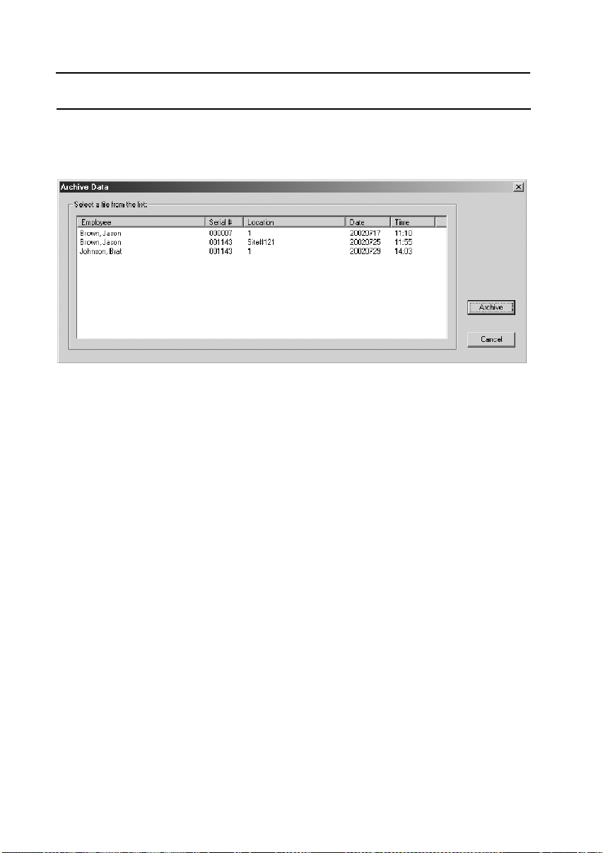
MAN-MAXPRO
REV. B.0.
7. DATA LOGGING
• The file can be opened in most major spreadsheet
programs (such as Microsoft Excel).
Figure 13 A screenshot of the Archive Data dialog box.
7.13 RECOVERING DATA
The Recover Data function enables the transfer of missing
data from a temporary file to the Open dialog for easy access
if a file cannot be accessed after a successful download.
• Click on the Utility menu, then on Recover Data, or simply
click on the Recover Data button on the toolbar of the Main
Screen. The Recover Data dialog box appears (See
Figure 14).
• In this dialog box, enter the last name, first name, and
location, and then click on OK. The file should now appear
in the Open dialog where it may be accessed in the normal
way.
62
Page 63
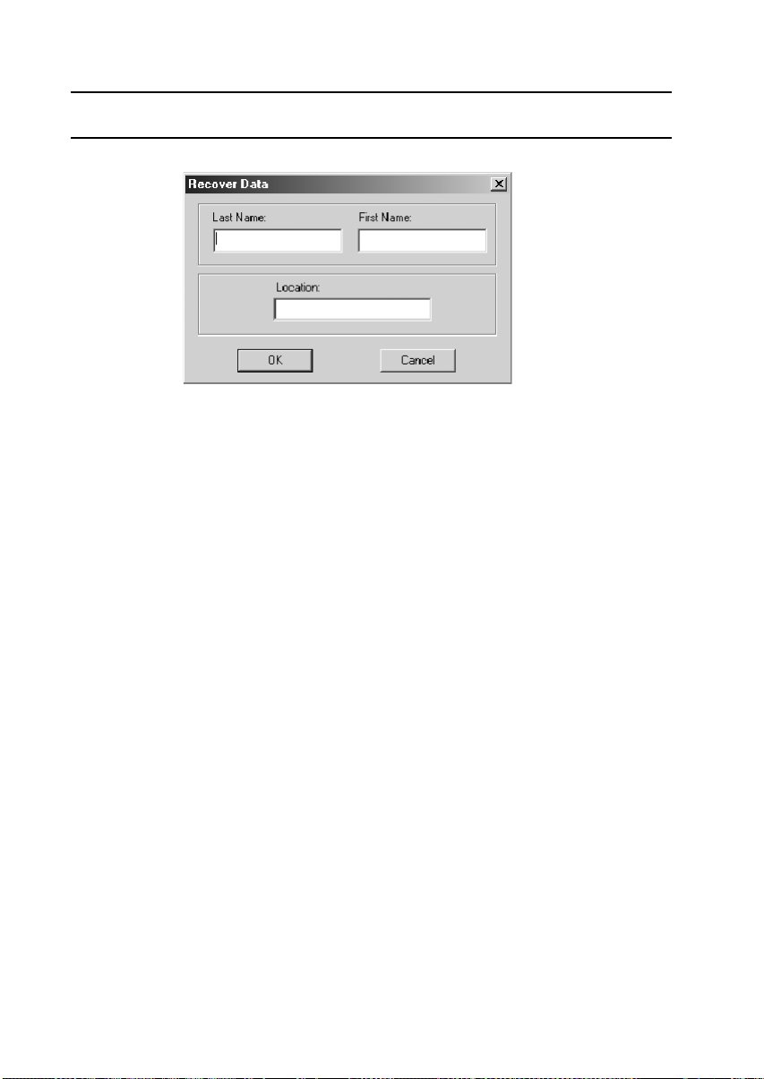
MAN-MAXPRO
REV. B.0.
7. DATA LOGGING
Figure 14 A screenshot of the Recover Data dialog box.
7.14 GETTING HELP
7.14.1 Using MaxPro Log Help
The help function is available from the Main Screen, the Graph
Screen, and the Upload/Modify Instrument Parameters dialog
box.
7.14.2 Lumidor on the Web
User can access different areas of the Lumidor website from
the program. From the Main Screen, click on Help, click on
Lumidor on the Web and then select the area you are
interested in.
7.14.3 Customer Support
From the Main Screen, click on Help and then on Customer
Support. The customer support information is displayed. Click
OK to close it.
7.14.4 MaxPro Log Version and Copyright
From the Main Screen, click on the Help menu and then on
About MaxPro Log. The software version and copyright
information is displayed. Click OK to close it.
63
Page 64

MAN-MAXPRO
REV. B.0.
8. MAINTENANCE
8. MAINTENANCE
8.1 BATTERY INSTALLATION
CAUTION
Use only MPRO NiMH rechargeable battery pack or
MPRO alkaline battery holder with 4 each of the following
alkaline cells only: Duracell Pro-cell-2400, Duracell MN2400 and Eveready E-92 or EN-92. Observe proper
polarity when installing alkaline batteries.
Do not change batteries in a hazardous location.
Open battery compartment by turning the screw (See
Figure 15) a half turn counterclockwise to release.
8.2 ALKALINE BATTERY PACK
INSTALLATION
• Refer to Section 8.1 Battery Installation.
• Remove existing battery pack.
• Insert 4 approved alkaline cells into the supplied alkaline
battery holder. Observe the polarity indicated in the holder
when inserting each cell.
• Insert alkaline battery holder, with 4 approved AAA cells, into
the battery compartment. Observe battery pack contacts
orientation (See Figure 16). This means that the connector
end faces the rear of the instrument where it makes electrical
contact. Once the end with the connector is pushed in, the
rear of the battery pack may be pushed down.
• Push down cover and secure with a half turn clockwise on
screw.
64
Page 65

MAN-MAXPRO
REV. B.0.
8. MAINTENANCE
1/2 turn to release
Figure 15 Battery Compartment
Figure 16 Battery Pack Orientation
8.3 NIMH BATTERY PACK INSTALLATION
•
Refer to Section 8.1 Battery Installation.
• Remove existing battery pack.
• Insert the MPRO NiMH rechargeable battery pack into
battery compartment as shown. (See Figure 16). The
65
Page 66

MAN-MAXPRO
REV. B.0.
8. MAINTENANCE
connector end faces the rear of the instrument where it
makes electrical contact. Once the end with the connector is
pushed in, the rear of the battery pack may now be pushed
down.
• Push down cover and secure with a half turn clockwise on
screw.
• Charge instrument prior to use.
8.4 NIMH BATTERY PACK – GENERAL
INFORMATION
• The supplied NiMH battery pack represents the latest in
battery technology, and as an added benefit, does not have
the environmental problems associated with Nickel
Cadmium technology.
• It should be left on charge when not in use. There is a small
current drain on the pack.
8.5 SENSOR REPLACEMENT
• Turn off the instrument and remove the 4 screws (See
Figure 17) securing the top half of the case.
• Disconnect battery pack connector by lifting it straight up.
• Remove the single screw securing the gas plate (See
Figure 17).
• Remove sensor by lifting it straight up.
• Toxic sensors include a small wafer-thin printed circuit
board as part of the sensor assembly. Make sure that this
board is removed with the sensor.
• If installing a new toxic sensor, it is necessary to remove
any shorting clip or spring attached to the sensor pins.
• Align pins of new sensor with sockets and push down to
secure sensor.
• Reconnect gas plate and secure with screw.
66
Page 67

MAN-MAXPRO
REV. B.0.
8. MAINTENANCE
• Reconnect battery connector.
• Install case cover and secure with 4 case screws.
• Allow sensors to stabilize for 15 minutes prior to turn-on.
• Calibrate the instrument.
8.6 REMOVING AND ADDING A SENSOR
CAUTION
If you are adding or removing a sensor, be aware of the
following:
• Adding a sensor. This involves increasing the number of
sensors in the instrument. For example, to add a fourth
sensor to a three-gas unit, remove the plug, which is
located on the gas plate above the new sensor, so that gas
is allowed to reach the new sensor.
• Removing a sensor. This involves reducing the number of
sensors in the instrument. In this event, it is necessary to
insert a plug (Part number XIF936) in the gas plate to
prevent gas leakage where the vacated sensor no longer
resides.
8.7 CLEANING
Clean exterior of instrument with a clean damp cloth. Do not
use solvents, soap, polishes etc., on the display.
8.8 PUMP INLET FILTER REPLACEMENT
• If the inlet filter is clogged, the flow rate of the pump is
decreased, and in severe cases, the instrument will go into
low flow alarm, or the pump can be heard to be struggling
under the increased load caused by the restriction.
• To replace the filter, use tweezers to pull out the tubing and
filter. Install a new filter (Part number XIP604) and secure
67
Page 68

MAN-MAXPRO
REV. B.0.
8. MAINTENANCE
with 0.05” of tubing (Part number GFV194). The new filter
is held in place by the tubing (Part number GFV194).
8.9 SAMPLING HOSE MAINTENANCE
• Check water trap (Part number GFV196), the spherical disc
located near the middle of the sampling hose, periodically
to make sure it is clean and unobstructed. Replace if
necessary.
• Check the porous dust cap (Part number 20HFC), located
at the very end of the sampling hose, periodically to make
sure it is clean and unobstructed. Replace if necessary.
8.10 STORAGE
If the instrument will be out of service for more than 2 months:
• Charge NiMH battery pack.
• Remove NiMH or alkaline pack from instrument.
• Remove O2 sensor if more than two years old.
• Store the instrument in a contaminant-free area.
• Store the instrument at ambient temperature.
8.11 SENSOR AND BATTERY DISPOSAL
The U.S. Environmental Protection Agency (EPA) governs the
disposal of waste products in the United States. EPA
Regulations are listed in the code of Federal Regulations,
CFR40, entitled “Protection of Environment.” Individual states
and local communities may also establish regulations covering
disposal of waste products. These may be more stringent than
Federal Regulations and may cover disposal of household
waste, which is not included in Federal Regulations. Thus,
state and local agencies should be contacted for their disposal
requirements.
68
Page 69

MAN-MAXPRO
REV. B.0.
8. MAINTENANCE
Battery pack
connector
Gas plate
Figure 17 Sensor Replacement
69
Page 70

MAN-MAXPRO
REV. B.0.
9. TROUBLESHOOTING
9. TROUBLESHOOTING
9.1 SENSOR NOT RECOGNIZED (“XXX”
DISPLAYED)
When “XXX” is shown in sensor position on the display, it
indicates a missing or defective sensor. If it is a LEL sensor,
the sensor may need to be zeroed using the procedure in
Section 9.2 “LEL FAIL” Message.
9.2 “LEL FAIL” MESSAGE
When this message comes up after start-up, you can reset the
zero base of the LEL sensor as follows:
Turn on the instrument.
(1) When the instrument displays “TESTING” and
“PLEASE WAIT” and starts to count down from 30,
depress and hold the MODE button for about 5 seconds,
until display reads “SEL LEL GAS TYPE”.
(2) Open the instrument by removing the 4 screws from the
rear cover of the case. Do not unplug the wires from the
rear cover to the sensor board. Observe the
potentiometer (trimpot) for the LEL zero. It is located
beside the pump and is the only potentiometer (trimpot)
in the instrument.
(3) Set digital voltmeter to the DC voltage range, black lead
to test point 12 (analog ground) and the red lead to test
point 10. These test points are on the same sensor
board as the pump, trimpot and sensors.
(4) Adjust the potentiometer (trimpot) for a reading of 0.500
volts (+/- 0.005 volts).
(5) Reinstall cover.
(6) Exit supervisory mode.
70
Page 71

MAN-MAXPRO
REV. B.0.
9. TROUBLESHOOTING
9.3 LOW FLOW ALARM WHEN SAMPLING
HOSE ATTACHED
Low flow alarm is activated when a sampling hose is
connected.
(1) Clean the stone filter at end of sampling hose.
(2) Make sure that the sampling hose, or water-trap is not
“kinked” or blocked with debris.
(3) Remove sampling hose, clean or replace inlet filter.
9.4 “CALIBRATION FAIL” MESSAGE
Check for proper gas concentration and expiration date.
9.5 INSTRUMENT WILL NOT TURN ON
Charge instrument or install fresh alkaline batteries.
9.6 INSTRUMENT IS IN DIFFUSION MODE
BUT PUMP COMES ON WHEN
CALIBRATING
This is normal instrument behavior. The pump will
automatically turn off when calibration is complete.
71
Page 72

MAN-MAXPRO
REV. B.0.
APPENDIX A - SPECIFICATIONS
APPENDIX A SPECIFICATIONS
(A) Mechanical
(B) Operating Temperature Range
(C) Operating Relative Humidity Range
(D) Power Sources
(E) Battery Life
(F) Alarm Outputs
Dimensions 4.75”L x 3”H x 1.8”D
(120.65mm x 76.2mm x 45.72mm)
Weight < 17.6 ounces (498.96 grams)
-4 degrees F to + 122 degrees F
(-20 degrees C to + 50 degrees C)
Continuous 0-90% (Noncondensing)
Intermittent 0-95% (Noncondensing)
Rechargeable NiMH battery pack or 4 AAA alkaline
batteries
Rechargeable NiMH pack 12 hours minimum
4 AAA alkaline batteries 9 hours
Audible >90db at 1 foot
Visual Large LED bar; Flashing display
characters
72
Page 73

MAN-MAXPRO
REV. B.0.
APPENDIX A - SPECIFICATIONS
(G) Gas Ranges and Resolution
Sensor Instrument
Range
Combustible (LEL) 0-100% LEL 1%LEL
Combustible (% by vol.) * 0-100% CH4 0.1%(0-9.9%), 1%(10-100%)
Oxygen (O2) 0-40% 0.1%
Carbon Monoxide (CO) 0-999PPM 1PPM
Hydrogen Sulfide (H2S) 0-500PPM 1PPM
Sulfur Dioxide (SO2) 0-20PPM 0.1PPM
Phosphine (PH3) 0-20PPM 0.1PPM
Ammonia (NH3) 0-500PPM 1PPM
Chlorine (CL2) 0-20PPM 0.1PPM
Chlorine Dioxide (CLO2) 0-9.9PPM 0.1PPM
Combo-Tox (CO/H2S) 0-500PPM 1PPM
Nitrogen Dioxide (NO2) 0-50PPM 0.1PPM
Hydrogen Cyanide (HCN) 0-50PPM 1PPM
Resolution
* The % by volume sensor is for monitoring methane, natural gas & hydrogen
only
WARNING
If instrument is used in oxygen environments below 10%,
the displayed LEL reading will be lower than actual value.
In this event, use of dilution tube, part number MAX-DT, is
recommended.
(H) Repeatability
+/- 2%
73
Page 74

MAN-MAXPRO
REV. B.0.
APPENDIX A - SPECIFICATIONS
(I) User Programmable High and Low Alarm Set Points
Sensor Increment Low Range/(Default) High Range/(Default)
Oxygen (O2) 0.5% 18.0-20.5% (19.5%) 21.5-25% (23.5%)
Combustible (% LEL) 5% LEL 5-20%LEL (10% LEL) 15-50%LEL (20% LEL)
Combustible (% by vol.) 0.1% 0.3 - 0.8% (0.5%) 0.9 - 2.0% (1.0%)
Carbon Monoxide (CO) 5PPM 10-50PPM (25PPM) 35-400PPM (35PPM)
Hydrogen Sulfide (H2S) 1PPM 5-15PPM (10PPM) 10-25PPM (20PPM)
Sulfur Dioxide (SO2) 0.5PPM 0.5-2.0PPM (1.0PPM) 1.0- 5.0PPM (2.0PPM)
Phosphine (PH3) 0.1PPM 0.2-0.5PPM (0.2PPM) 0.3 to 1.0PPM(0.3PPM)
Ammonia (NH3) 5PPM 5-20PPM (15PPM) 20-50PPM (25PPM)
Chlorine (CL2) 0.1PPM 0.3-1.0PPM (0.3PPM) 0.5-2.0PPM (0.5PPM)
Chlorine Dioxide (CLO2) 0.1PPM 0.2.-0.4PPM (0.3PPM) 0.3-1.0 PPM (0.5PPM)
Combo-Tox (CO/H2S) 5PPM 20-50PPM (25PPM) 25-100PPM (35PPM)
Nitrogen Dioxide (NO2) 0.5PPM 0.5-3.0PPM (3.0PPM) 2.0-5.0PPM (5.0PPM)
Hydrogen Cyanide (HCN) 1PPM 3-5PPM (3PPM) 5-10PPM (5PPM)
(J) Time Weighted Averages (Only if "TWA ON" is
selected) (Toxic sensors only)
Sensor Instantaneous STEL TWA
Carbon Monoxide (CO) 200PPM 100PPM 35PPM
Hydrogen Sulfide (H2S) 20PPM 15PPM 10PPM
Sulfur Dioxide (SO2) 10.0PPM 5.0PPM 2.0PPM
Phosphine (PH3) 5.0PPM 1.0PPM 0.3PPM
Ammonia (NH3) 50PPM 35PPM 25PPM
Chlorine (CL2) 5.0PPM 1.0PPM 0.5PPM
Chlorine Dioxide (CLO2) 1.0PPM 0.3PPM 0.1PPM
Combo/Tox (CO/H2S) 200PPM 100PPM 35PPM
Nitrogen Dioxide (NO2) 5.0PPM 5.0PPM 3.0PPM
Hydrogen Cyanide (HCN) 10PPM 5PPM 5PPM
74
Page 75

MAN-MAXPRO
REV. B.0.
APPENDIX A - SPECIFICATIONS
(K) User Programmable Calibration Gas Levels
Sensor Increment Range Defaults
Combustible (% LEL) 5% LEL 5-60% LEL 50% LEL
Combustible (% by vol.) 0.5% 1.0-3.0% 2.5% CH4
Carbon monoxide (CO) 5PPM 50-300PPM 50PPM
Hydrogen sulfide (H2S) 5PPM 5-25PPM 25PPM
Sulfur dioxide (SO2) 5PPM 5-20PPM 10PPM
Phosphine (PH3) 0.1PPM 1.0-5.0PPM 5.0PPM
Ammonia (NH3) 5PPM 10-50PPM 25PPM
Chlorine (CL2) 1PPM 1-10PPM 10PPM
Chlorine Dioxide (CLO2) 1PPM 1-5PPM 1PPM
Combo-Tox (CO\H2S) 5PPM 50-300PPM CO 50PPM CO
Nitrogen Dioxide (NO2) 1.0PPM 2.0-10.0PPM 10.0PPM
Hydrogen Cyanide (HCN) 1PPM 5-20PPM 10PPM
(L) Voice Messaging
User selectable languages:
• English
• Spanish
• French
• German
(M) Response Time Data
GAS RESPONSE TIME (T90)
Oxygen 10
Combustible (LEL) 20
Carbon Monoxide 08
Hydrogen Sulfide 15
Sulfur Dioxide 05
Phosphine 23
Hydrogen Cyanide 21
Note: Consult factory for response time data for other gases.
75
SECONDS
Page 76

MAN-MAXPRO
REV. B.0.
APPENDIX A - SPECIFICATIONS
(N) Cross Sensitivity Data
Cross Sensitivity Data-Toxic
CARBON MONOXIDE
GAS CONCENTRATION
(PPM)
Hydrogen 1000 140
Methane 10,000 <1
Ethylene 50 154
Carbon Monoxide 100 100
Carbon Dioxide 25,000 <2
Sulfur Dioxide 25 38
Nitric Oxide 100 44
Hydrogen Sulfide 25 0
HYDROGEN SULFIDE
GAS CONCENTRATION
(PPM)
TYPICAL RESPONSE
(PPM)
TYPICAL RESPONSE
(PPM)
Hydrogen 500 15
Methane 10,000 <1
Ethylene 500 15
Carbon Monoxide 100 7
Carbon Dioxide 10,000 <3
Hydrogen Sulfide 25 25
SULFUR DIOXIDE
GAS CONCENTRATION
(PPM)
Carbon Monoxide 300ppm <3ppm
Hydrogen Sulfide 15ppm 5ppm
Nitric Oxide 35ppm 0ppm
Nitrogen Dioxide 5ppm negative 5ppm
Chlorine 1ppm no data
Hydrogen 100ppm n/d
Hydrogen Cyanide 10ppm n/d
Hydrogen Chloride 5ppm n/d
Ethylene 100ppm n/d
TYPICAL RESPONSE
(PPM)
76
Page 77

MAN-MAXPRO
REV. B.0.
APPENDIX A - SPECIFICATIONS
PHOSPHINE
GAS CONCENTRATION TYPICAL RESPONSE
Arsine 150ppb 120ppb
Silane 1000ppb 900ppb
Diborane 300ppb 100ppb
Germane 600ppb 510ppb
Sulphur Dioxide 5ppm 1ppm
Hydrogen 100ppm <0.1ppm
Ethylene 100ppm 1.8ppm
AMMONIA
GAS CONCENTRTION
(PPM)
Hydrogen Sulfide 10 0 (NOTE 1)
Sulfur Dioxide 2 0
Hydrochloric Acid 5 0
Phosphine 300 0
Carbon Monoxide 1000 0
Carbon Dioxide 5000 0
Nitrogen 1,000,000 0
Chlorine 1 0
Hydrogen 10,000 0
Hydrocarbons 10,000 0
Hydrogen Cyanide 10 0
Hydrogen Selenide 0.1 0
Diborane 0.1 0
Arsine 1 0
Germane 1 0
Hydrogen Fluoride 4 0
Alcohols 1000 0
NOTE 1. Short term in minute range
TYPICAL RESPONSE
(PPM)
77
Page 78

MAN-MAXPRO
REV. B.0.
APPENDIX A - SPECIFICATIONS
HYDROGEN CYANIDE
GAS (PPM) CONCENTRATION
(PPM)
Hydrogen Sulfide 10 40
Sulfur Dioxide 2 0 (Note)
Hydrochloric Acid 5 0 (Note)
Phosphine 0.3 0
Carbon Monoxide 1000 0
Carbon Dioxide 5000 0
Nitrogen 1,000,000 0
Chlorine 5 Neg. 1
Hydrogen 1000 0
Nitrogen Dioxide 10 Neg. 12
Hydrocarbons 10,000 0
Nitrogen Monoxide 100 0
Arsine 0.1 0
Hydrogen Fluoride 3 0
Alcohols 1000 0
Ozone 0.1 0.2
Note: Short term exposure minutes.
CHLORINE DIOXIDE
GAS CONCENTRATION
(PPM)
TYPICAL RESPONSE
(PPM)
TYPICAL RESPONSE
(PPM)
Hydrogen sulfide 10 0 (Note)
Sulfur Dioxide 2 0
Hydrochloric Acid 5 0
Phosphine 0.3 0.3
Carbon Monoxide 1000 0
Carbon Dioxide 5000 0
Nitrogen 1,000,000 0
Chlorine 1 0 (Note)
Hydrogen 10,000 0
Hydrocarbons 10,000 0
Hydrogen Cyanide 10 0
Hydrogen Selenide 0.1 0
Arsine 1 0.8
Hydrogen Fluoride 3 0
Alcohols 1000 0
Ozone 0.1 0.03
Note: Short gas exposure in minute range
78
Page 79

MAN-MAXPRO
REV. B.0.
APPENDIX A - SPECIFICATIONS
CHLORINE
GAS CONCENTRATION
(PPM)
Hydrogen Sulfide 10 Neg. 0.3 (Note 1)
Sulfur Dioxide 5 0
Carbon Monoxide 300 0
Carbon Dioxide 10,000 0
Nitrogen 1,000,000 0
Nitrogen Dioxide 10 1.2
Bromine 1 1
Fluorine 1 0.44
Chlorine Dioxide 0.25 0.05
Hydrogen Chloride 20 0
Hydrocarbons 10,000 0
Hydrogen 1000 0
Hydrogen Cyanide 10 0
Ethanol 66,000 0
Ammonia 65 0
Note 1: Continuous exposure will damage cell
NITROGEN DIOXIDE
GAS CONCENTRATION
(PPM)
TYPICAL RESPONSE
(PPM)
TYPICAL RESPONSE
(PPM)
Hydrogen sulfide 10 no data
Sulfur dioxide 50 0
Hydrochloric Acid 5 0
Phosphine 0.1 0
Carbon Monoxide 1000 0
Carbon Dioxide 5000 0
Nitrogen 1,000,000 0
Chlorine 1 3
Hydrogen 1000 0
Hydrocarbons 10,000 0
Ammonia 30 0
Ozone 1 0.7
Diborane 0.1 0
Arsine 0.1 0
Germane 1 0
Fluorine 3 0
Alcohols 1000 0
Nitrogen Monoxide 100 0
79
Page 80

MAN-MAXPRO
REV. B.0.
APPENDIX A - SPECIFICATIONS
COMBO-TOX (CO/H2S)
GAS CONCENTRATION
(PPM)
Hydrogen Sulfide 15 38
Sulfur Dioxide 5 2.5
Nitric Oxide 35 10
Nitrogen Dioxide 5 Neg3
Chlorine 1 <Neg1
Hydrogen 100 <40
RESPONSE (PPM)
LEL Cross Sensitivity Data
CAUTION
The following is not applicable to CH4 % by volume
sensor)
Gas/Vapor Relative Span
Acetone 50
Allyl alcohol 50
Benzene 44
Butane 51
Butan-2-one (MEK) 48
Butyl Acetate 36
Cyclohexane 44
Di n-butyl ether 43
Ethane 82
Ethanol 64
Ethene 81
Ethyl acetate 46
Ethyl benzene 30
Ethylene oxide 64
Hexane 46
Heptane 44
Hydrogen 107
Methane 100
80
Page 81

MAN-MAXPRO
REV. B.0.
APPENDIX A - SPECIFICATIONS
Gas/Vapor Relative Span
Methanol 84
Methylamine 80
Methylethylketone 48
Methyl,t-butylether 44
n-Propanol 50
Octane 38
Pentane 50
Propane 63
Propan-2-ol (IPA) 49
Propylene 64
Propylene Oxide 46
Styrene 32
Tetrahydrofuran 64
Toluene 44
t-Butylalcohol 74
Xylene 31
Note: This section below should be disregarded if you have
chosen the "LEL GAS TYPE" in the supervisory mode).
The cross sensitivity data above contains the relative span for
a number of combustible gases. This information enables the
following cross sensitivity calculations:
(1) Instrument reading in LEL when exposed to a specific
combustible gas included in the table:
Instrument reading in LEL
Example 1: What will an instrument, calibrated to
(2) The actual gas concentration applied to an instrument,
when an LEL reading is observed.
LEL concentation of gas applied relative span of gas applied×
------------------------------------------------------ ----------------------------------------------------------------------------------------------- ---------------=
relative span of calibration gas
methane, read when exposed to 10%
toluene?
Calculation:
10 x 44
--------------------- = 4.4%LEL toluene
100
81
Page 82

MAN-MAXPRO
REV. B.0.
APPENDIX A - SPECIFICATIONS
Gas concentration applied (LEL)
Example 2: An instrument, calibrated to methane,
Calculation:
(O) General
Sample Flow Rate:
The pump in the Micromax Pro samples at 450 cc/minute. Use
of the supplied sampling accessories requires the user to be
aware that delay time will occur based on the length of tubing.
Refer to Section 4.5 Remote Sampling (Pretesting) for details.
If the sample flow is restricted or below pre-determined limits,
the Micromax Pro will indicate a flow failure alarm and for
safety reasons will automatically switch to diffusion mode. In
diffusion mode, the sampling pump does not operate but the
instrument is fully operational and will sense the atmosphere
surrounding the instrument.
Refer to Section 8.8 Pump Inlet Filter Replacement for
maintenance.
Instrument reading (LEL) relative span of calibration gas×
------------------------------------------------------------ ------------------------------------------------------------------------------------ ---------=
relative span of gas applied
reads 22%LEL when exposed to propane.
What is the level of propane being applied?
22 x 100
------------------------- = 34.9%LEL propane
63
DO NOT USE non-standard sampling tube or fittings.
Storage:
Temperature Range: -20 degrees C to + 50 degrees C
(-4 degrees F to + 122 degrees F)
Humidity Range: 0-95% (Noncondensing)
Expected Life: Instrument - 10 Years
Sensors - 2 Years
Batteries - NiMH 2 Years
82
Page 83

MAN-MAXPRO
REV. B.0.
APPENDIX A - SPECIFICATIONS
Oxygen Enriched Atmospheres:
This instrument is safe for use in normal oxygen (20.9%v/v)
atmosphere. In enriched oxygen atmospheres (above 21%)
extreme caution should be exercised as electrical safety
certification is not applicable nor has it been tested as being
safe to use in such atmospheres.
Oxygen Deficient Atmospheres:
The LEL readings cannot be relied upon in atmospheres
deficient of oxygen. For example, most catalytic sensors
cannot be relied upon when oxygen is lower than 10% v/v.
Use extreme caution when the oxygen readings are below
10% v/v and do not enter any confined space when oxygen
alarm is operating and/or reading shows less than 19.5% v/v.
83
Page 84

MAN-MAXPRO
REV. B.0.
APPENDIX B - TURN-ON SEQUENCE
APPENDIX B T URN-ON SEQUENCE
DISPLAY
MICROMAX PRO
VER 5.0
ON
TESTING
PLEASEWAIT
LED SPEAKER
1
FLASH
“MICROMAX-PRO ON”
“TESTING PLEASE WAIT”
BEEP
BEEP
IF ”AUTO ZERO” IS ON
(DEFAULT=ON)
ZEROING
PLEASEWAIT
BEEP
“ZEROING PLEASE WAIT”
84
Page 85

MAN-MAXPRO
REV. B.0.
ONLY IF SELECTED
(DEFAULT=OFF)
ONLY IF SELECTED
(DEFAULT=OFF)
APPENDIX B - TURN-ON SEQUENCE
LED SPEAKER
LAST CALIBRATED
03/28/2000
CALIBRATION DUE
04/28/2000
BEEP
BEEP
DEFAULT VALUES
SHOWN
DEFAULT VALUES
SHOWN
OX LEL C0 H2S
19.5 10 25 10
LOW ALARM
OX LEL C0 H2S
23.5 20 35 20
HIGHALARM
BEEP
BEEP
85
Page 86

MAN-MAXPRO
REV. B.0.
APPENDIX B - TURN-ON SEQUENCE
LED SPEAKER
NORMAL OPERATING
MODE
Note: Max time from “Turn On” to “Ready” does not exceed
80 seconds.
VOICEON
READY
OX LEL C0 H2S
20.9 0 0 0
P11:52 B
3
FLASHES
1 BEEP”
3 BEEPS,
“MICROMAX PRO
READY””
86
Page 87

MAN-MAXPRO
REV. B.0.
APPENDIX C - MODE SEQUENCE, STANDARD MODE
APPENDIX C MODE SEQUENCE, STANDARD MODE
LED SPEAKER
OX LEL C0 H2S
ON
OFF
ON
OFF
TO CLEAR
TO CLEAR
PEAK VALUES
PEAK VALUES
TO ENTER
USER SETUP
20.1 0 16 9
PEAKREADING
OX LEL CO H2S
20.9 0 0 0
PEAKCLEARED
OX LEL C0 H2S
42
STELREADING
OX LEL C0 H2S
20.3 6 8 3
AVG READING
LEL C0 H2S
USERSETUP
NO
BEEP,
“PEAK READINGS”
3 BEEPS,
“CLEARED”
BEEP,
“STEL READINGS”
BEEP,
“AVERAGE READINGS”
BEEP
OX LEL C0 H2S
20.9 0 0 0
P08:49 B
BEEP
Note: Use the MODE button to scroll through these screens.
87
Page 88

MAN-MAXPRO
n
REV. B.0.
APPENDIX D - MODE SEQUENCE, USER SET-UP MODE
APPENDIX D MODE SEQUENCE, USER SET-UP MODE
Note: See Appendix C Mode Sequence, Standard Mode for how to
enter User Set-up Mode.
LED SPEAKER
DEFAULT=ON
DEFAULT=ON
DEFAULT=OFF
PUMPSTATUS
ON
VOICE STATUS
ON
CONFIDENCE
ON
BEEP
“PUMP ON”
OR
“PUMP OFF”
BEEP
“VOICE ON”
BEEP
“CONFIDENCE OFF”
OR
“CONFIDENCE ON”
A
Notes: 1. There will be no voice message if “VOICE” is turned off i
User Set-Up Mode.
2. Use the MODE button to scroll through these screens.
88
Page 89

MAN-MAXPRO
REV. B.0.
APPENDIX D - MODE SEQUENCE, USER SET-UP MODE
Calibration
ON
OFF
MODE
TO ENTER
CAL MODE
TO ZERO AND
EXIT, WITHOUT
CALIBRATING,
HOLD 3 SEC
ANYTIME
DURING
COUNTDOWN
A
OX LEL C0 H2S
20.9 0 0 0
CALIBRATE?
OX LEL C0 H2S
ZEROING
PLEASE WAIT
OX LEL C0 H2S
APPLY GAS
B
LED SPEAKER
BEEP
“CALIBRATION MODE
ON”
3 BEEPS,
“ZEROING COMPLETE”
“APPLY GAS”
89
Page 90
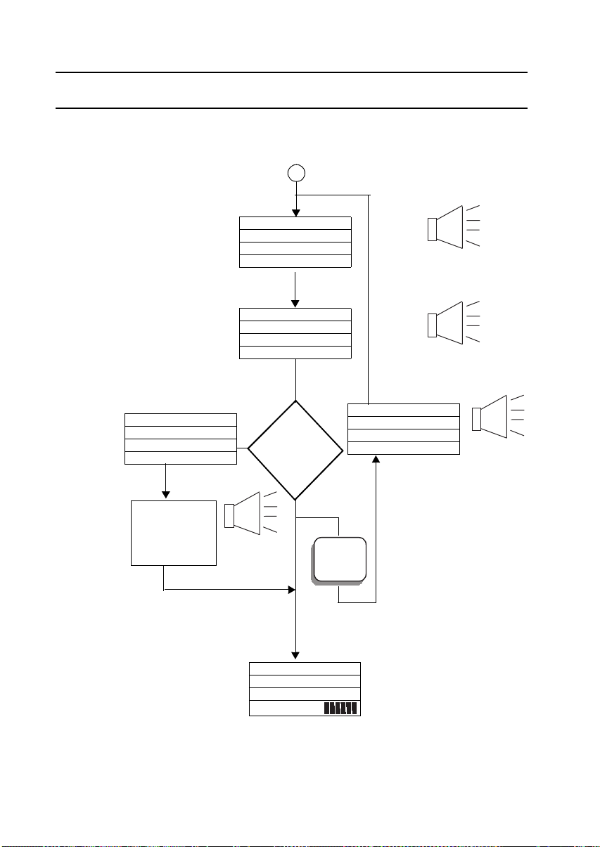
MAN-MAXPRO
REV. B.0.
APPENDIX D - MODE SEQUENCE, USER SET-UP MODE
Calibration
“CALIBRATION
COMPLETE” (ONLY
SHOWS GASES
CALIBRATED)
OX LEL C0 H2S
20.9 5 5 25
PURGING
PLEASEWAIT
AUTOMATIC
MEMORY
CLEAR AFTER
PURGING
OX LEL C0 H2S
CALIBRATING
PLEASEWAIT
OX LEL C0 H2S
CAL COMPLETE
OX LEL C0 H2S
GASES CAL
CORRECTLY?
YES
3 BEEPS
“CLEARED”
B
ALL
LED SPEAKER
BEEP
“CALIBRATING”
3 BEEPS
“CALIBRATION COMPLETE”
OX LEL C0 H2S
APPLY GAS
“APPLY
GAS”
NO
ON
OFF
NORMAL
OPERATING
MODE
OX LEL C0 H2S
20.9 0 0 0
P10:56 B
90
Page 91

MAN-MAXPRO
REV. B.0.
APPENDIX D - MODE SEQUENCE, USER SET-UP MODE
Calibration Failure
LED SPEAKER
OX LEL C0 H2S
APPLYGAS
TIME
OUT
OX LEL C0 H2S
APPLYGAS
CAL FAILURE
OX LEL C0 H2S
20.9 0 0 0
P 08:49 B
3 BEEPS,
“CALIBRATION FAIL”
91
Page 92
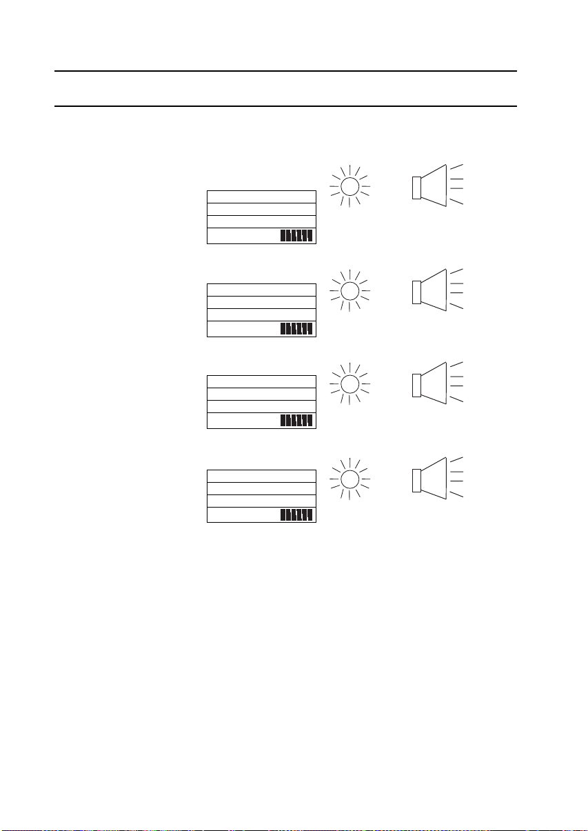
MAN-MAXPRO
REV. B.0.
APPENDIX E AL ARM MODES
APPENDIX E - ALARM MODES
LED SPEAKER
LOW GAS
ALARM
(VOICE: DANGER
FOR O2 ONLY)
HIGH GAS
ALARM
LOW FLOW
ALARM
OX LEL C0 H2S
20.9 0 0 0
WARNING
P 08:49 B
OX LEL C0 H2S
20.9 0 0 0
DANGER
P 08:49 B
OX LEL C0 H2S
20.9 0 0 0
LOW FLOW
P 08:49 B
OX LEL C0 H2S
20.9 0 0 0
PUMPFAIL
P 08:49 B
FLASH 3 BEEPS
“WARNING” OR
“DANGER” FOR O2
FLASH 3 BEEPS
“DANGER”
FLASH CONTINUOUS
HORN
FLASH LONG CONTINUOUS
BEEPS
92
Page 93
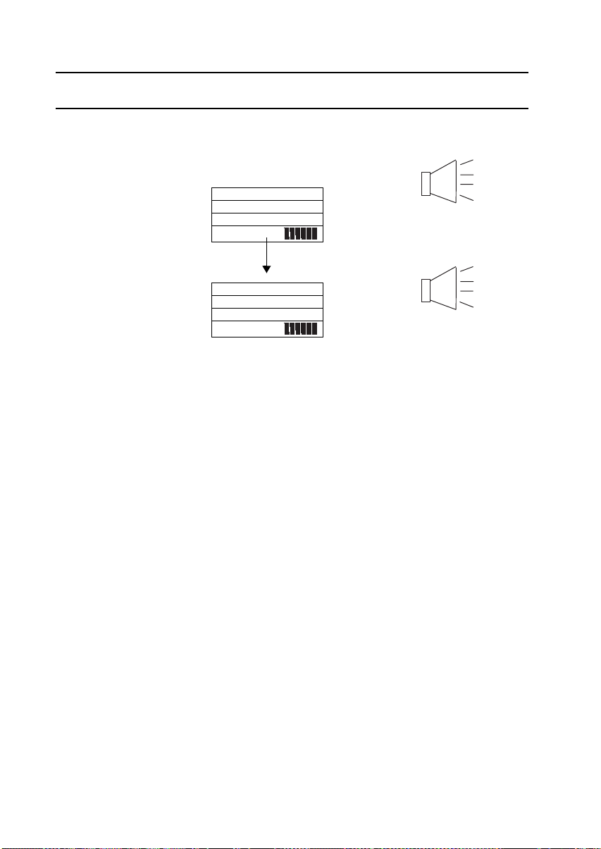
MAN-MAXPRO
REV. B.0.
APPENDIX E - ALARM MODES
LED SPEAKER
LOW BATTERY
WARNING
BATTERY
DEPLETED
OX LEL C0 H2S
20.9 0 0 0
LOW BATTERY
P08:49 B
OX LEL C0 H2S
20.9 0 0 0
BATT. DEPLETED
P08:49 B
2 SHORT BEEPS, 15 TO
20 SEC.
5 BEEPS
TURN OFF
93
Page 94

MAN-MAXPRO
REV. B.0.
APPENDIX F - CHARGING SCREENS
APPENDIX F CHARGING SCREENS
“BLANK”
(1) When unit is turned off.
(2) When an attempt is made to
“CHARGING”
(1) When charger is connected and
“CHARGE COMPLETE”
(1) Remains on screen until
“CHECK BATTERY”
(1) When unit is placed on charge
(2) When unit is placed on charge
turn on but battery is very low.
charging.
charger is removed.
with alkaline battery.
with a defective battery, or if
battery is defective.
CHARGINGBATTERY
CHARGECOMPLETE
CHECKBATTERY
(3) When unit is placed on charge
without battery.
94
Page 95

MAN-MAXPRO
REV. B.0.
APPENDIX G - CALIBRATION KITS
APPENDIX G CALIBRATION KITS
Model No. Description
MPRO-KIT # 1 Kit containing 58-liter calibration gas
MPRO-KIT # 1 - MINI Kit containing 34-liter calibration gas
MPRO-KIT # 2 Kit containing 103-liter calibration gas
MPRO-KIT # 5 Alarm test kit containing "bump check"
MPRO-KIT # 7 Kit containing 23-liter minimix
MPRO-KIT #10 -MINI Kit containing 34-liter calibration gas
TEST-1A Alarm check gas - single canister.
TEST-1A-6 Alarm check gas - six pack.
TEST-1A-12 Alarm check gas - twelve pack.
cylinder (GFV207-CH4, CO, H2S,
balance air), regulator with gauge,
tubing, and high impact waterproof
carrying case (MCC215A).
cylinder (GFV243-CH4, CO, H2S,
balance air), regulator, tubing, and
water resistant carrying case
(MCC210A).
cylinder (GFV123-CH4, CO, balance
air), regulator with gauge, tubing, and
high impact waterproof carrying case
(MCC215A).
gas cylinder (TEST-1A), and water
resistant carrying case (MCC210A).
calibration gas in steel cylinder
(GFV1090-CH4, CO, balance air),
regulator, tubing, and water resistant
carrying case (MCC210A).
cylinder (GFV279-CH4, CO, SO2,
balance air), regulator, tubing, and
water resistant carrying case
(MCC210A).
95
Page 96

MAN-MAXPRO
REV. B.0.
APPENDIX H - OPTIONAL ACCESSORIES
APPENDIX H OPTIONAL ACCESSORIES
Model No. Description
MPRO-EAR Earphone assembly
MPRO-VIB Vibrator assembly
MPRO-15 Adapter for charging a single battery
MPRO-2 230V 50Hz AC charger
MPRO-6 Vehicle charger
MAX-18 Collapsible fiberglass search probe (30")
MAX-19 Collapsible aluminum search probe (30")
16-21 Filter (4") with water-trap and dust filter
16HEX-10 Hose extension (10') with fittings
16HEX-20 Hose extension (20') with fittings
MAX-DT Dilution tube
MCC215A Waterproof briefcase style case (Houses
monitor and calibration kit)
96
Page 97

MAN-MAXPRO
REV. B.0.
APPENDIX I - REPLACEMENT PARTS
APPENDIX I REPLACEMENT PARTS
PART NUMBER DESCRIPTION
MPRO-BPR NiMH rechargeable battery pack
MPRO-1 120V AC 4hr charger for MPRO-BPR
MPRO-BPA Alkaline battery holder
MCF-930 Rubber boot
16-27 Sampling hose (10’) with water and dust
16-27T Sampling hose (10') with water and dust
16-PFC Dust filter (2.5”)
GFV107 PVC hose tubing (sold by the foot)
GFV256 Tygon hose tubing (sold by the foot)
GFV196 Replacement water filter
20HFC Replacement dust filter
MPRO-DATALOG Data logging software and cable
MPRO-LOG Data logging software (CD ROM)
MPRO-COMM Data logging communications cable
MPRO-02 O2 sensor with ID board
MPRO-CL Chlorine sensor with ID board
MPRO-CLO Chlorine Dioxide sensor with ID board
MPRO-NO2 Nitrogen Dioxide sensor with ID board
MPRO-TCS-E % by volume (CH4) sensor
MPRO-ES-S LEL sensor
MAX-CS-S Carbon Monoxide sensor with ID board
MAX-HS-S Hydrogen Sulfide sensor with ID board
MAX-SS Sulfur Dioxide sensor with ID board
MAX-NH Ammonia sensor with ID board
MAX-PS Phosphine sensor with ID board
MAX-HCN-K Hydrogen Cyanide sensor with ID board
filters
filters With Tygon tubing (for use with SO2,
CLO2, CL, PH3, NH3, and NO2)
97
Page 98

MAN-MAXPRO
REV. B.0.
APPENDIX I - REPLACEMENT PARTS
MAX-TOX CO/H2S COMBO-TOX sensor w/ID board
MPRO-SB Sensor board assembly
MPRO-DB Digital board assembly
MPRO-VB Voice board assembly
MPRO-GSP Pump assembly
MPRO-MC Main case assembly
HSR476 Case screw (4 required)
XIF936 Gas-plate hole plug
MAX-IF Inlet fitting with “O” ring, screen and plastic
fitting
HOR 123 “O” Ring (for inlet)
XIP604 Filter screen (for inlet)
GFV194 Plastic fitting (for inlet)
98
Page 99

MAN-MAXPRO
REV. B.0.
APPENDIX J - CALIBRATING WITH MULTIPLE CANISTERS
APPENDIX J CA LIBRATING WITH MULTIPLE CANISTERS
Whether the calibration procedure falls under Section 5.2
Calibration Procedure (when all calibration gases are in a
single canister) or under Section 5.3 Calibration Procedure
(when not all calibration gases are in a single canister) is
dependent on the instrument's sensor complement. If the
sensor complement is O2, LEL, CO and H2S, all four
calibration gases are available in one canister (GFV207 or
GFV243). Similarly, if the sensor complement is O2, LEL, CO
and SO2, all four calibration gases are available in one
canister (GFV279). Again, if the sensor complement is O2,
LEL, and CO then all three-calibration gases are available in
one canister (GFV123). GFV123 would also be used where
the sensor complement is O2 and LEL.
Where not all the calibration gases are available in a single
canister, the position is as follows:
(1) Five-gas models with combo-tox sensor
First, apply GFV123 (O2, LEL and CO). Then apply the
gas appropriate to the other toxic sensor in the unit. Do
not calibrate the combo-tox sensor with H2S gas.
Four-gas models with O2, LEL and CO sensors
First, apply GFV123 (O2, LEL and CO), followed by the
gas appropriate to the other toxic sensor.
(2) Models with O2 and/or LEL sensors
First, apply GFV123 (O2, LEL and CO), followed by the
gas(es) appropriate to the other toxic sensor(s).
(3) Examples
a. MPRO-4ABCE (O2, LEL, CO and NH3). Follow the
procedure in Section 5.3 Calibration Procedure
(when not all calibration gases are in a single
canister). The first calibration gas is GFV123; the
second calibration gas is either GFV 213 (58 Liters)
or GFV 250 (34 Liters).
99
Page 100

MAN-MAXPRO
REV. B.0.
APPENDIX J - CALIBRATING WITH MULTIPLE CANISTERS
b. MPRO-4ABCH (O2, LEL, CO and SO2). Follow the
procedure in Section 5.2 Calibration Procedure (when all
calibration gases are in a single canister) because all the
calibration gases are in one canister (GFV279).
c. MPRO-2AC(O2&CO).Followtheprocedurein
Section 5.2 Calibration Procedure (when all calibration
gases are in a single canister) because all the calibration
gases are in a single canister (GFV123).
d. MPRO-2EF (NH3 and CL2). Follow the procedure in
Section 5.3 Calibration Procedure (when not all
calibration gases are in a single canister). The first gas is
NH3 (GFV213 or GFV250) and the second gas is CL2
(GFV252 or GFV249).
e. MPRO-AN (O2 and LEL/%by volume). Follow the
procedure in Section 5.2 Calibration Procedure (when all
calibration gases are in a single canister) because all the
gases are in a single cylinder (GFV123).
f. MPRO-4ABCJ (O2, LEL, CO and PH3). Follow the
procedure in Section 5.3 Calibration Procedure (when
not all calibration gases are in a single canister).Thefirst
calibration gas is GFV123; the second calibration gas is
GFV272 (5PPM PH3).
100
 Loading...