How it Works
Log In / Sign Up
Buy Points
How it Works
FAQ
Contact Us
Questions and Suggestions
Users
Honeywell
Loading...
L
L8148A
2
L8148E
2
L8148J
2
L8151A
L91B
2
L91D
2
L91F
LA
LANSRLU1
LCBS
LCBS Connect
2
LCP300-L
4
LCP300-LC
5
LCP500-L
2
LCP500-LC
2
LCT500
LED150
LED170
LED310
LEGIC-Leser
Le Sucre
LF20
LF20-C
LF24
LF507
LG
LGK
Limitless WDRR
Limitless WGLA
Limitless WMPR
LineVoltPRO 7000
LineVoltPRO 8000
2
LION
LKP500-EN
LKP500-ENC
LKPES8M-EN
LKS 131
LKS 160
LKS 310
LLE102000
LLE105000
LonWorks protocol
LP-1200
3
LP907
LP907A
LP914
LP914A
LP915
LP915A
LP916
2
LP916A
4
LP916A-C
LP916B
3
LP916C
3
LP920
LR-HWLV-HVAC
lRTH6350
LTE-CFA
LTE-CFV
LTE-IA
2
LTE-IC
2
LTE-IV
2
LTE-L57C
LTE-L57V
LTE-X
LTE-XA
2
LTE-XC
2
LTE-XV
2
Lumidor Enforcer
Lumidor Impact
3
Lumidor MicroMax Pro
2
Lumidor Minimax X4
2
Lumidor Minimax XP
2
Lumidor Minimax XT
2
Lumidor Safelink
LXE4830P
15
LXE4831P
4
LXE6526M
LXE6726M
LXE6726P
LXE6730M
2
LXEATH
LXEBLUE
LXEBT001
4
LXE-FX1
LXEMX7P1
LXE MX8
LXEMX9GSM2G
LXERFID1
2
LXERFID2
LXERFID3
2
LXE-VM1
2
LXL-1000
LXL-1010
LYNX
Lynx Plus
5
LYNX Touch
11
Lynx Touch 5100
LYNX Touch SIA
LynX Voice Security System
Loading...
Loading...
Nothing found
LP916A
Data Sheet
2 pgs
145.42 Kb
0
Installation Instructions
16 pgs
590.54 Kb
0
Installation Instructions Manual
8 pgs
167.19 Kb
0
User Manual
3 pgs
405.57 Kb
0
Table of contents
Loading...
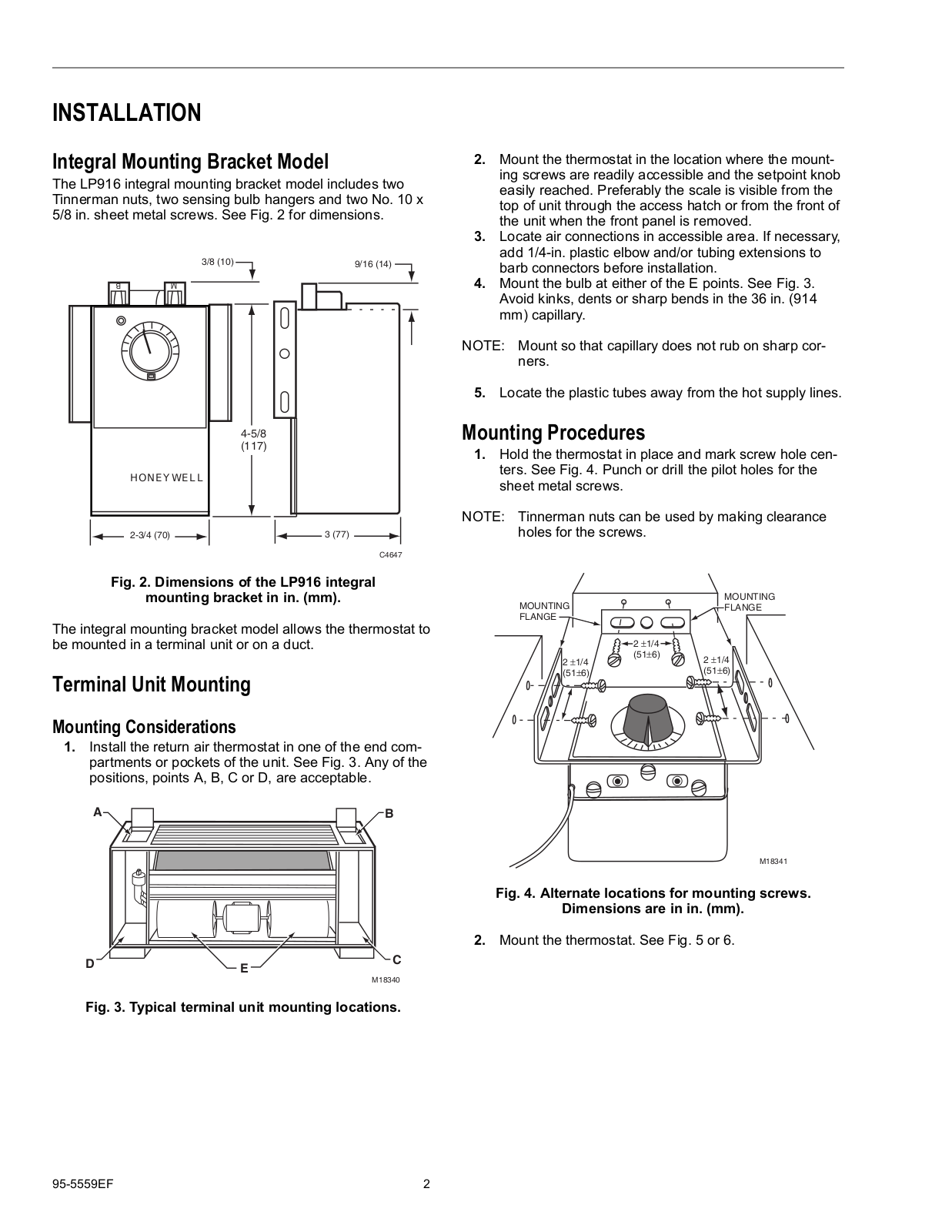
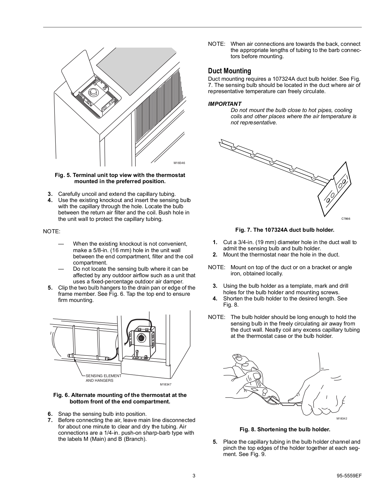
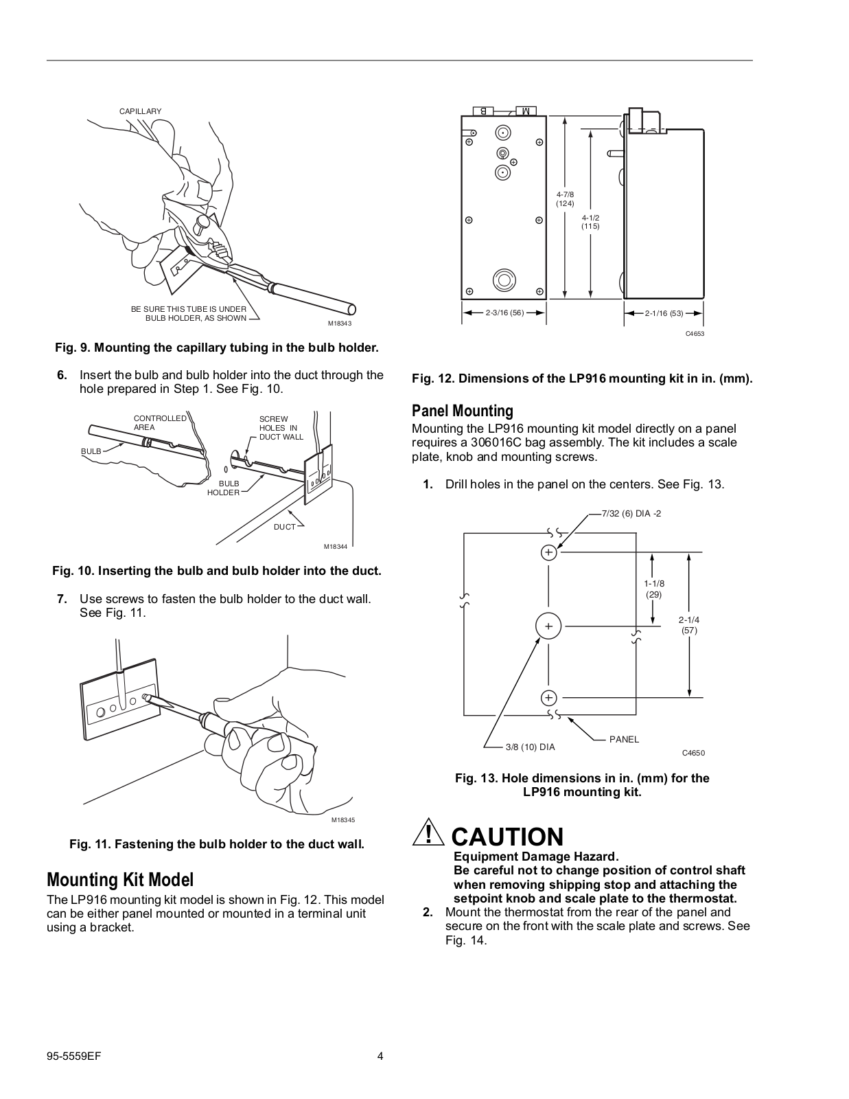
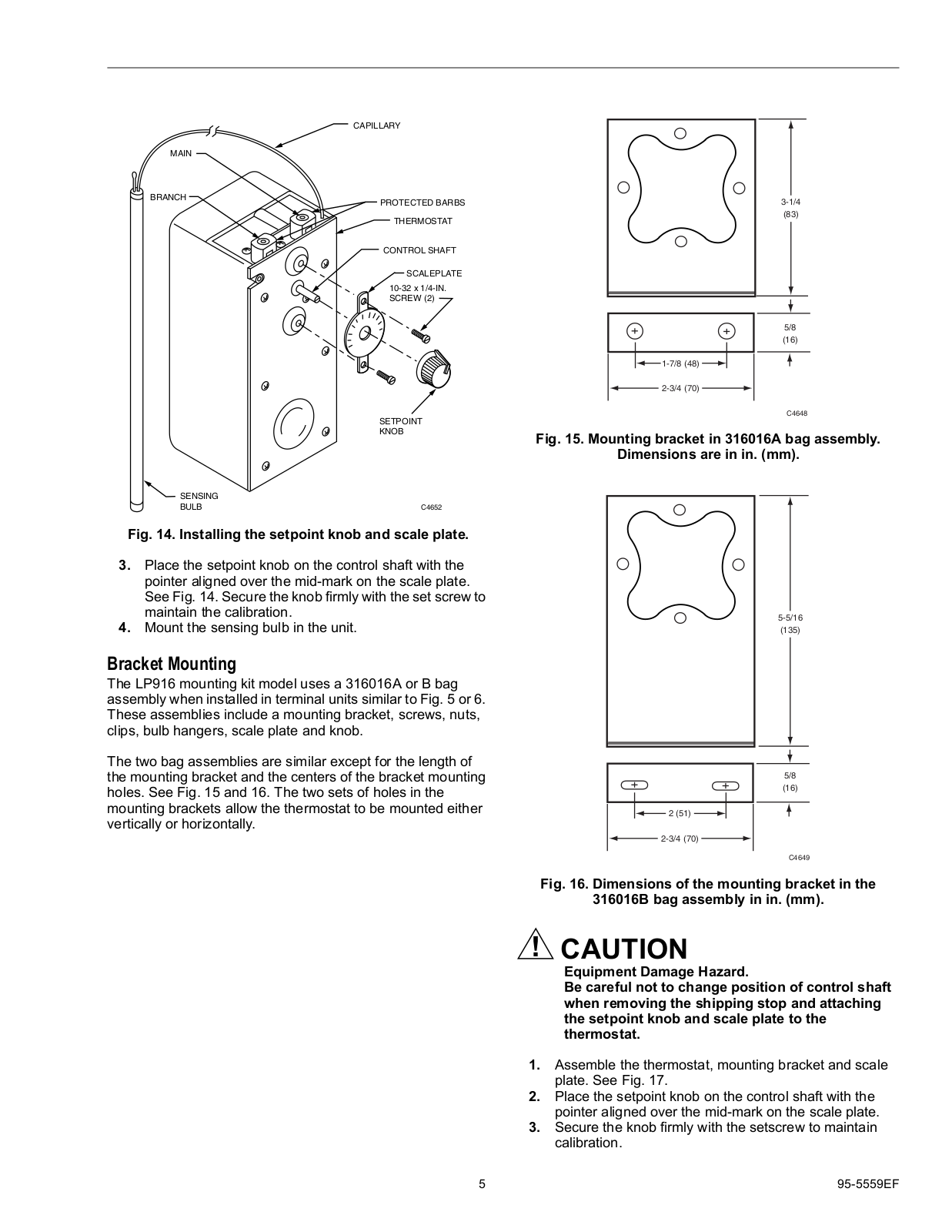
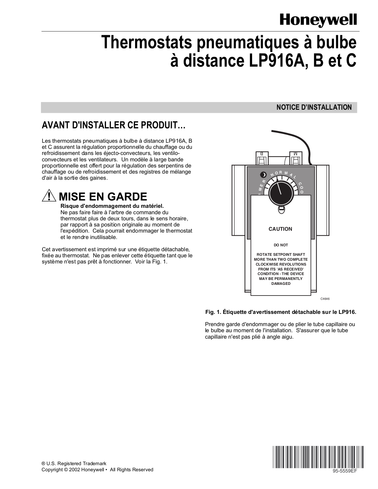
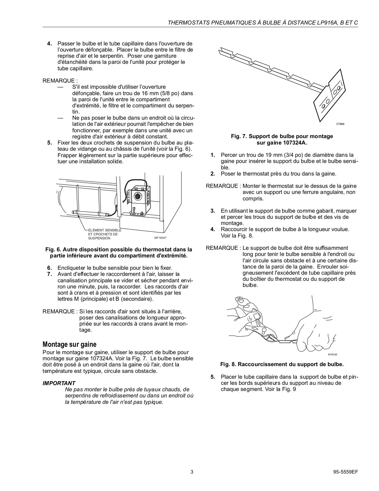
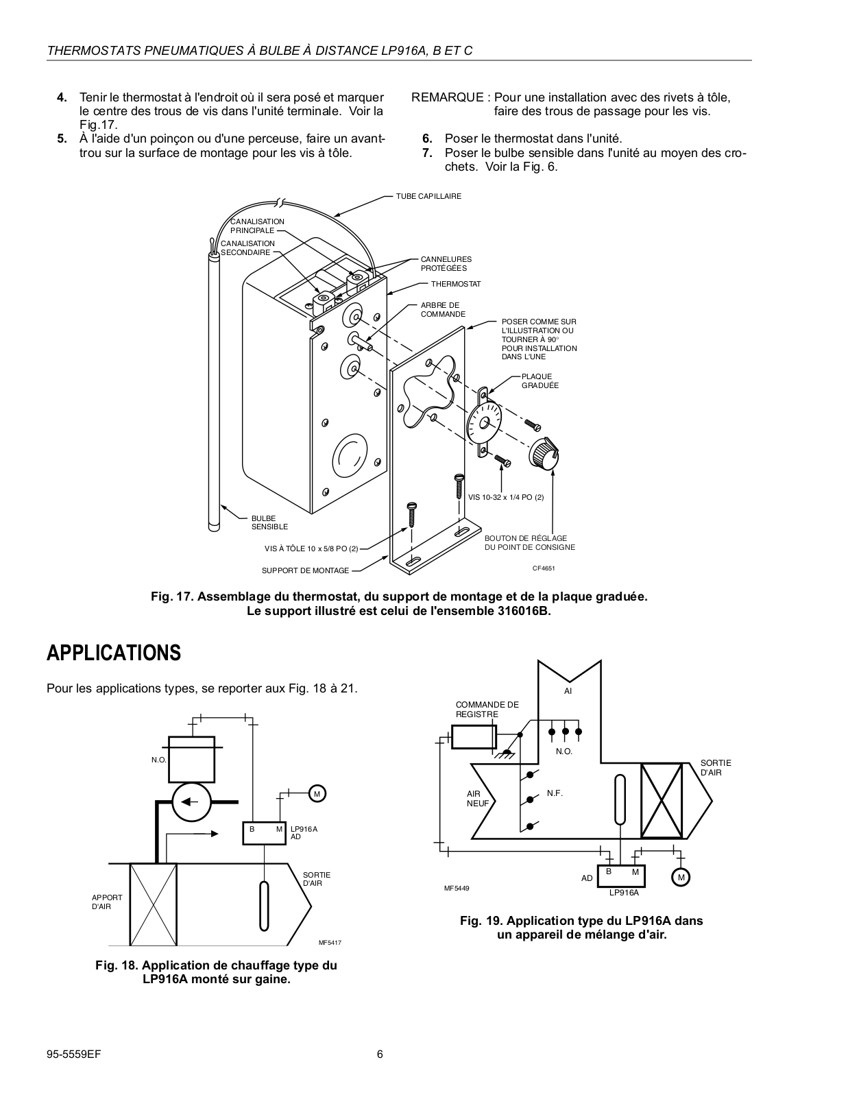
Honeywell LP916A, LP916B, LP916C Installation Instructions
...
Honeywell Installation Instructions
Download
Specifications and Main Features
Frequently Asked Questions
User Manual
Download
Loading...
+
hidden pages
Unhide
You need points to download manuals.
1 point = 1 manual.
You can buy points or you can get point for every manual you upload.
Buy points
Upload your manuals